|
Hasegawa 1/48 scale conversion
Post-Kahu
A-4K Skyhawk
|
 |
|
A-4K Skyahwk
Royal New Zealand Air Force |
by
Anthony Papadis

Hobbycraft's 1/48 scale A-4E Skyhawk is
available online from Squadron.com
The A-4 Skyhawk is an aircraft that almost needs
no introduction.
Designed by ‘Ed’ Heinemann, the aircraft was
affectionately referred to as ‘Heinemann’s Hotrod’
and the ‘Bantam Bomber’ due to its spritely
performance and diminutive size. The aircraft has
seen conflict in several theatres, including
Vietnam, The Middle East and the Falkland Islands,
and has served the in numerous armed forced across
the globe.
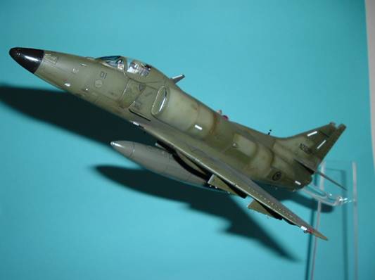
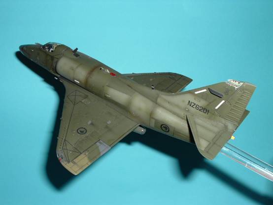
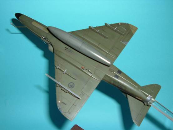
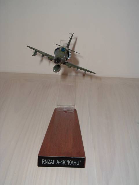
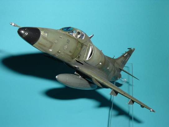
My model depicts a Royal New Zealand Air Force
(RNZAF) A-4K “Kahu”, and is painted in the overall
green, the final scheme these aircraft wore before
they were retired. The aircraft depicted is NZ6201,
which was involved in a potentially fatal incident.
On the 20th March 2001, this aircraft struck a
110,000Volt power line whilst on a low –level
navigation exercise. The collision almost tore the
fin tip completely off.
Fortunately, the pilot was able to safely recover
the aircraft to RNZAF Base Woodbourne, which was
nearby. The fin tip was still hanging by a few
threads on the starboard side!
This kit is the
Hobbycraft 1/48 A-4E/F “Aggressor”. The Hasegawa kit
surpasses the Hobbycraft kit in both detail and ease
of conversion to A-4K, however I have used this kit
as it was bought for a very modest sum thanks to a
swap and sell at the local model club.
Whilst the Hasegawa A-4E/F kit contains just about
everything you need to build a “Kahu”, the
Hobbycraft kit has several deficiencies which I will
outline below. Although the list may seem extensive,
the majority of the items listed were fashioned from
common modelling items and each took no longer than
a few minutes to add or correct.
My changes/additions included:
-
Improving the
rear cockpit shelf behind the seat
-
Adding a pilot,
whose head was re-positioned and oxy hose added
-
Hud glass
-
Adding the VOR
antennas to the fin
-
Adding the rear
ECM antennas
-
Adding the strobe
light to the upper fuselage
-
Replacing all
blade aerials with plastic card
-
Re-positioning
the Nav beacon from the lower left undercarriage
fairing to the right fairing
-
Adding the
wingtip ECM antennas
-
Adding the
underside wingtip lights
-
Adding the
wingtip navigation lights
-
Detailing the
brake parachute opening mechanism
-
Adding the pylon
sway braces
The kit instructions are brief, which posed no
problems. Construction is both straight-forward and
brief.
Starting with the cockpit, a few additional details
were added. The “Kahu” was upgraded substantially in
comparison to the original A-4E. They were fitted
with an APG-66 radar, which is what is fitted to the
F-16. The instrument panel also differs greatly in
that it has two Cathode Ray Tubes (CRT’s) ‘TV’
screens. I decided that since this was to be a
canopy down kit in a flying pose, the extra effort
involved in making the new panel would be wasted as
it would not be seen. This would also be true of the
area behind the seat as it turns out as the canopy
framing obscures this area as well!
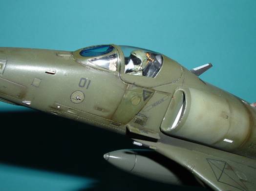
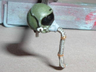
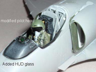 This
picture shows the pilot installed in the
‘office’ with the head moved to the left and
a scratchbuilt oxygen hose added complete
with the microphone lead. I have also added
a small HUD glass from some clear acetate. This
picture shows the pilot installed in the
‘office’ with the head moved to the left and
a scratchbuilt oxygen hose added complete
with the microphone lead. I have also added
a small HUD glass from some clear acetate. |
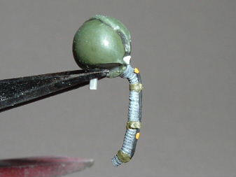
 Here
is a picture of the added oxy hose. I
wrapped 8 Amp fuse wire around 16 Amp fuse
wire and added the mike lead from stretched
sprue. The rings were made from some wine
bottle foil. Here
is a picture of the added oxy hose. I
wrapped 8 Amp fuse wire around 16 Amp fuse
wire and added the mike lead from stretched
sprue. The rings were made from some wine
bottle foil. |
 Another
view, after painting. The oxy hose was
painted dark grey and then dry brushed with
a lighter shade. The mike lead was then
picked out as were the green velcro bands Another
view, after painting. The oxy hose was
painted dark grey and then dry brushed with
a lighter shade. The mike lead was then
picked out as were the green velcro bands |
|
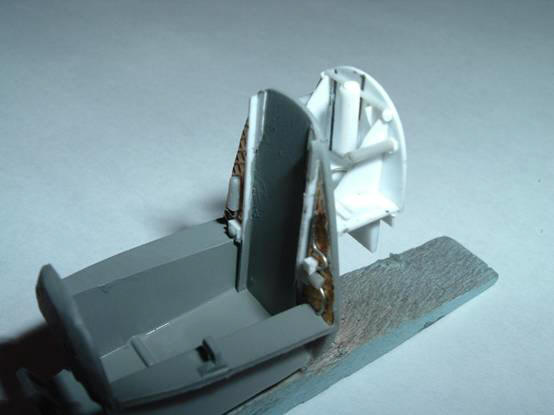
The original kit tub to which was added a
basic throttle quadrant and a scratchbuilt
canopy actuator bay. The rear cockpit
bulkhead had the noise absorbent quilting
added using some ‘sparkling white wine’ foil
and bits of plastic strip and fuse wire.
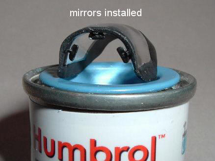
 I
also added a small map to the instrument
coaming as well as the seat ejection handle.
The canopy interior had some rear view
mirrors installed after it was polished and
dipped in Future. I
also added a small map to the instrument
coaming as well as the seat ejection handle.
The canopy interior had some rear view
mirrors installed after it was polished and
dipped in Future. |
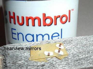
 I
also added a small map to the instrument
coaming as well as the seat ejection handle.
The canopy interior had some rear view
mirrors installed after it was polished and
dipped in Future. I
also added a small map to the instrument
coaming as well as the seat ejection handle.
The canopy interior had some rear view
mirrors installed after it was polished and
dipped in Future.
The mirrors were made from 10 thou
plastic sheet to which a strip of thin
copper was added to provide an attachment
point.
Once the canopy was completed, it was
attached to the cockpit and attention was
then focussed onto the lower fuselage. |
|
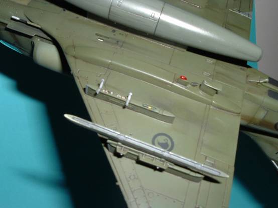
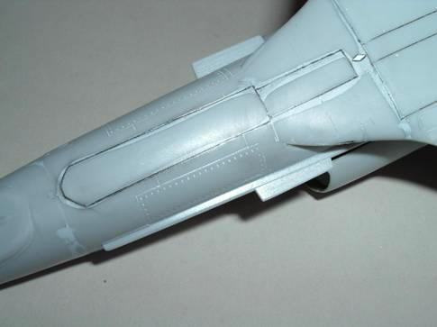
The RNZAF A-4K’s had the lower navigation
beacon situated on the rear of the right
main gear nacelle. This is contrary to most
operators. The beacon was carefully shaved
off the left undercarriage fairing and
transplanted to the right.
|
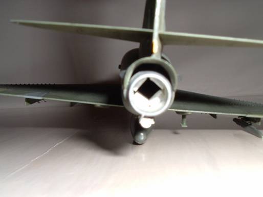
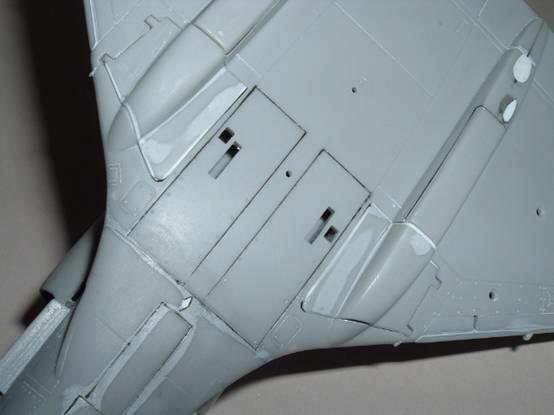
I intended to have the kit mounted in
flight, moments after striking the power
line. This would require the undercarriage
doors to be closed. The kit’s undercarriage
doors fit poorly and I had to use plastic
strips along their edges to fill some of the
gaps.
The nose gear door did not match the
rounded fuselage contour and required some
putty to blend the shape in.
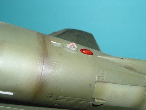
Note the diamond shaped panel. This is
the base for a small antenna found on late
model A-4K’s. |
|
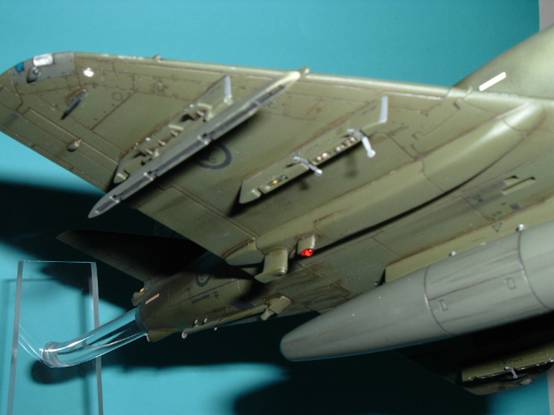
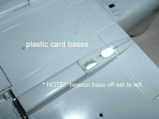
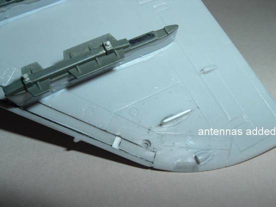
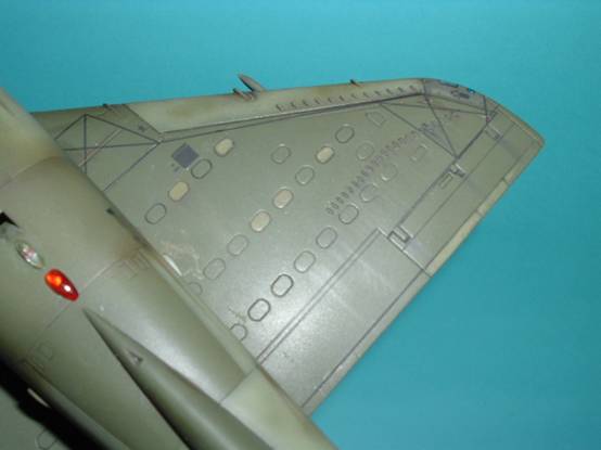
At this point the wings came in for some
attention.
There is a small ECM antenna at each
wingtip. Also missing are the clear round
lights. I also wanted to add a little detail
to the antenna housing under the left wing
tip. There is also an aerial missing from
the right wing. I made a simple plastic card
base and antenna from some 10 thou sheet.
The slats were fitted in the retracted
position and fit with minimal use of putty.
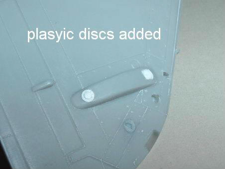 The
round discs were made from some 10 thou
plastic sheet and punched out with a punch
and die set. The
round discs were made from some 10 thou
plastic sheet and punched out with a punch
and die set. |
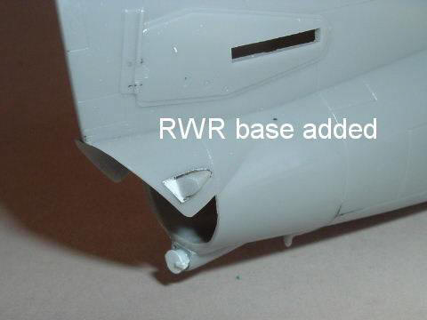
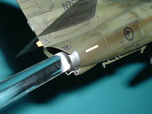
The next area to receive attention was
the rear fuselage. There are two ECM bumps
missing (one per side), just forward of the
exhaust. After making a base from plastic
card, the bumps were made from some suitably
shaped sprue pieces. |
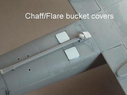 I
also added the chaff/flare bucket covers and
some drainage pipes from bits of plastic
card and sprue. I
also added the chaff/flare bucket covers and
some drainage pipes from bits of plastic
card and sprue.
The covers are in place and the drainage
pipes have yet to be added to their drilled
holes. |
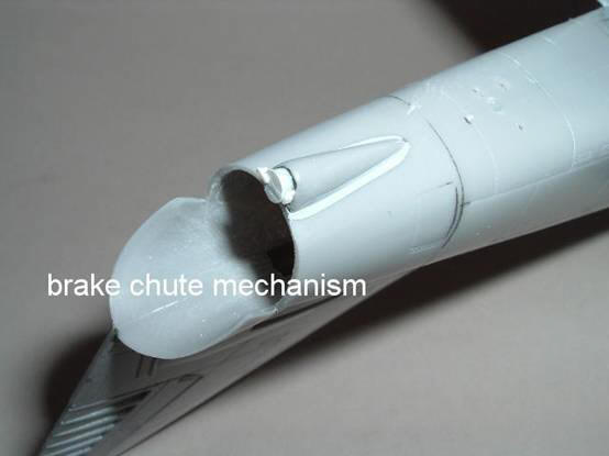 |
The final part of the lower fuselage that
needed work was the parachute brake housing.
I added some more detail to the actuator
mechanism from some plastic strip.
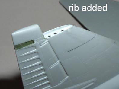
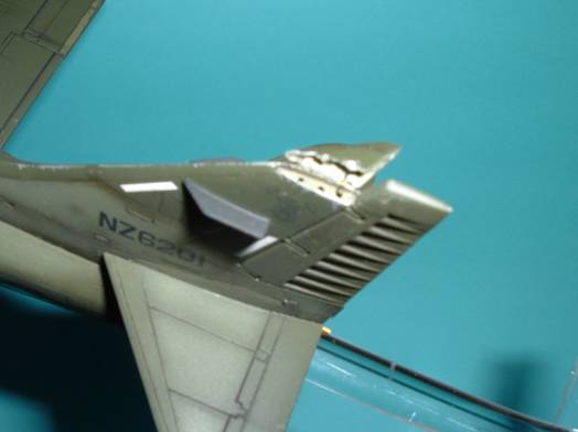
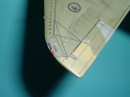
Moving to the upper fuselage, I still had
some work to do on the fin. The pictures
showed that the aircraft landed with the fin
tip hanging over the right side of the fin.
This would necessitate the removal of the
fin tip and adding some interior detail to
the fin itself.
A rib was added to the inside of the fin
after the edges were scraped down to a
thinner section. A scalpel was then used to
create a jagged edge to simulate torn metal.
A similar effort was applied to the fin tip |
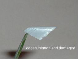 A
similar effort was applied to the fin tip A
similar effort was applied to the fin tip |
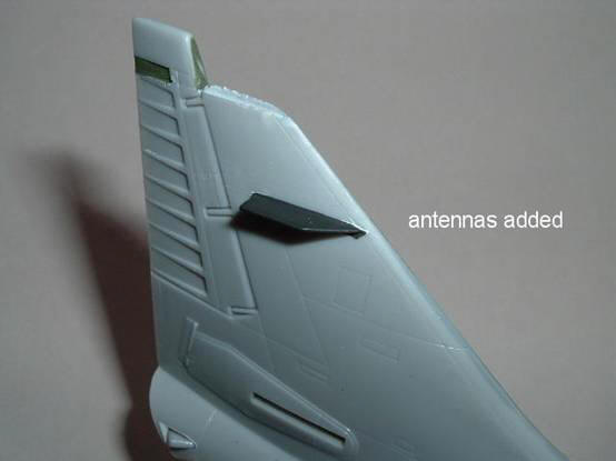 |
The addition of the VOR antennas either side of
the fin completed work on the tail.
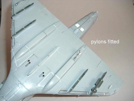
At this point I returned to the wings. I glued all
the pylons to the wings and ran a bead of Mr
Surfacer 500 around them. Once dry a cotton bud
soaked in methylated spirits was used to clean off
most of the Mr Surfacer and fill any small gaps.
NZ6201 was carrying an empty AIM-9 rail and
centreline drop tank on the flight of 20 March. I
decided to add a little interest to the lower
fuselage by adding the pylon sway braces and the
ejector pistons to each pylon.
I used a rotary tool
to open some holes in the base of the pylons. To
this was added some plastic strip and some discs
using a punch and die set. I also added the
electrical ‘umbilical’ to the rear of each pylon
using some fine copper wire.
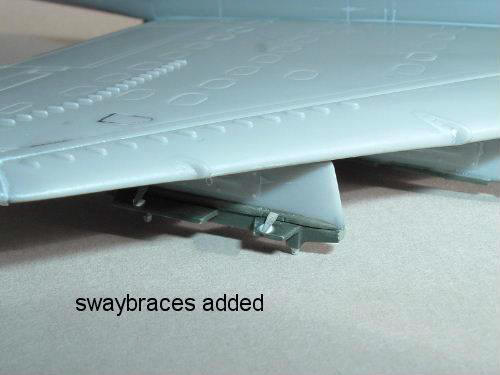
I made the pylon sway
braces from some soft drink can aluminium and
plastic discs punched out with a punch and die set.
Construction was
rapidly nearing an end. I masked the canopy and
primed the model to inspect it for any flaws or
blemishes. Satisfied, I moved onto the painting.
Painting
I sprayed a coat of
Testors FS 34709 overall to begin with. My
references showed that the aircraft exhibited a very
starkly weathered airframe resulting in a ‘patchwork
effect. I lightened the dark green with some white
and a dash of yellow and sprayed the masked off
panels with the new shade. The result looked a
little too stark so I softened the effect by
spraying a darker shade freehand along the panel
lines. I didn’t want to blend the border though,
merely to soften the colour transition a little.
The radome was masked and sprayed black at this
point.
My references stated that this aircraft featured a
port aileron, nose gear door and starboard slat in
the previous “Euro I” grey scheme that the overall
green scheme replaced. My references were not
conclusive about the nose gear door or aileron, so I
painted them “Euro I” scheme. I did have however a
front on shot taken on the day of the incident. I
was not convinced that the slat was in the old
scheme so this was painted in the ‘faded’ green.
I also
picked out various wing access panels in a faded
green to add interest, but not based on any evidence
whatsoever!
Th model was then given a gloss coat in preparation
for decals.
Decals
I used the Gekko
Graphics sheet on this kit. These decals are
superbly printed and performed flawlessly. I
experienced some minor silvering, however that was
due entirely to poor surface preparation on my part.
The sheet allows you to build up to six machines and
is thoroughly researched, and even includes
conversion notes pertaining to the Hasegawa kit.
I was initially
concerned that since these decals were designed to
fit the Hasegawa kit,
I might have problems with the wing walkways.
My concerns were
unfounded as they fit the kit beautifully.
I did have to apply
several applications of Microsol to the outboard
walkway decals in order to get them to conform to
the many small vortex generators. Eventually, after
about eight applications I was happy !
Weathering
Now for the fun part!
I applied a dark brown wash to the panel lines. This
was then removed with a cotton bud. Several streaks
were added ranging in colour from black to reddish
brown. Once satisfied, I gave the kit a coat of matt
varnish. I now used powdered pastels to apply small
graphite streaks behind control surfaces and the
vortex generators at the wing tips. I applied black
pastel to the area around the cannon ports as well
as streaking back from the shell ejector ports.
Another matt coat was applied to seal the pastels.
It was now time to
remove all the canopy and radome masking and add all
the delicate bits. The fuselage centreline tank was
atached as was the AIM-9 rail. The lower rotating
beacon was added as were all the pylon sway braces.
I also glued the clear wingtip lights into their
previously drilled holes. The lights were made from
clear sprue. The upper beacon (red) and the High
Intensity Strobe Light (HISL) was added. This was
made from clear sprue suitable sanded to shape then
dipped in Future. The little probe in front of the
windshield and fin tip was was glued in place with a
small electrical cable added to add interest ( I
don’t think there are actually any cables here in
real life!)
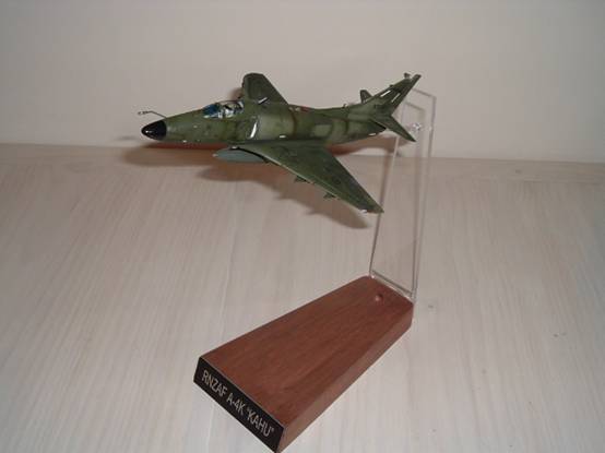
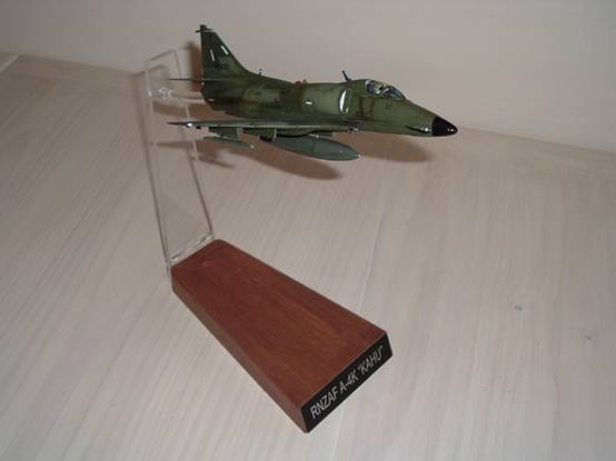
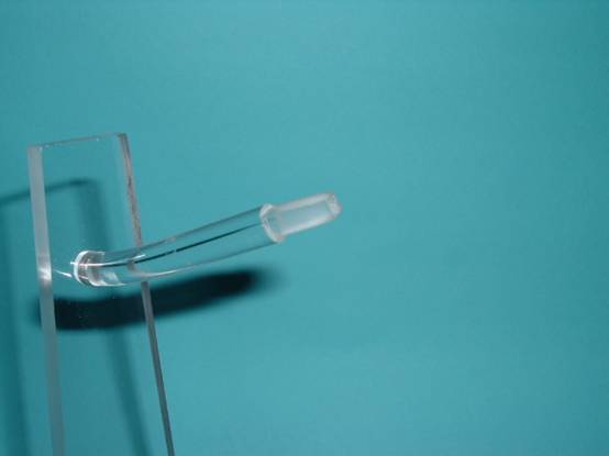
He model is mounted on a 10mm acrylic rod that is
inserted into a perspex back plate, which in turn is
screwed into a Jarrah base. The rod is ‘keyed’ to
fit into the exhaust which has plastic strips glued
inside to receive the rod.
The Hobbycraft kit
builds quickly and easily into a fine replica of the
Skyhawk. I still have several RNZAF Skyhawks to
build, and I will be using the Hasegawa kits as
there is much less manufacturing required. Having
said that, the majority of the additions were easily
accomplished and apart from the decals and pilot
figure (Hasegawa), which was taken from the spares
box, I used no after market detail sets which I
found very satisfying.
I would like to thank the following for their
assistance. They helped provide very useful
reference material to complete this project.
Click the thumbnails
below to view larger images:
Model, Images and Text Copyright
© 2004 by
Anthony
Papadis
Page Created 23 September, 2004
Last Updated
29 September, 2004
Back to
HyperScale Main Page |
 Home
| What's New |
Features |
Gallery |
Reviews |
Reference |
Forum |
Search
Home
| What's New |
Features |
Gallery |
Reviews |
Reference |
Forum |
Search