|
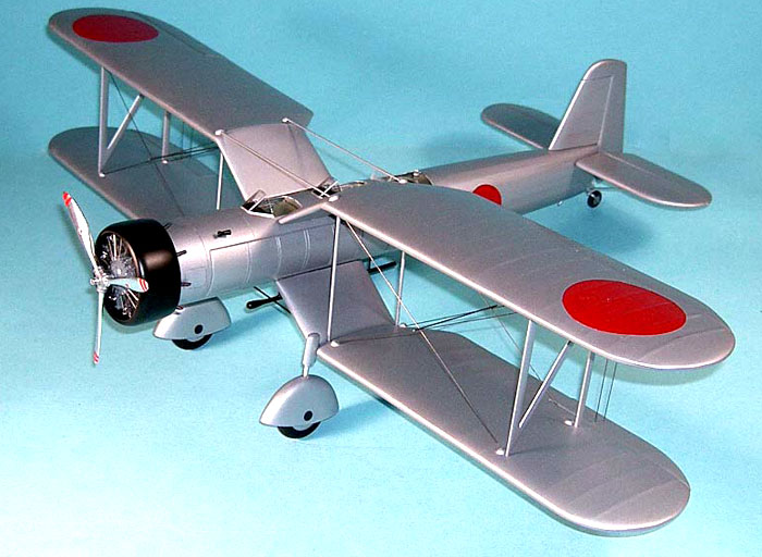
1/32 scale Nakajima B4N1
or
How to Scratch-Build a Model Having Only One Photo and No Text
|
 |
|
Nakajima B4N1 |
by Frank Mitchell

HyperScale is proudly
sponsored by Squadron.com
Note to Rivet-Counters (You know who you
are): Reading this article could bring on cardiac
palpitations, sweating, and significant anxiety. My considered medical
advice would be to take two aspirins, go read something that provides
great detail on a 109 or something, and call me in the morning.
This model had a long gestation period, in fact,
close to 30 years.
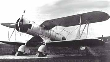 In the early 1970s, Bob Mikesh gave me a picture of
an experimental Japanese torpedo aircraft dating from the 1930s. He
thought it would make an interesting model and would try to get further
information. In the early 1970s, Bob Mikesh gave me a picture of
an experimental Japanese torpedo aircraft dating from the 1930s. He
thought it would make an interesting model and would try to get further
information.
Over the next 10 or so years, he, Lloyd Jones, and a few
other people all tried to come up with more, but that one photograph
(see pictures) is all that could be found. At one point, in the
mid-1980s, Bob asked a friend of his in Japan to see what he could do,
and the friend drew up a three-view drawing, but was able to add very
little additional information.
Both Bob and I saw all kinds of problems
with the drawings, so back into the file cabinet it went. In early
January this year, I ran across the file and decided that if anything
was ever going to be done, it needed to happen before I got too old to
see the parts.
I knew the aircraft’s designation and that it was a
one-off in 1932. I also knew its basic dimensions, that it was a
three-place torpedo bomber, and that it was underpowered. Since no other
photos had ever turned up, that was about it. (Until, of course, this
article appears, at which point I will receive 47 contemporary detailed
photos and drawings including the color of the test pilot’s shorts.)
However, the shape of the thing was so intriguing that, after a few
telephone conversations with Bob, I developed a set of drawings of my
own incorporating what little we knew, and the small bits of information
that had surfaced over the years.
There is obviously a fair amount of conjecture in
the model, but it is truly amazing what one can determine from one
photograph if you have the help of some very knowledgeable people.
The model was built pretty much in my standard way,
but because of the unique shape of the wings, they received priority
because unless they worked, there wouldn’t be any point dealing with the
rest. The photos will help to illustrate everything.
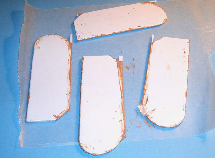
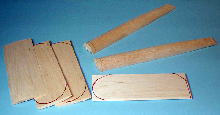
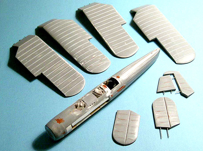
The first step was to prepare molds for the wings,
tail, cowling, and fuselage.
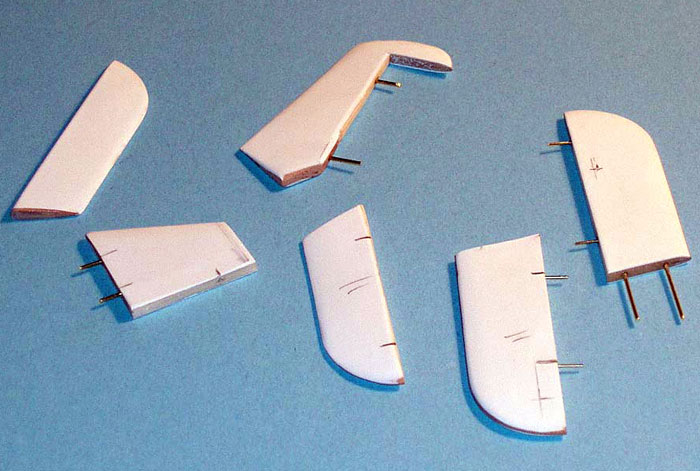
I carved four wings, because having the balsa
inside the plastic outer skin would make for much stronger attachments
to the fuselage and for the struts. The tail was done in basswood in two
pieces, the stabilizer and fin/rudder. The fuselage was composed of four
pieces: the forward section (from about the middle of the gunner’s
cockpit to the nose) was turned from balsa on a small lathe while the
rear portions were carved. The parts for each side were glued together,
but the two halves were not joined until later. The cowling was turned
from basswood.
All the parts were vacuum-formed in styrene, after
which they were cut from the plastic and the edges sanded to get as good
a match as possible. The balsa fuselage molds were then glued together.
Click
the thumbnails below to view larger images:
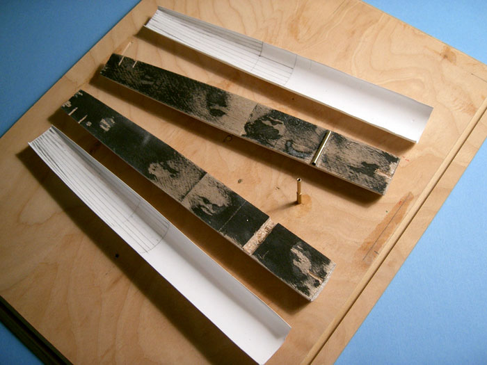
The next step was the building of the jig/building
board that is visible in a number of the photos. Although a jig is
useful in most any major conversion or scratch-building project, it was
essential in this one. There is no other way I could see of getting
those x-wings lined up and square without one.
Each wing root was made from two pieces of balsa
sheet. Each piece had grooves filed that would carry a piece of plastic
tubing through which brass wire would be placed. This wire went into
holes in the wing and the fuselage. A fair amount of time went into
making sure that the wings would be square to the fuselage, and that the
wings were correctly spaced and even. Scrap pieces of balsa were glued
to the jig to make sure that the wings would be properly spaced no
matter how many times I had to put them in or take them out of the jig.
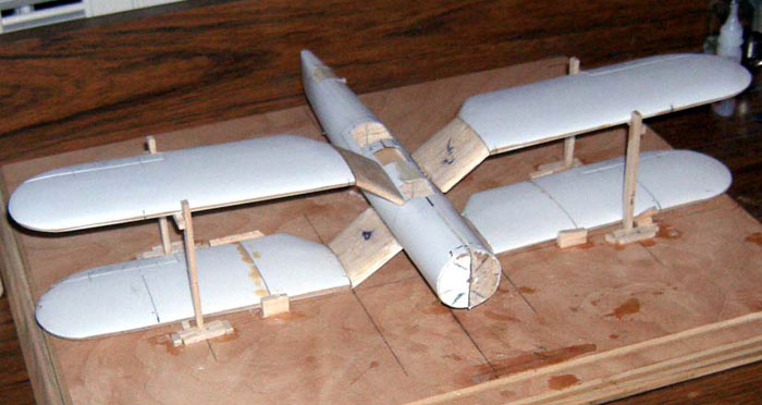
Once I was satisfied with the wing placement, the N-struts and smaller,
inboard straight struts were made and fitted. The final pieces here were
two small brass struts that run from wing to wing above the cockpits.
The ailerons on all four wings were then cut out
and pinned with brass wire.
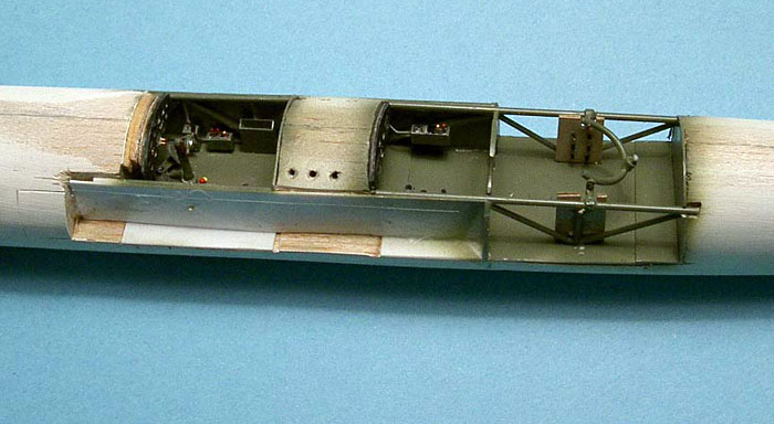
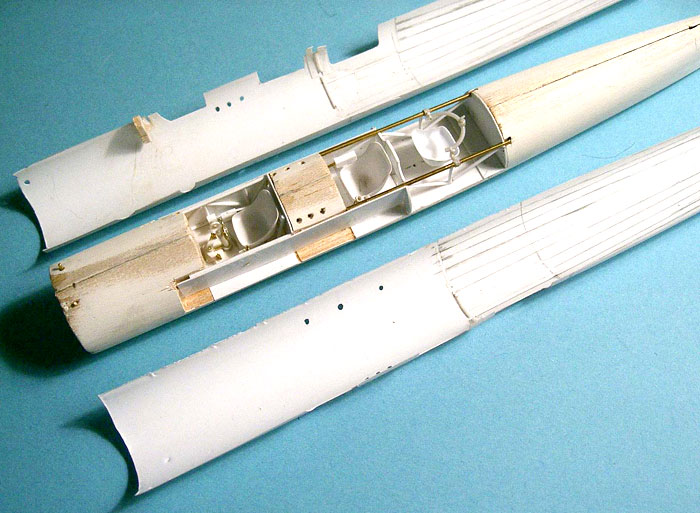
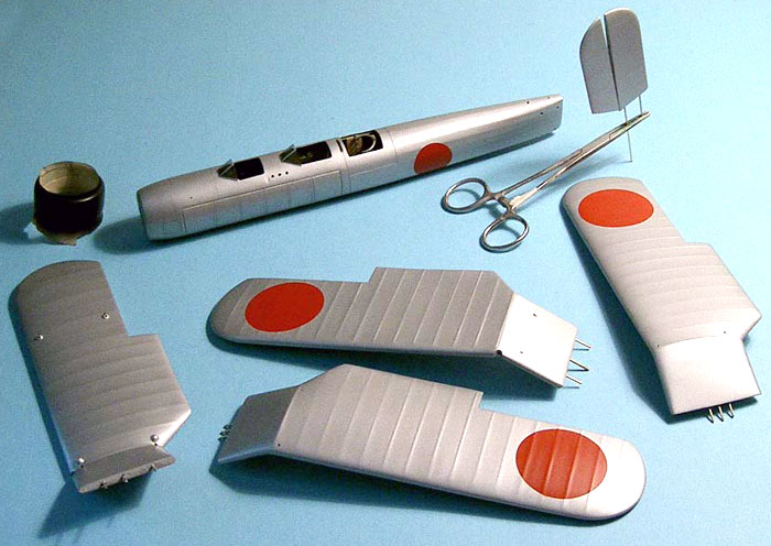
Since I couldn’t make much further progress without
the fuselage being more complete, it was removed from the jig and the
interior detailing began. Nothing much exciting, just working one’s way
through all three cockpits taking my best guess as to what they
contained, with some help from some Maru Mechanics covering
similar-vintage Japanese aircraft.
Click
the thumbnails below to view larger images:
Once that process was complete, the tail surfaces
had their plastic coatings added, and as with the wings, all movable
surfaces were cut apart and pinned with brass wire. The fixed portions
were then fitted and pinned to the fuselage with the aid of the jig.
They would not be glued until painting was complete.
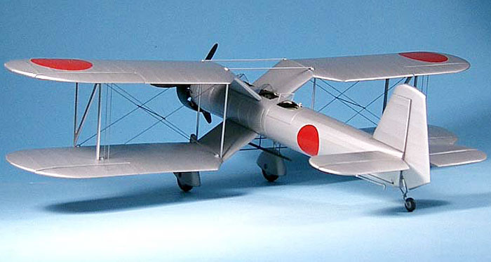
The semi-external fuel tanks run along the sides of
the fuselage. These were done by simply cutting those areas from the
fuselage sides. The cut pieces will be replaced in their openings after
some sanding and scribing are carried out.
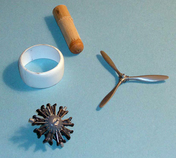
I used a Williams Brothers engine and a propeller
stolen from a 32nd Oscar kit.
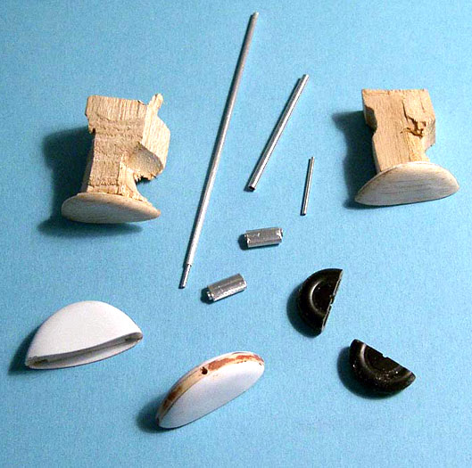
The main landing gear had its own set of problems
in that it is mounted on the leading edge of the wings at the angle
where the inverted gull stops. Molds were made for the right and left
sides of the large wheel fairings and these were formed using
heat-and-smash. These were assembled around a horizontal, shaped piece
of 1/8th balsa. This would contribute strength as well as a
handy place to mount the wheel. The wheel (singular) was found in the
scrap box. It was cut in half so that the two halves could be glued onto
the balsa inside the fairings. The struts and their associated mountings
were made up from brass and aluminum tubing; notches and holes were
placed in the wing to mount the completed gear.
The tail wheel was also found in the scrap box and
its struts were also made up from brass wire and tubing.
There is a structure under the fuselage which I
assumed was a mount for the torpedo as well as horizontal struts running
from wing-to-wing. That made sense because they would match the two on
the upper wing above the cockpits. Brass wire and a piece of plastic
sprue were used to make all this.
At this point, everything was shot with automotive
lacquer primer and the usual routine of priming, sanding, puttying, and
priming began and continued until I was happy.
Although I have tried a number of ways to simulate
fabric covering, I tend to come back to the long and messy method I used
here. That is the application of very thin and narrow strips to the
surface, then apply putty along the edges of each strip. This is
followed by sanding, mostly with the fingertips; the sanding is done in
two stages: First, it is chord-wise, between the strips, and that
is followed by sanding across the strips, again using the tips of
the fingers. The result is a series of “ribs” and “stringers” with only
a small “indentation” between them, which I think gives a fair
representation. A small amount of scribing was done on the metal areas
of the fuselage and the gas tanks.
After this was accomplished, some details needed
attention:
·
The landing hook was made from brass wire, as were two
struts that run between the tops of the upper wings.
·
The individual exhaust stacks were made by gluing
extensions to the pipes provided by the Williams Bros kit so that they
protruded from the cowling the correct distance.
·
18 small protrusions (made by heating-and-smashing over a
round mold) that cover the insert point of each flying/landing wire were
added to the wings very near to the attachment point of the wing
struts. Four others were made to cover the attachment point of the two
upper horizontal struts running between the wings.
·
The windscreens were molded from clear vinyl over a simple
wooden mold (front two), and a flat piece of plexiglass (rear).
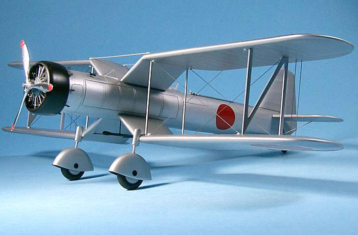
After a final coat of primer, the model was shot
with an old faithful brew I have used for years.
 It is made by throwing
a bottle of Testor’s flat aluminum into a larger jar and adding about
equal amounts of Floquil Flat finish and lacquer thinner. It is made by throwing
a bottle of Testor’s flat aluminum into a larger jar and adding about
equal amounts of Floquil Flat finish and lacquer thinner.
These
proportions vary with my mood, but if the humidity is low, I might throw
in a little more Flat Finish.
Gives a very nice even finish.
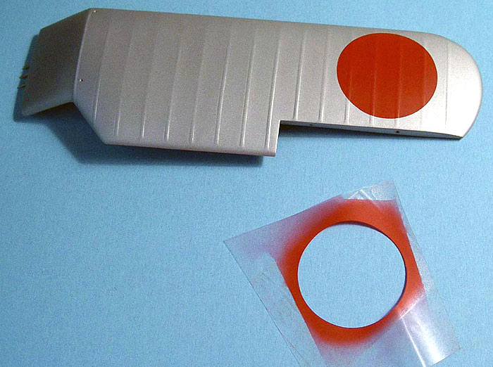
The
national markings were sprayed on using masks of prepared frisket.
After all this, the whole thing was covered with a fairly generous spray
of the Floquil Flat Finish that had only a small amount of lacquer
thinner added. The only decals are black circle covering what I assume
are axle access doors on the wheel pants.
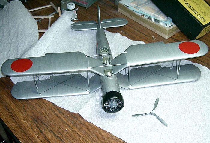
The prop was covered with aluminum foil and the
backs of the blades were painted flat black.
It is always interesting and (and very satisfying)
that, after all that work, final assembly usually only takes a couple of
hours. In this case, most of the time was spent on the flying/landing
wires. I used .015 stainless wire for those.
This was an interesting project. It combined the
efforts of others and a fair amount of guesswork plus a bit of trial and
error on the wing construction. It is also one more off the
“I-am-going-to-build-that-someday” list.
Model, Images and Text Copyright ©
2004 by Frank Mitchell
Page Created 03 June, 2004
Last Updated
03 June, 2004
Back to
HyperScale Main Page |
 Home
| What's New |
Features |
Gallery |
Reviews |
Reference |
Forum |
Search
Home
| What's New |
Features |
Gallery |
Reviews |
Reference |
Forum |
Search