|
Classic Airframes' 1/48
scale
Messerschmitt Bf 109D
by Brett Green
|
 |
|
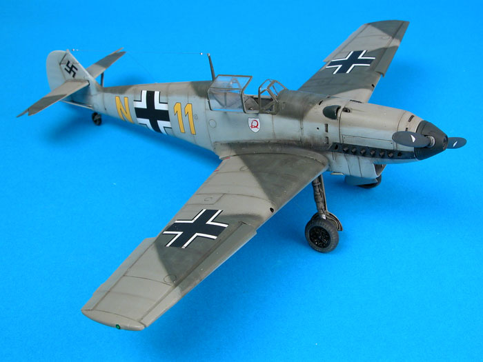
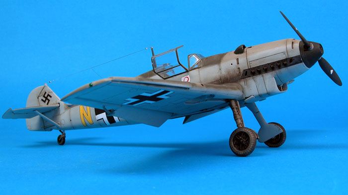
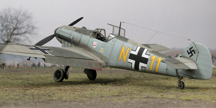
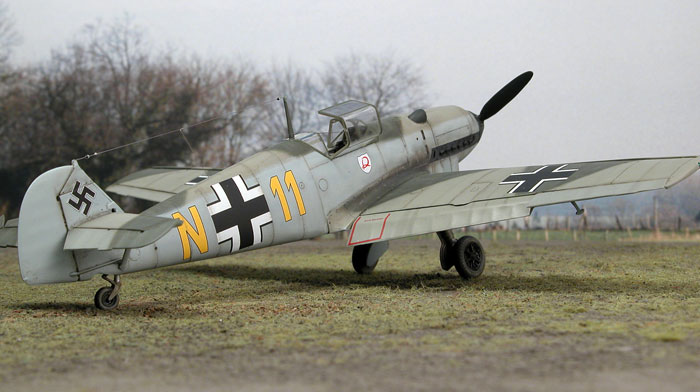
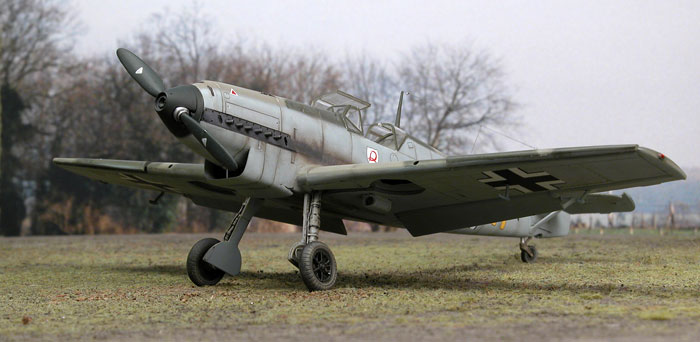
Messerschmitt Bf 109D Night Fighter
11.(N)/JG2, Trondheim-Vaernes, Norway, 1940 |

Classic Airframes' 1/48 scale Messerschmitt Bf 109 C/D is
available online from Squadron
For a detailed examination
of the kit contents,
see my in-box review elsewhere on HyperScale
Although modellers have a large choice of good quality Messerschmitt
Bf 109E, F, G and K kits, the situation has been fairly grim for fans of
the early Jumo powered prototypes and early production models.
Hobbycraft's 1/48 scale kits are widely available and inexpensive, but
they are seriously flawed in terms of accuracy. Problems include too
shallow and misplaced gun slots, incorrectly positioned carburetor
intake scoop, inaccurate panel lines and cooling slots on the cowling,
poorly shaped and poorly detailed radiator intake, very poor Schwartz
propeller, short wing slats, undersized canopy (and one-piece too),
cockpit configuration more typical of a later model and some 109E
attributes on the fuselage.
Classic Airframes' Bf 109C/D in the box
Classic Airframes continues its family of Jumo 109s with a new 1/48
scale Messerschmitt Bf 109C/D kit. This offering shares the basic
components with the recent Classic Airframes Bf 109 A, with new parts
included for the major characteristics of these later models.
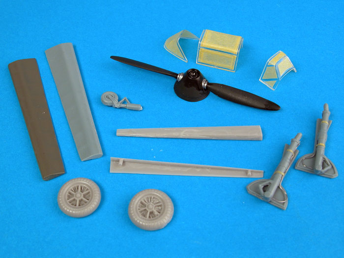
Classic Airframes' 1/48 scale Bf 109C/D kit comprises 34 parts in
grey styrene; 17 parts in grey colored resin; a photo-etched fret; 3
clear injection molded parts; printed clear acetate sheet (instruments);
instructions; plus a decal sheet and painting guide for four aircraft.
In common with the Bf 109 A kit, the plastic parts are absolutely first
rate.
Moulding quality is excellent, and the highly polished finish does
not reveal any moulding imperfections on the exterior surfaces. This
shiny surface will be especially useful for modellers who plan a bare
metal finish for their Bf 109. Panel lines are crisply recessed, and
fabric control surfaces are quite subtly done.
The main differences between the 109 A kit and this new release are
the engine cowl and the wings. The resin cowl is cast with the ejector
exhausts in place (the 109B cowl is also included), while the wings are
equipped with the short leading edge slats.
Parts Preparation
Careful preparation is the key to a successful and
enjoyable project when building any limited-run kit. Although the
surface quality and detail of Classic Airframes' smooth plastic parts
are the equal of many of today's best mainstream manufacturers, absence
of locating pins and the inclusion of resin parts means that clean-up
and regular test-fitting is essential.
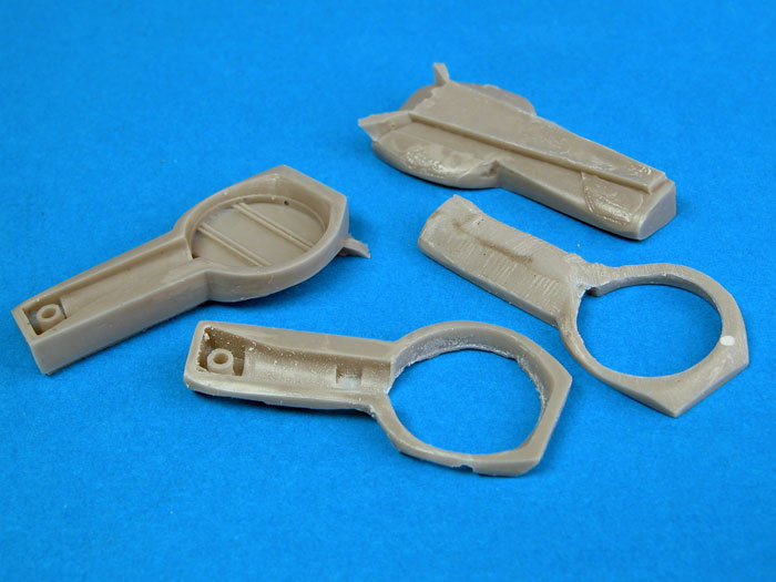
I started by preparing the resin parts. These are
beautifully cast and superior to the detail moulded onto most
conventional plastic kits.
This time I used a motor tool fitted with a cutting
wheel to quickly dispatch the casting blocks. Take care though - this
method kicks up a lot of dangerous resin dust. I wore a ventilator mask
and ran an extension cord outside to minimise the risk to both myself
and my family.
I also took a different approach to the wheel wells
compared to the 109 A kit that I built recently. I ground off the roofs
of the wheel wells, based on the theory that the shallower part might
fit more easily, and that I might not have to thin the inside top of the
wings. I figured that it would be a simple matter to restore the
structural detail directly to the inside of the upper wing.
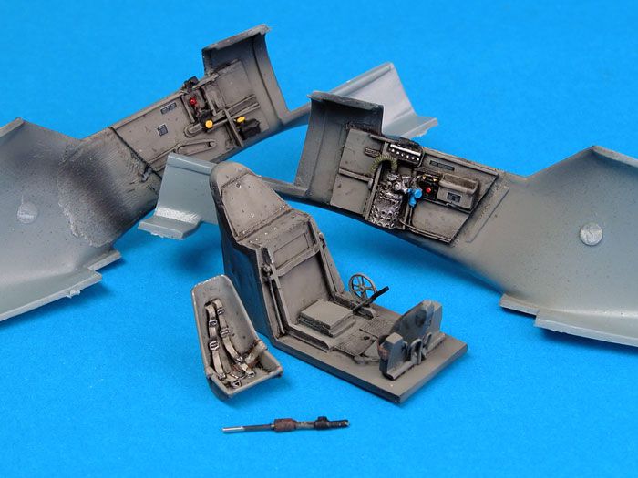
Cockpit
I rushed through construction when I built Classic
Airframes' 109 V4 earlier this year. One of the consequences was that I
was not entirely happy with my paint job in the cockpit. This time I
determined to do better justice to the well-detailed resin interior.
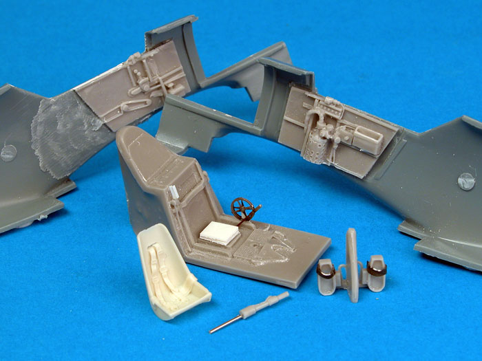
The only after-market part I used was the seat. This was
from Ultracast. The kit-supplied seat is very nice, but the Ultracast
seat with its cast-on harness saved a little time, and does look
terrific.
Click the
thumbnails below to view larger images:
Before assembling the cockpit components I thinned the
fuselage sidewalls. I used a cutting wheel in my Dremel motor tool,
lightly grazing the edge of the wheel along the plastic to remove small
lengths of material at a time. I cleaned up the ragged edges left after
thinning with a coarse sanding stick.
I clumsily managed to knock off the top of one of the
delicate seat rails cast to the rear cockpit bulkhead, so I restored
this feature with two fine strips of styrene.
The bottom of the control column was drilled out and a
length of steel rod was installed to reinforce the join with the
fuselage floor. Toe straps were added to the rudder pedals from lead
foil.
Instead of gluing the trim wheels to the port sidewall,
I secured them either side of a triangle of plastic, then glued the
triangular mount to the fuselage floor beside the pilot's seat.
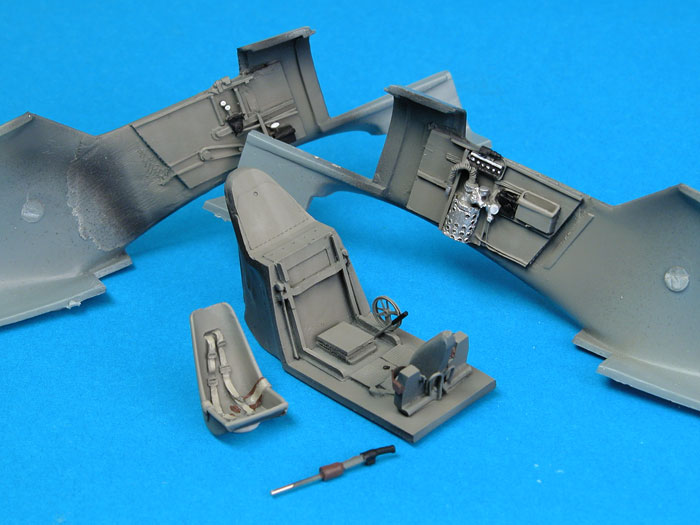
The resin sidewalls were glued to the inside of the
fuselage after carefully measuring against the main cockpit tub
part.
The cockpit paint job commenced with a coat of
Tamiya Flat Black followed by Gunze RLM 02 Grey, mixed with a spot
of Tamiya Flat Base. The 02 colour was misted in several thin coats
onto the parts at a high angle, leaving natural shadow areas in
black. A pin point wash of Raw Umber oil paint was applied to the
edges of structural details and panels, representing grime and wear.
After the wash had dried overnight, details were picked out with
acrylic paints and a fine brush. Chipping was simulated here and
there with a well-sharpened 2B pencil.
I also applied cockpit placards from a Reheat decal
sheet.
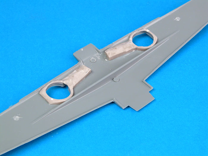
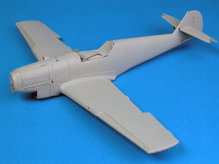
Wheel Wells and Wings
With the tops of the wheel wells ground off,
assembly of the wings was a snap.
The wheel wells were glued onto the bottom wing half
and the top halves were test fitted. A little further sanding of the
top fronts of the wheel well resin was all that was required for an
easy fit.
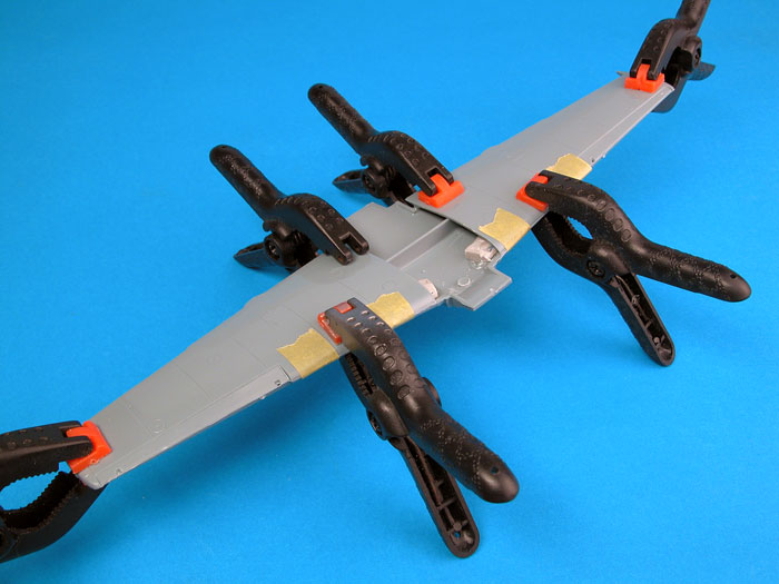
When the wings were glued, clamped and set, the
positions for the wing-mounted machine gun openings were marked in
the leading edges and drilled with a pin vise.
Click the
thumbnails below to view larger images:
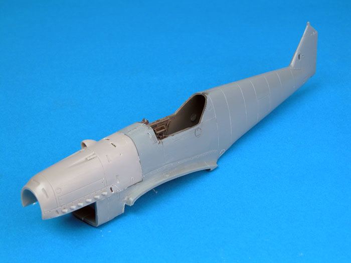
Fuselage and Main Assembly
The balance of construction was similar to the 109 V4.
Before joining the fuselage halves I hollowed out the space on the
fin where the horizontal stabilizer adjusts up and down. This was
achieved by drilling several holes and "joining the dots" with a
sharp hobby blade.
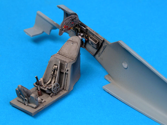
I fitted the instrument panel then glued the fuselage halves
together. When the fuselage halves had set I installed the cockpit
tub from the opening underneath.
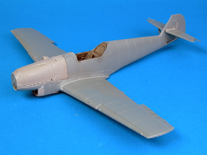
Just to be different this time, I glued the nose parts to the
fuselage before attaching the wing. Somehow I managed to slightly
twist the nose. No excuses - I should have taken more notice of my
own mantra to test fit and test fit some more. As it is, when viewed
from directly above, the nose takes a very slight right turn at the
front of the windscreen. Having now done it both ways, I recommend
attaching the wings before the nose is glued to the front of
the fuselage.
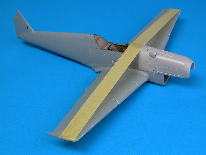
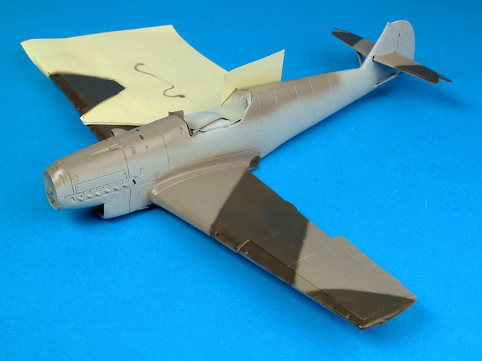
At this stage the wings were offered to the fuselage. The wings are
cleverly designed so that the front centre section forms the top of
the outlet ramp for the radiator. I lightly sanded and test-fitted
the joining surface at the centre rear of the wing several times
until a perfect gap-free fit was achieved. The important thing here
is not to shave too much plastic from the back of the wing centre
section - just sand lightly, test-fit and repeat as required.
Click the
thumbnails below to view larger images:
With a nice tight fit between the wing and the fuselage, Tamiya
Extra Thin Liquid Cement was flowed into the join lines at the wing
root, and the front and rear of the wing assembly. A length of
Tamiya tape was stretched across the top of the model from wingtip
to wingtip to ensure there would be no gaps at the wing root.
Dihedral is set by the wing spar, but Tamiya tape was used to
guarantee a gap-free join at the wing root.
The resin radiator intake includes nicely cast detail for the
radiator face, but even better detail is available on the supplied
photo-etched part. This metal face was glued inside the resin
intake. Reference photos show that the radiator was fitted with two
diagonal and one vertical brace. These were added from fine brass
and steel wire.
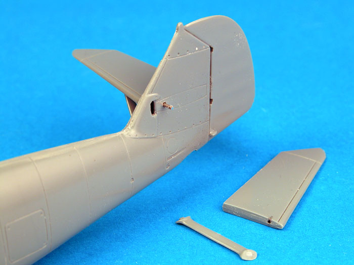
Horizontal stabilizers are supplied without locating tabs. To
reinforce this join, I drilled holes in the mating surfaces of the
stabilizers and through the fin. A steel pin was inserted to assist
alignment and strengthen the join. Stabilizer struts, parts 25 and
26, fitted perfectly.
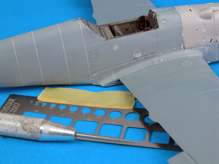
The electrical socket and oxygen filler point on the
fuselage are correct for Bf 109 prototypes and the "B" production
variant, but should be relocated aft for the Bf 109 C and D. If you feel
so inclined, this is not a difficult task. I filled the existing
electrical socket and oxygen filler on the starboard side with Gunze Mr
Surfacer and sanded them smooth. New points were then scribed into the
correct positions using Techstar templates and a pointed scriber. I ran
a small amount of liquid cement in the newly-scribed circles to blend in
the rough edges.
Lengths of copper wire were glued to the bottom of the
empennage representing rudder actuator rods.
The first coat of paint was Tamiya Light Blue. This was
the AS-5 spray can colour, but decanted into a jar and applied with my
Testor Aztek A470 airbrush.
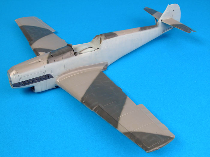
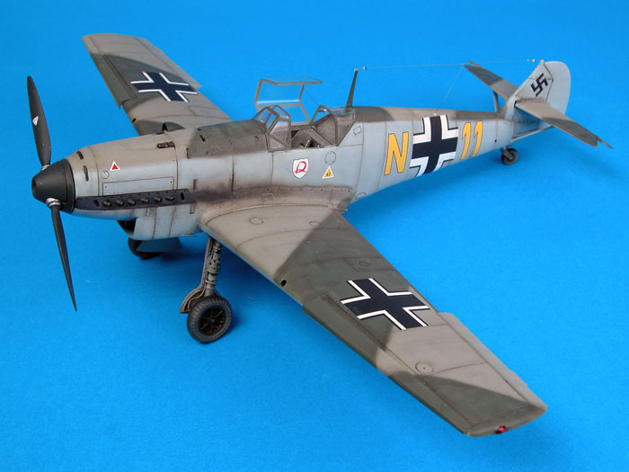
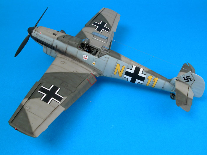
Next, the model received a coat of RLM 02 Grey on the
top of the wings and the spine. The disruptive colour of RLM 71 Dark
Green was sprayed with the aid of self-adhesive paper masks. When the
masks were removed, I sprayed fine lines of RLM 71 freehand along the
camouflage lines to slightly soften the demarcation between the colours.
Click the
thumbnails below to view larger images:
RLM 65 Light Blue was then applied up the fuselage sides
to meet the upper surface camouflage colours.
Paler shades of each colour were mixed and sprayed in fine lines and
random mottles as an initial weathering measure.
The exhaust panels were masked and sprayed Tamiya's
German Grey.
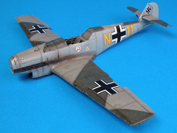
Markings
Markings were sourced from Cutting Edge Decals' CED
48265 "Bf 109D Early Messerschmitts Part 2".
The markings performed perfectly despite the fact
that I had not applied any gloss coat. I simply polsihed the
semi-gloss Gunze finish with a nail buffer, then applied the decals
with the assistance of Micro Set and Micro Sol.
One of the advantages of Classic Airframes' early Bf
109 kits is that, in addition to the attractive marking options
supplied with the kit, there are plenty of after-market decals
available for even more variety.
Weathering
First, Tamiya X-18 Semi-Gloss Black was thinned with
water and run into panel lines.
Then a thin mix of Tamiya Red Brown and Flat Black
was sprayed along selected panel lines. I focused on panels around
the rear and bottom of the engine cowling. Light stains were also
sprayed around the wing roots, and on the bottom of the fuselage
behind the radiator outlet.
A thin wash of Raw Umber oil paint was applied with a fine brush to
a few areas including rivets on the wing root fairing, filler
hatches, fin fairing, gun troughs, fuselage vents, and release
latches.
A silver pencil was used to apply some subtle
chipping on the wing walkways.
A thin coat of Gunze Flat Clear was sprayed over the decals to tone
down the glossy markings.
Finishing Touches
Hydraulic lines were added to the main gear legs from Up
North tin wire, secured with straps of thin Tamiya tape.
Aerial wire is E.Z. Line, a very elastic material that
lessens the risk of drooping or breaking after installation.
E.Z. Line was also used for the canopy restraining wire.
I found that the resin slats sat more naturally when the
mounting pegs were thinned and trimmed.
This is the second time I have built one of Classic
Airframes' 1/48 scale Jumoschmitts, and it was as enjoyable this
time as it was the first.
Classic Airframes' Bf 109C/D kit is impressively
detailed, fits together well, has some very attractive marking options
and is by far the most accurate 109C/D kit available today.
The only problem I encountered - slightly misaligning
the engine cowl - was entirely my fault and simply reinforces the
importance of continually test-fitting.
If you do not object to a little extra time preparing
resin parts and confirming alignment during construction, there is
nothing terribly daunting about building one of these excellent kits.
The biggest disadvantage is probably the limited
availability of Classic Airframes Bf 109s. With their small production
runs, once they're gone, they're gone. I am advised that the
manufacturer has already sold out of the 109A kit (although distributors
and retailers should still have some in stock).
If you think you'd like to build one of Classic
Airframes' 1/48 scale Messerschmitt Bf 109C/D kits, you'd better get one
now!
Click the
thumbnails below to view larger images:
Model,
Images & Text Copyright © 2006 by
Brett Green
Page Created 07 April, 2006
Last Updated
10 April, 2006
Back to
HyperScale Main Page |
 Home
| What's New |
Features |
Gallery |
Reviews |
Reference |
Forum |
Search
Home
| What's New |
Features |
Gallery |
Reviews |
Reference |
Forum |
Search