|
Classic Airframes' early Bf
109 in 1/48
Augsburg's First
Eagle
by Brett Green
|
 |
|
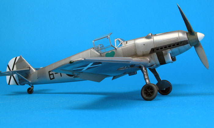
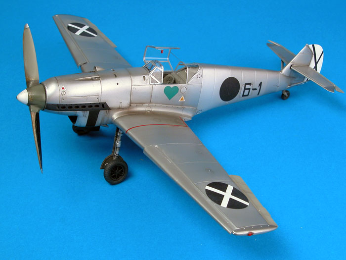
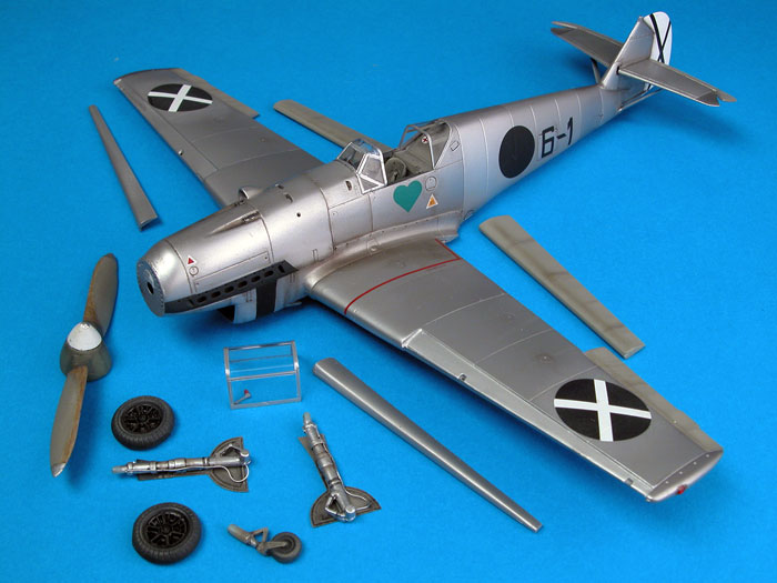
Messerschmitt Bf 109 "6-1" |

Classic
Airframes' 1/48 scale Messerschmitt Bf 109 A is available online from Squadron
Early Bf 109 Prototypes and Production Variants
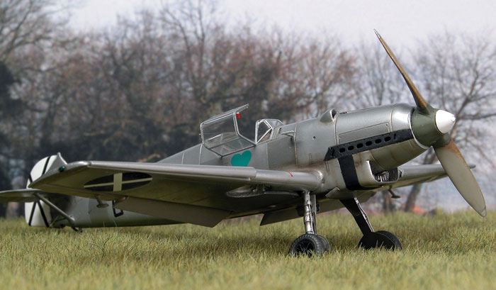
The earliest Messerschmitt Bf 109 variants were
fitted with the Jumo 210 engine. Compared to the the later and more
familiar Daimler-Benz equipped versions, the Jumo powerplant rendered a
very different profile to the nose of these early 109s.
The first Bf 109 to be fitted with the Jumo engine
was the second prototype, the V2, which differed from the first
production models in a number of respects. The V2 was unarmed, featured
a streamlined upper cowl, different spinner design, large main wheels
requiring a long "bump" on the top of the wings (similar to the later
model Bf 109s such as the G-10 and K-4), small tail wheel with no oleo
scissor and other detail variations.
The next prototype, the V3, was fitted with cowl
armament and a revised windscreen, but was otherwise similar to the V2.
It is generally acknowledged that the V3 was the prototype for the Bf
109A series.
The V4 introduced the production-style engine
cowling and tail wheel, narrower main wheels (with the upper wing bump
deleted), and a separately-framed quarter panel on the bottom of each
side of the windscreen. Other changes included the provision for a
centre mounted machine gun firing through the propeller hub, relocation
of the pitot tube from the side of the fuselage to under the wing, and a
new style of oil cooler mounted close to the port-side wheel well. The
Bf 109 V4 was the prototype for the Bf 109B production series. A
variable pitch metal two-bladed VDM propeller assembly was planned for
the Bf 109B, but delays in supply meant that the first production
machines were fitted with the wooden Schwarz propeller.
It should be pointed out that there are
discrepancies between reference sources regarding identification of some
of these prototypes and early production models. One recent case in
point relates to the first production machines. Conventional wisdom has
been that the Bf 109B was the first variant to reach production status
but recent sources, including Lynn Ritger's new Bf 109 "Modellers'
Datafile", suggest that there might have been a small Bf 109A series
production run. Regardless of the label, however, these early production
machines varied little. For example, the main feature suggested as
distinguishing the Bf 109A from early Bf 109B production machines is the
location of the underwing oil cooler.
In service, these "Jumoschmitts"
were relatively underpowered, and the initial armament of two
cowl-mounted machine guns quickly proved inadequate compared to the
emerging generation of European fighter aircraft.
Despite these limitations, however, the
Messerschmitt Bf 109B, C and D dominated contemporary fighters in combat
over the skies of Spain. The Messerschmitt airframe also proved
adaptable, with continual development ensuring that the Bf 109 remained
the Luftwaffe's first-line fighter weapon (although it was undeniably
surpassed by other German designs) for the entire duration of the Second
World War.
Jumoschmitts in Plastic
Although modellers have a great selection of
Messerschmitt Bf 109E, F, G and K kits to choose from, the situation has been fairly
grim for fans of the early Jumo powered prototypes and early production
models.
Hobbycraft's 1/48 scale kits are widely available
and inexpensive, but they are seriously flawed in terms of accuracy,
especially their Bf 109B model. Problems include too shallow and
misplaced gun slots, incorrectly positioned carburettor intake scoop,
inaccurate panel lines and cooling slots on the cowling, poorly shaped
and poorly detailed radiator intake, very poor Schwartz propeller, short
wing slats, undersized canopy (and one-piece too), cockpit configuration
more typical of a later model and some 109E attributes on the fuselage.
Classic Airframes has now come to the rescue of
1/48 scale modellers with the first in their family of Jumo-powered Bf 109
kits. This premiere offering is labeled Bf 109 A, but this undersells
the kit. In fact, you can build the Bf 109 V4, V5 or any early
production machine with long leading edge slats.
For a detailed look at the contents of the box,
click here to view my review of Classic Airframes' 1/48 scale Bf 109 A
kit posted last week on HyperScale.
Parts Preparation
Careful preparation is the key to a successful and
enjoyable project when building any limited-run kit. Although the
surface quality and detail of Classic Airframes' smooth plastic parts
are the equal of many of today's best mainstream manufacturers, absence
of locating pins and the inclusion of resin parts means that clean-up
and regular test-fitting is essential.
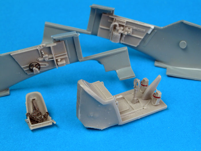
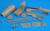
I started by preparing the resin parts. These are
beautifully cast and superior to the detail moulded onto most
conventional plastic kits. A razor saw was used to cut each resin part
from its casting block. A few swipes with a sanding stick was enough to
clean up after the parts were separated.
Extra care is required when removing the engine cowl and
the Schwarz prop from their blocks. Make sure you cut very close to the
casting block in both cases. The casting stubs on top of the wheel well
parts must also be completely removed, and the top of the part reduced
to wafer thinness.
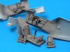
Cockpit
Two sets of cockpit sidewalls are supplied. I chose
the starboard sidewall without the map case and glued it to the
fuselage interior before I realized that the oxygen bottle was not
fitted to this part. I sliced the oxygen bottle from the alternate
starboard sidewall using a sharp hobby knife and glued it into
place.
Two seats are also included. I chose the separately
bagged version, as detail was noticeably better. The photo-etched
harness looked great when assembled and attached to the seat. Foot
straps were cut from lead foil and glued to the rudder pedals.
Click the
thumbnails below to view larger images:
|
|
|
|
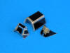
Classic Airframes' resin parts are crisply cast and beautifully detailed
|
|
|
|
Sidewalls were glued to the fuselage interior before painting. Caution must be exercised to ensure the correct location of the cockpit components.
|
|
|
I glued the trim wheels onto a short length of
copper wire, spaced the wheels slightly, then glued the wire axle
into a hole that I had drilled into the sidewall. Test fitting the
cockpit components showed that I had got the position of one of the
sidewalls slightly too far forward, and that the extra width I had
added to the trim wheels would cause them to foul against the trim
wheel mount. I cut the trim wheel mounts from both the seat and the
cockpit floor, and glued one to the trim wheels themselves. I also
thinned some of the detail on the port side of the seat.
Next time I build a Classic Airframes Bf 109 I will
thin the sidewalls before gluing them to the fuselage and I will not
space the trim wheels so far from the sidewall. This should avoid
some of my self-induced complications!
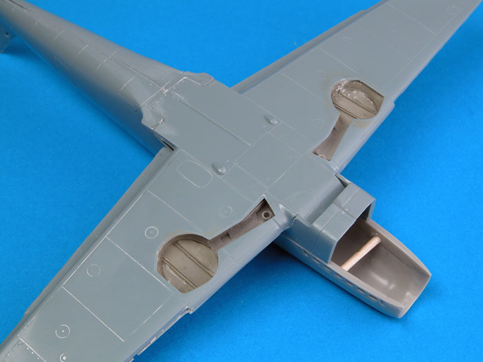
Wheel Wells and Wings
Classic Airframes has supplied attractive resin
wheel wells in the kit. In addition to adding detail, these also
offer positive location for the installation of the main gear legs.
The top of the resin parts should be thinned until
they are almost transparent. In fact, you will note in the photo
below that I have broken through the wheel well ceiling in a couple
of places. These gaps were later filled with super glue.
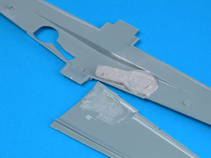
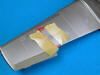
I also thinned the inside of the top of the wings
until a good fit was achieved. Take your time when thinning the top
of the wing to avoid breaking through or melting the plastic - a
real risk if you are using a Motor Tool.
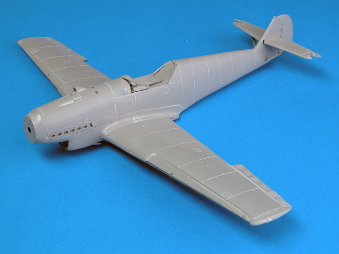
The wing goes together beautifully once the tedious
task of thinning is complete, and the integral wing spar guarantees
the correct dihedral.
Fuselage and Main Assembly
With the cockpit and wheel wells installed,
construction is no more difficult than many mainstream kits.
I fitted the instrument panel then glued the
fuselage halves together. When the fuselage halves had set I
installed the cockpit tub from the opening underneath.
At this stage the wings were offered to the
fuselage. The wings are cleverly designed so that the front centre
section forms the top of the outlet ramp for the radiator. I lightly
sanded and test-fitted the joining surface at the centre rear of the
wing several times until a perfect gap-free fit was achieved. The
important thing here is not to shave too much plastic from the back
of the wing centre section - just sand lightly, test-fit and repeat
as required.
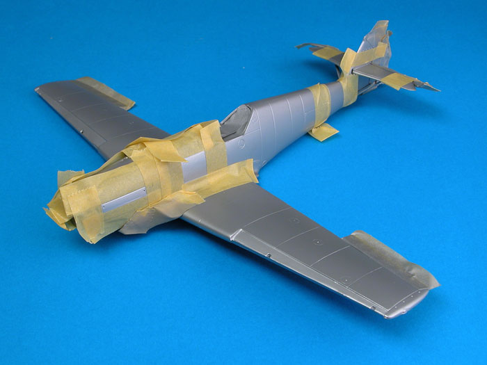
With a nice tight fit between the wing and the
fuselage, Tamiya Extra Thin Liquid Cement was flowed into the join
lines at the wing root, and the front and rear of the wing assembly.
A length of Tamiya tape was stretched across the top of the model
from wingtip to wingtip to ensure there would be no gaps at the wing
root.
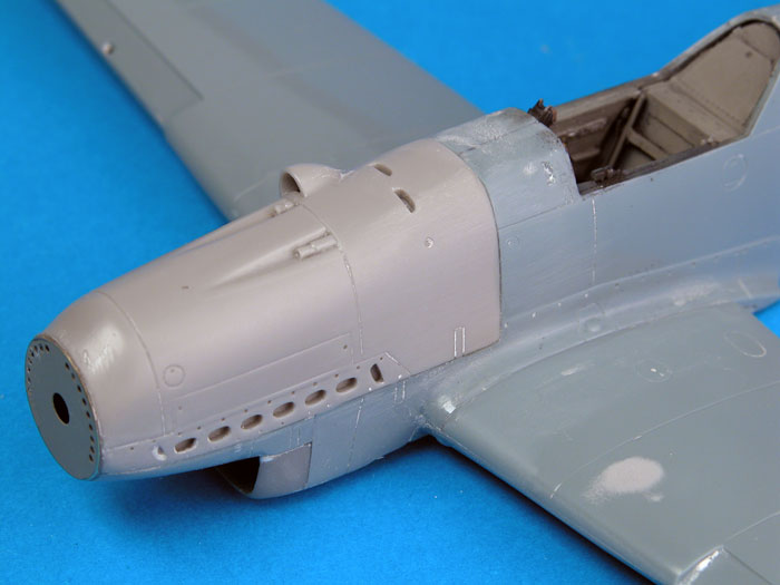
Once these main sub-assemblies had thoroughly set, I
installed the resin engine cowl. Test fitting exposed a tiny step
between the resin cowl and the bottom cowl / rear of the radiator.
Rather than fill this step later, I decided to deal with it now. Two
cocktail sticks were cut to size and glued inside the cowl to
marginally spread the resin part. This eliminated the step. The
upper cowl was set in place using thick super glue before the lower
forward cowl was added to complete the nose.
The result was a gap-free, step free join. The photo
below shows that no filler was required in this important area.
Click the
thumbnails below to view larger images:
|
|
|
|
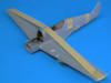
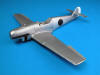
Dihedral is set by the wing spar, but Tamiya tape was used to guarantee a gap-free join at the wing root.
|
|

|
|
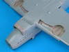
Cocktail stick spreaders were installed to ensure a perfect fit of the resin engine cowl.
|
|
|
|
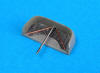
Fine copper and steel wire was used to add braces to the front of the radiator.
|
|
|
|
As can be seen, with sufficient preparation, the fit of the resin and plastic parts is excellent.
|
|
|
|
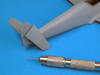
A hole was drilled into the mating surface of each horizontal stabilisers. A metal pin was used to strengthen this join.
|
|
|
I decided not to glue plastic part 20 to the front
of the cowl. I left this part on the sprue and glued the perforated
photo-etched cowl face direct to the nose instead. In my opinion,
this shows off the ventilation holes to better advantage and
improves the fit in this area too.
The resin radiator intake includes nicely cast
detail for the radiator face, but even better detail is available on
the supplied photo-etched part. This metal face was glued inside the
resin intake. Reference photos show that the radiator was fitted
with two diagonal and one vertical brace. These were added from fine
brass and steel wire.
Horizontal stabilizers are supplied without locating
tabs. To reinforce this join, I drilled holes in the mating surfaces
of the stabilizers and through the fin. A steel pin was inserted to
assist alignment and strengthen the join. Stabilizer struts, parts
25 and 26, fitted perfectly.
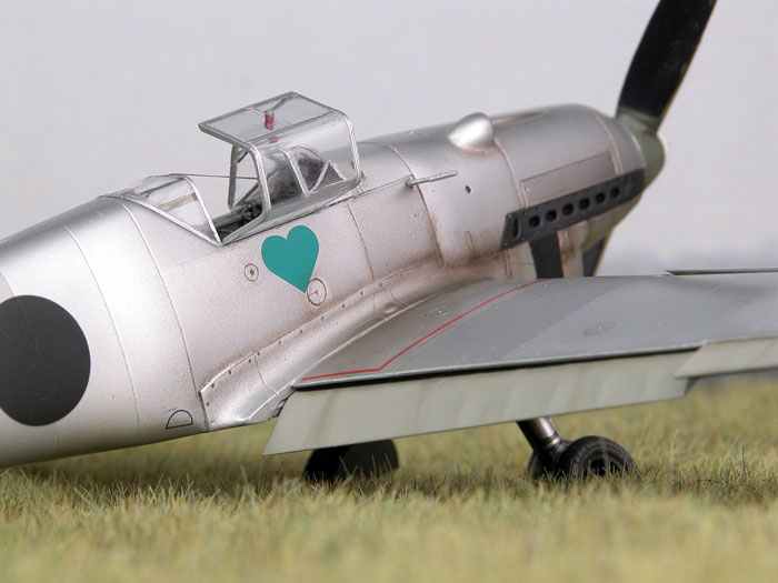
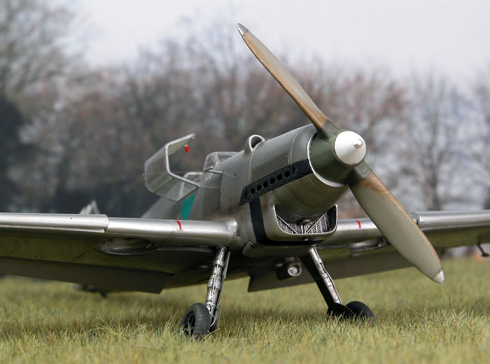
Metal or Paint?
 Close
examination of reference photos from the Spanish Civil War reveals an
ambiguous finish on the earliest Bf 109s. On the one hand, the finish
often displays the distinct irregularity of tone and sheen consistent
with a natural metal surface, but some angles suggest a flat puttied and
painted airframe. Close
examination of reference photos from the Spanish Civil War reveals an
ambiguous finish on the earliest Bf 109s. On the one hand, the finish
often displays the distinct irregularity of tone and sheen consistent
with a natural metal surface, but some angles suggest a flat puttied and
painted airframe.
In his recent book, "Luftwaffe Camouflage and Markings
1933-1945 Volume One", Ken Merrick states that these early Legion Condor
Bf 109s were sprayed in a thin protective finish which was tinted in a
colour similar to RLM 02. The result was a translucent coat that clearly
showed the irregularities of bare metal, but with a greenish tinge.
Even with this information available, however, I had a
great deal of trouble trying to replicate the finish. I first tried to
spray a thin coat of RLM 02 over a natural metal finish. The result just
looked like regular RLM 02. Next, I tried to tint Alclad with Gunze
acrylic RLM 02. Two drops in half a paint cup had no noticeable effect,
while four drops converted the finish to something that just looked like
chalky RLM 02. Three drops in half a paint cup of Alclad still did not
really tint the colour, but it did take the high gloss edge off the
shiny metallic paint. That would have to be close enough!
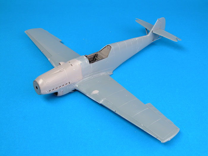
I started by spraying the entire model with Tamiya Grey
Primer, straight from the can. The primer was buffed to a high gloss
with Micro Mesh cloths.
Click the
thumbnails below to view larger images:
|
|
|
|
Very little filler was required before painting. The surface was polished before primer was applied.
|
|
|
|
Tamiya Grey Primer was sprayed onto the model direct from the can.
|
|
|
|
With the primer polished to a high gloss, control surfaces were painted RLM 02 Grey and masked.
|
|
|
I assumed that fabric surfaces would be primed, so
control surfaces were sprayed with Gunze RLM 02 Grey, except the rudder
which received a coat of Flat White. These painted surfaces were then
masked in preparation for the metallic finish.
Gunze-tinted Alclad was loaded into the paint cup of my
Testor Aztek A470 airbrush and applied in an overall coat. The result
was a perfectly blemish free, uniform metallic finish. In fact, the
tinted Alclad seemed to be less temperamental than 100% Alclad. I
usually get a few rough patches but had no such trouble this time.
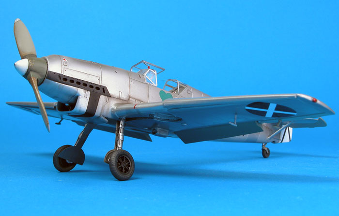
Reference photos show that a number of panels that were
consistently darker than the rest of the aircraft. These panels were
masked and sprayed with Alclad Dark Aluminium. Other selected panels
were masked and sprayed using Tamiya AS-12 Airframe Silver, decanted
into a bottle. This is a suitably ambiguous shade which could represent
either a weathered alloy or a silver painted finish.
Access and filler hatches were masked and sprayed with
the same colour to add a little more variation to the finish.
The exhaust panels and radiator surrounds were masked
and sprayed with Tamiya Flat Black. I then masked off the radiator and
sprayed a 50/50 mix of Tamiya Flat Black and German Grey onto the
exhaust panel at a downward angle. This reinforced the impression of the
deep exhaust holes.
Click the
thumbnails below to view larger images:
|
|
|
|
The basic paint job is finished and awaits decals and weathering.
|
|
|
|
Small access hatches were masked with a dymo-tape template, and sprayed Tamiya Airframe Silver
|
|

|
|
Classic Airframes' decals performed flawlessly.
|
|
|
|
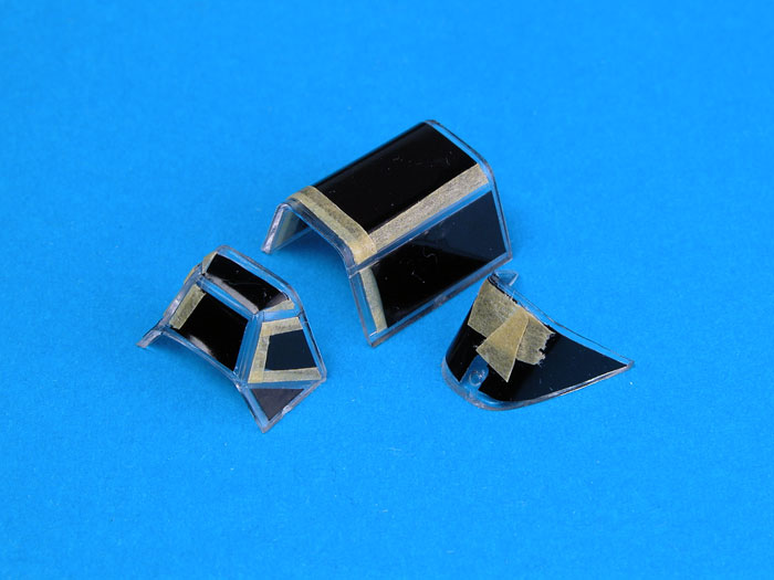
Cutting Edge's Black Magic masks for Hobbycraft's 109B were used as a basis for masking the Classic Airframes canopy. Modifications were required!
|
|
|
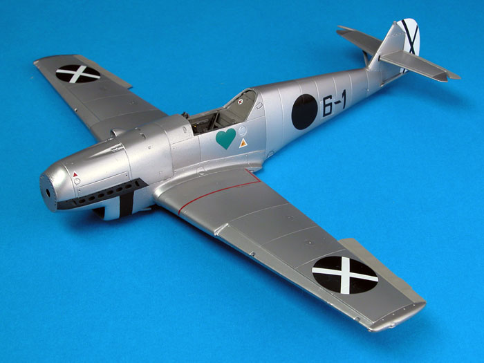
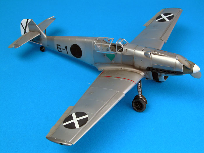
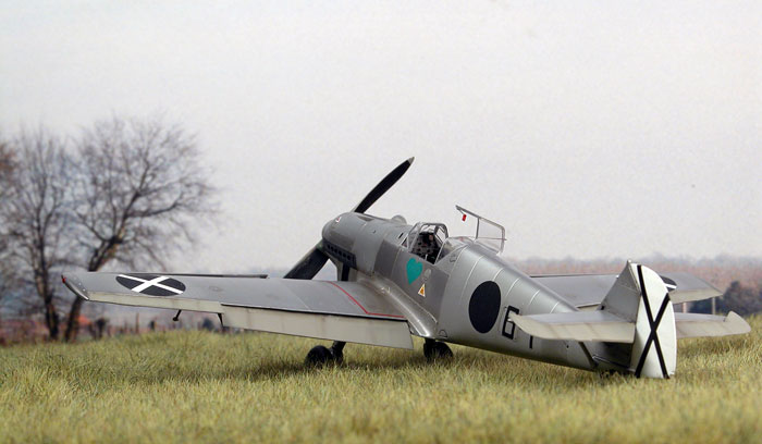
Markings
Although they are not mentioned in the marking instructions,
I used decals supplied for Trautloft's "6-1".
Sources are at odds about this machine (presumably the reason that
this option was not officially included in the kit instructions), but several references suggest
that this machine was actually the Bf 109 V4 sent to Spain for
evaluation. There is also a photo of this aircraft on a web page, "The
Bf 109 in Spain"
http://www.zi.ku.dk/personal/drnash/model/spain/bf109.html , which
displays all the characteristics of either the Bf 109 V4 (which was the
B model prototype), or an early production machine.
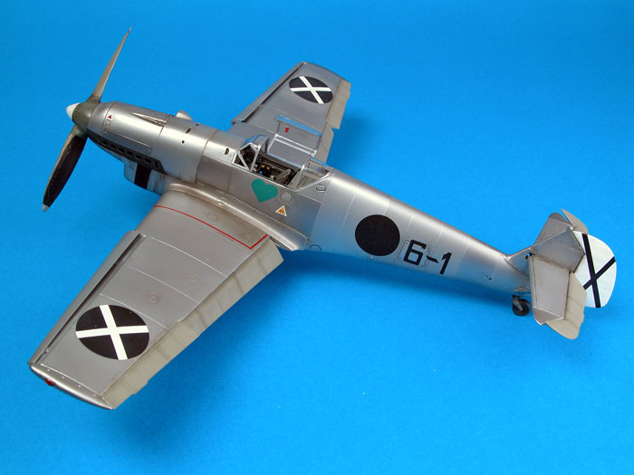
However, one unusual feature of this aircraft is the
installation of the pitot tube on the starboard fuselage side, just
forward of the windscreen. Lynn Ritger believes that "6-1" might
actually be the Bf 109 V3 prototype which was previously
photographed in Spain as "6-2" (with a crude skull and crossbones
painted under the canopy), but renumbered and retrofitted with the
new style wing, canopy, engine cowling, propeller and tail wheel.
On the other hand, "6-1" may be another prototype or
an early production machine that had its pitot tube relocated for
some reason lost in the passing of the decades.
Regardless of ultimate identification, however, this
is an attractive and interesting machine.
Classic Airframes' decals performed flawlessly in
concert with Micro Set and Micro Sol.
Weathering
I kept weathering light.
A thin mix of Tamiya Red Brown and Flat Black was
sprayed along selected panel lines. I focused on panels around the
rear and bottom of the engine cowling. Light stains were also
sprayed around the wing roots, and on the bottom of the fuselage
behind the radiator outlet.
A thin wash of Raw Umber oil paint was applied with
a fine brush to a few areas including rivets on the wing root
fairing, filler hatches, fin fairing, gun troughs, fuselage vents,
and release latches.
A thin coat of Gunze Flat Clear was sprayed over the
decals to tone down the glossy markings.
Finishing Touches
I used the resin Schwarz propeller for Trautloft's
aircraft. The shape looks good but I cut too much of the spinner
base off when removing the part from its casting block so I beefed
up this area with a disk of plastic.
I painted the blades to represent wear and tear to
the leading edges, where bare wood would have been visible.
The small metal spinner cap was represented with a
circle of self-adhesive aluminium foil (created using my Waldron
Punch and Die set); while the metal propeller tips were masked and
sprayed Tamiya Airframe Silver.
Three choices are offered for gear doors. I selected the
photo-etched doors without the cut out at the rear corner. I also added
brake lines to the front of the gear legs using fine wire from "Up
North".
Wire was also used to fabricate hand holds in the top
corners of the windscreen, and small scraps of plastic delivered a
release handle to the inside of the canopy.
The sides of the tyres were dusted using Tamiya's new
Weathering Pastels.
At this stage all the details were brought together and
assembled to complete this attractive and well-detailed model.
After the model was completed, thanks to Lynn Ritger's
eagle-eye, I also relocated my pitot tube from the bottom of the wing to
the fuselage side!
Classic Airframes has delivered, without question, the best detailed
and most accurate injection moulded Jumo-powered Bf 109 kit available in
any scale.
Granted, this model needs a little more cleanup
and preparation of parts than a long-run release from Tamiya or Hasegawa.
Also, the lack of locating pins calls for extra care and
dry-fitting. In other words, modelling skills are required.
However, once the time has been spent cutting off casting blocks,
installing the cockpit and thinning the wing in preparation for the
wheel well, construction is very straightforward indeed.
Anyone who has already built a Classic Airframes kit should not have any
trouble coming up with a great result straight from the box.
I had a lot of fun building this kit over a period of
only five days, and I am very happy with the way the my early Bf
109 looks.
Well done Classic Airframes. Roll on with those late
109Bs, Cs and Ds!
Click the
thumbnails below to view larger images:
Model,
Images & Text Copyright © 2006 by
Brett Green
Page Created 20 January, 2006
Last Updated
04 February, 2006
Back to
HyperScale Main Page |
 Home
| What's New |
Features |
Gallery |
Reviews |
Reference |
Forum |
Search
Home
| What's New |
Features |
Gallery |
Reviews |
Reference |
Forum |
Search