Background
The mighty Buccaneer was an aircraft so tough as to be apparently
forged from solid steel. It still ranks as the best-loved post-war
attack aircraft in the UK. So much so that on the night when the Bucc
was officially retired in March 1994, one of the officers in the
Officers Mess RAF Lossiemouth pointed out that "The only replacement for
a Buccaneer is a Buccaneer".
The Buccaneer, designed to fulfill a Royal Navy requirement for a
long-range carrier-based attack aircraft, first entered service in July
1962. From its first operational missions to its last in 1994, it
remained one of the fastest low-level aircraft in any service. This was
due to its high-thrust engine, small wings and extremely robust design
which gained it many nicknames such as the Brick.
Back in the early 1960s, the first production Buccaneer S.1 was
underpowered, criticized and unappreciated by their users. Only three
years later, with the arrival of the Spey-engined S.2, the full
potential of the airframe was revealed.
The Royal Navy's requirement for a bomber to fly subsonic,
under-the-radar missions to penetrate enemy airspace without detection
proved successful and the Bucc was better suited for that role than the
Mirage III or F-4.
In the 1970s, a political decision was made to retire Royal Navy's large
carriers and fixed-wing aircraft. The S.2 examples were progressively
transferred to shore bases and to the Royal Air Force. The RAF
re-designated some of the aircraft as S.2As and later, after more
modifications, as S.2Bs. A small number of new production S.2Bs were
also built, beginning in early 1970, and all earlier unmodified Buccs
were updated and redesignated S.2C and S.2D.
Meanwhile, the Buccaneer Mk 50 version had been supplied to the South
African Air Force (SAAF) in 1965, these were fitted with a supplementary
twin-chamber rocket motor in the aft fuselage to facilitate takeoffs
from hot, high-altitude airfields. It is in South Africa that the
Buccaneer first saw combat in the 1970s, but it was not until the very
end of its career that the Buccaneer was able to prove itself in the
service of its home country. In 1991, after almost 30 years of service,
Operation Granby in 1991 was the last active deployment of the Blackburn
Buccaneer. Thirteen modernized RAF Buccaneer S Mk.2B aircraft fought
very successfully from Bahrain for the duration of the Gulf War.
The Airfix 1/72 scale Buccaneer S.2
The kit was first released as an S1 in the early seventies and was
reissued in the late 1980s as an S2, but still most of the original
shortcomings were present. The tail is not accurate and the cockpit is
sparse, to say the least! The panel lines are raised and detail is
nonexistent. The kit includes optional parts for the flush or bulged
bomb bay door and also present are the slipper under wing tanks. The
shape of the kit is inaccurate in some areas, the most notable being the
engine air intakes and the nose. It’s still easy to recognize the kit as
a Buccaneer, but that is because this airplane looks like nothing else!
I bought the kit when it was reissued in the eighties, together with the
Aeroclub tail hook and landing gear set, the Squadron cockpit canopy and
the Airwaves detailing set. The obscure box was placed in my stockpile
of kits as a bad conscience for fifteen years until I finally opened it
again!
For reference I used the old Aeroguide no 5. All panel lines on the
airframe were sanded down on each separate part of the kit. Comparing
the drawings in the book with photographs I decided which panel lines to
scribe and which to leave out. Before assembly started I scribed the
panel lines on the wings and the tail plane, the fuselage panel lines
were done later, after assembly of the fuselage.
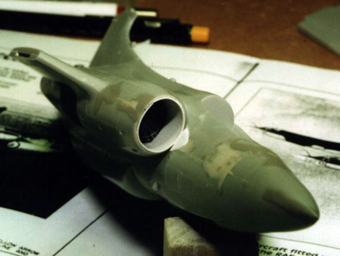
The Fuselage
The main part of the fuselage is split horizontally, only the nose
radome is a separate piece. The fuselage halves didn’t match as they
were warped differently, and some cuts had to be made to the fuselage
halves.
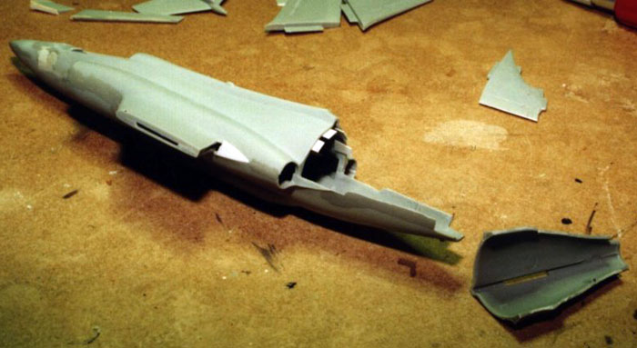
Backing plates for the photo etched engine fans were glued in the rear
of the air intakes before the halves were mated in a very painstaking
process.
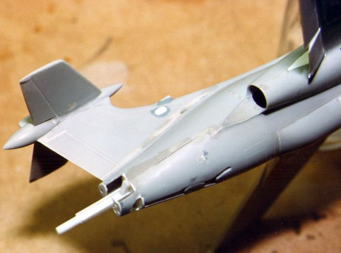
The fin was slightly corrected in the rear to get the profile right, the
rudder received some plastic to change the angle slightly. The small
blade antennas were exchanged to new better-looking ones and the cooling
air inlet at the base of the fin was reshaped to its correct form. The
fit between the fin and the fuselage is undefined and called for a few
dry fitting sessions.
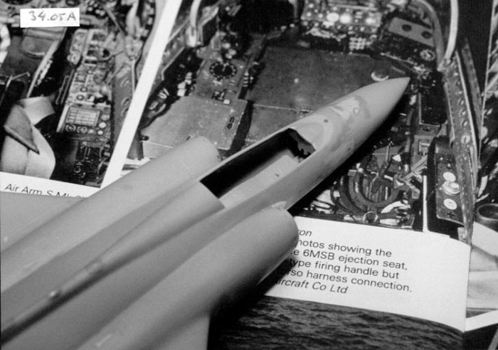
The radome is reasonably correct in profile with some work on the
fuselage front end. Some Milliput was still needed to blend the two
differently shaped objects after the radome had been glued to the
fuselage.
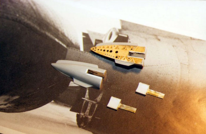
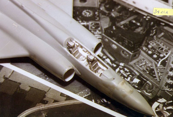
The intakes are not the kits best features! I cut a piece of thin
styrene sheet and inserted one in each intake to get a smooth inner
surface. It was not really difficult to do this and the seam of the
inner lining is in the top so it doesn’t show unless you pick up the
model. They were painted with Humbrol Metalcote Aluminum together as was
the photo etched turbine fan, which was polished and inserted through
the intake and glued to the backing plate. Finally I added the small
bump on the fuselage side in front of the intakes, made from plastic
card.
On the tail plane I tried to minimize the size of the front and rear
cones as they are way too large in the kit (I think there is a resin set
on the market now correcting this area).
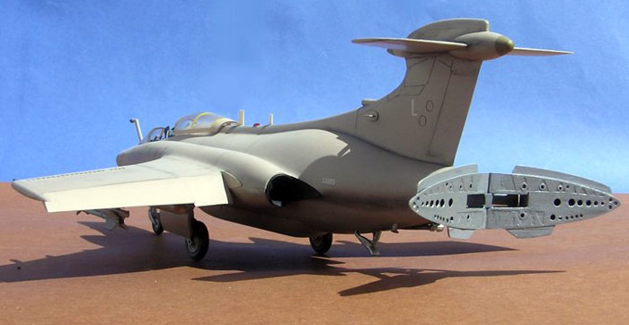
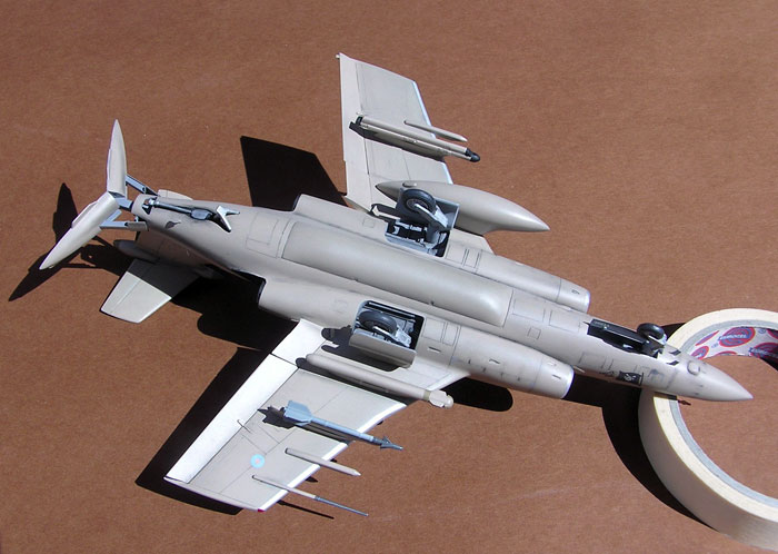
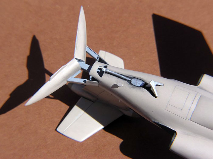
The prominent split-tail air brake was modeled open. The details of
this area were plain wrong in the kit, so I scratch built the inner
structure and hydraulics using mostly brass plate and sheet styrene,
completed with the Airwaves PE air brake interior.
Click the
thumbnails below to view larger images:
I had some pictures but not all information, as I became aware of when I
saw the Buccaneer live in the Fleet Air Arm Museum. In true British
spirit the air brake does not open as you would expect! From closed
position the two halves open simultaneously but nor symmetrically to the
fuselage center line; they go slightly to the left! I will not rebuild
the air brake on this model, but for sure do right the next time!
The ill-fitting front windshield was glued to the fuselage now with
epoxy glue, it’s lower edge faired in to blend with the fuselage. The
weak bond of the epoxy glue caused some problems as I managed to tear
off the windshield with the masking tape and had to repeat the whole
process.
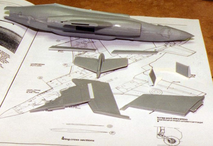
The Wings
I had decided to have the flaps in the dropped position, not realizing
how difficult this would be! The flap on the top wing half was removed
with a razor saw and on the bottom wing half I had to guess the size of
the flaps to be removed and because the flap is much thicker towards the
fuselage the geometry of the dropped flap was anything but easy to
reproduce. I had some photos of the flaps in my old Aeroguide book to
help me, but still the task was not an easy one! The result is
acceptable to me, judge for your self.
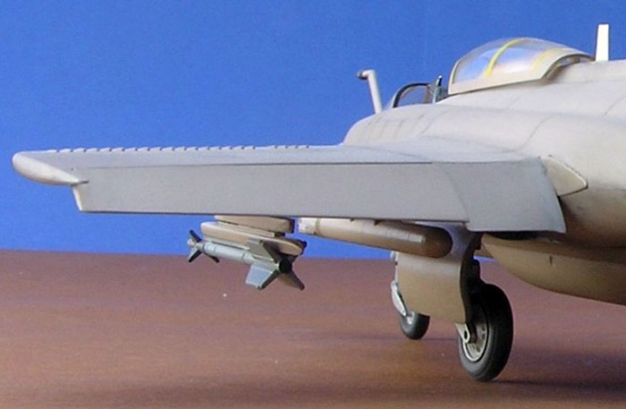
For this version the wing tips are short and excess plastic was cut off.
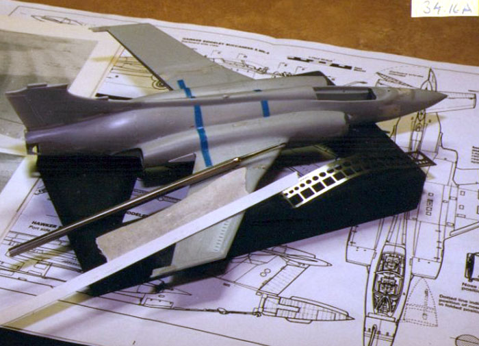
Assembly
When assembling the main airframe components - fuselage with wings
and stabilizers - I use a simple jig to ensure correct alignment. On a
hard surface, I fix the fuselage in an exactly upright position, mate
the wigs/stabilizers and then support them with a paint jar or other
suitable item with just the right size to ensure that all angles are
straight. I then let the model rest until the glue has cured. Adjusting
the jig can take some time, so I never use superglue for wings and
stabilizers but rather liquid poly with its comfortably long bonding
time. At this stage I also scribed the remaining panel lines.
Click the
thumbnails below to view larger images:
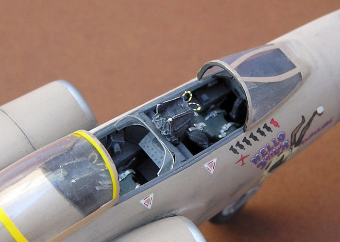
Cockpit
Only now my attention turned to the cockpit, realizing the Airwaves PE
set would not improve the cockpit much. But, in a model like this, the
cockpit interior can be built from the outside and this is what I would
do! My Dremel and knife was put to work and soon all traces of the old
cockpit were gone. Guided by photographs of the real thing, I furnished
the interior with styrene bits with the addition of a few Airwaves photo
etched panels.
The cockpit interior was painted dark gray and dry brushed.
One thing that should be noted with the Buccaneer is that the forward
seat is offset a little to the port side, while the rear seat is offset
to starboard. The seats themselves were white metal items from Aeroclub.
I completed them with seat belts added from strips of lead foil
(Bordeaux 1993) and Reheat buckles, and the Perspex shield for the rear
cockpit made from Lexan.
Click the
thumbnails below to view larger images:
Final Detailing
More antennas were added around the airframe, all scratch built items.
The camera blister under the nose was also scratch built. In-flight
refueling probe was another white metal part from Aeroclub.
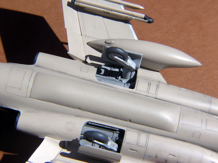
Now was the time for the final bits. Airfix chunky undercarriage parts
were replaced with white metal ones from Aeroclub. Wheel well interior
had to be scratch built and detailed with copper wire. The wheel bay
doors were replaced with new ones made from 0,2 mm brass plate.
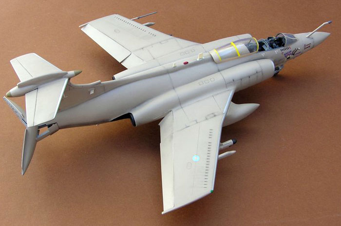
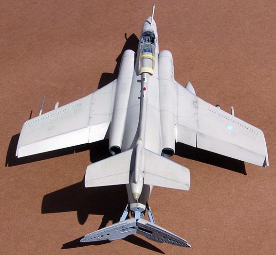
Under wing pylons were also scratch built. As for the stores, I have
chosen the following configuration often seen on Gulf War missions:
-
Station 1: AN/ALQ-101(V)-10 electronic countermeasures pod (Hasegawa)
-
Station 2: External fuel tank (kit item)
-
Station 3: AN/ASQ-153 Pave Spike laser designator (Scale cast)
-
Station 4: AIM-9L Sidewinder (Hasegawa)
Additionally, there are radar warning pods under each wing (scratch
built).
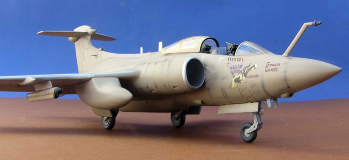
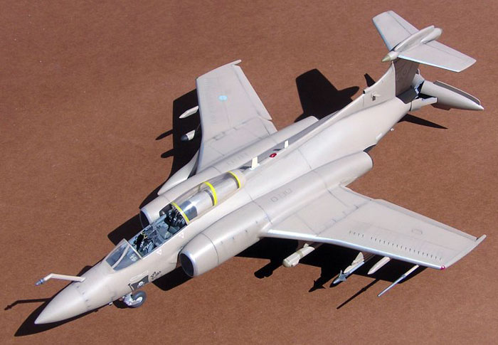
I finished my model as a Gulf War machine, RAF Buccaneer S.2B serial no.
XX885/L nicknamed Hello Sailor/Caroline. It also carried the name Famous
Grouse after a well-known Whisky brand, but personally I prefer malt
whisky. On the nose there is also a strike mission tally and a
silhouette of an An-12 Cub, one of two such aircraft that this Buccaneer
pointed with a Pave Spike and that were bombed by another Bucc during a
mission on Shayka Mayhar on February 27, 1991. The decals for this
machine came from Modeldecal.
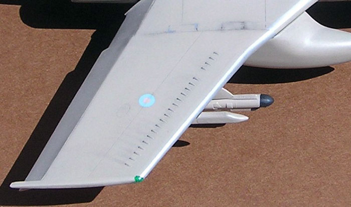
For the painting, I used Xtracolor enamels, X32 Desert Pink. Xtracolor
paints are glossy, so the decals were applied directly on the paint
coat, and then followed multiple layers of Future which were gently
sanded after each application. This procedure was repeated until no
trace of decal film edges could be seen.
Having the basic paint scheme ready, I applied a wash of black-brown oil
color mixed with white spirit, applied by brush over the entire model.
The wash added emphasis to panel lines and more variety to surface in
general. After some ten minutes the excess wash was wiped off with a
soft rag. This step allows precise control over the degree of weathering
left on the model - in this case, quite plenty of it!
The "dirt" was now sealed with a layer of Tamiya Clear acrylics mixed
with Tamiya Flat Base. Additional touches were made with dry pastel
chalk applied by soft brush in the areas that required more dirt;
particularly the dirt arcs forming behind the main wing vortex breakers
is typical.
A layer of Tamiya Clear and Flat Base sealed the pastels, and finally I
used the old piece of rag to gently rub the correct shine to some areas
of the airframe.
The canopy is in the far back position, and as it slides back along the
canopy sill it would have had its rear way up in the air on the model. I
fixed the canopy with the rear end down so it looks like the real
machine, but the line from the canopy sill to the canopy is strange to
say the least. I chose to use the kit canopy even though I bought the
Squadron replacement as it had some flaws.
In an old kit like this there are bound to be problems, but this is
probably the worst kit I have ever built for the last thirty years! I
could have done much more but you have to limit your effort in some way,
to me that’s around one hundred hours.
What an aircraft!
Click the
thumbnails below to view larger images:
 Home
| What's New |
Features |
Gallery |
Reviews |
Reference |
Forum |
Search
Home
| What's New |
Features |
Gallery |
Reviews |
Reference |
Forum |
Search