|
Azur's 1/32 scale
Dewoitine D.520
by
Ian Robertson
|
 |
|
Dewoitine D.520 |

Azur's
1/32 scale Dewoitine D.520 is available online from Squadron.com
The Dewoitine D.520 was the French Air Force’s best single engine
fighter at the outbreak of WWII. However, they were too few in number to
stem the onslaught of the advancing Luftwaffe. With the fall of France
in June 1940, many surviving D.520s ended up flying for the Vichy Air
Force in North Africa or for various other Axis air forces. Some D.520s
were pressed into service as trainers for the Luftwaffe.
With the liberation of France in 1944 a number French air units were
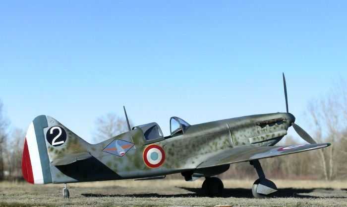
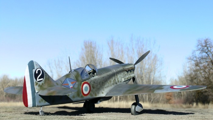
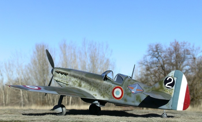
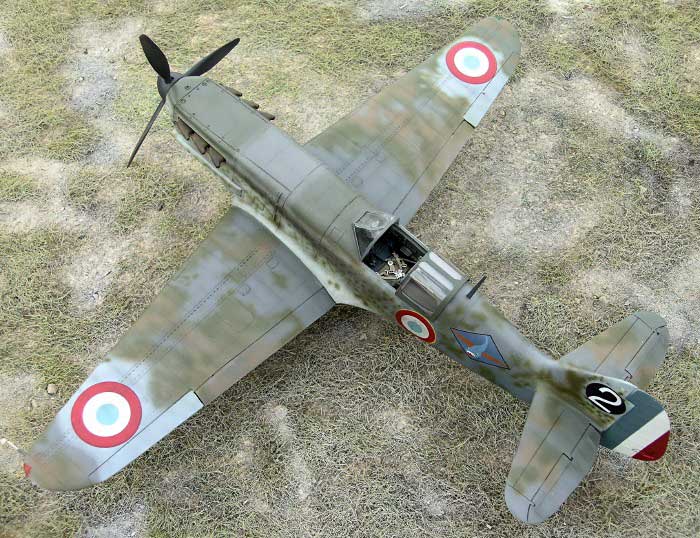
established using recaptured aircraft. My model depicts one such
aircraft, a recaptured Dewoitine D.520 from CGII/18 ‘Saintogne’ in
southeast France sometime between Dec 1944 and March 1945.
The Model
The model is Azur’s (initial release) 1/32 Dewoitine D.520 kit
enhanced with Contact Resine’s upgrade set and a Squadron vacuform
canopy. While not for beginners, the Azur kit is another example of the
steady improvements in quality being made by many short run
manufacturers. The kit is molded in grey styrene with finely engraved
panel lines and a single piece injection molded canopy. There are no
alignment pins and the horizontal tail surfaces fit with butt joints.
Fit is generally good, but there are a few hurdles to overcome during
construction.
The Contact Resine upgrade set is a highly detailed multimedia kit with
resin, photoetch, white metal, and vacuform parts (see Brett Green’s
review at
http://acc.kitreview.com/contactresined520reviewbg_1.htm ).
Although the upgrade set exceeds the price of the model kit and requires
some advanced modeling skills, for those inclined it greatly enhances
the detail and accuracy of the model. Either way, however, the completed
model will not be mistaken for anything other than a D.520.
Prior to construction I added rivets to my model using a “Rosie the
Riveter” hand tool. I then polished the model’s surfaces lightly with a
Micromesh sanding cloth to help tone down the visibility of the rivets.
I wanted the rivets to be barely noticeable rather than the first thing
to catch an observer’s eye.
Cockpit
Contact Resine’s cockpit is much more detailed that the kit cockpit,
although it is worth noting that the more recent “Hi-Tech” release of
the Azur D.520 kit includes a resin cockpit.
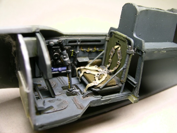
A detailed cockpit is particularly worthwhile if you plan on
displaying your model as I did with the canopy open.
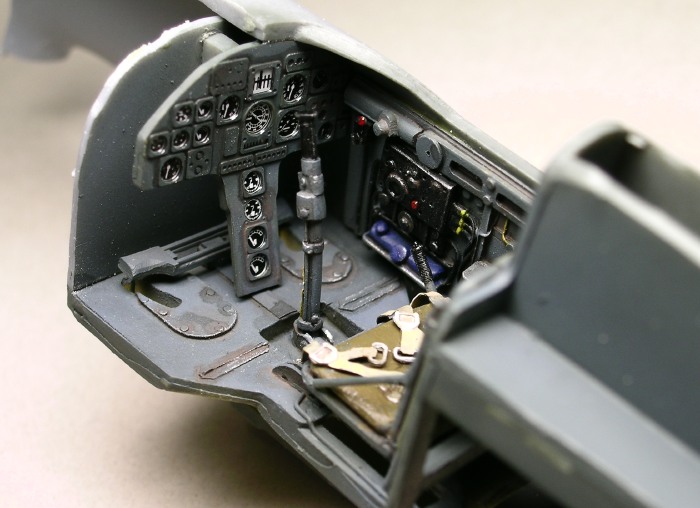
I painted the cockpit in Polly Scale’s French dark blue-grey darkened
with a touch of black. Washes and dry brushing were used to pick out the
details.
Wing Assembly
Once the cockpit was installed I glued the fuselage halves together,
attached the resin nose with CA glue (some sanding was needed to get a
smooth transition between the fuselage and new nose), and then proceeded
to the wing assembly. It was during the wing assembly stage I
encountered my first substantial difficulties with fit. Luckily, several
on-line reviews had alerted me to the problems in advance, so I
proceeded with caution to identify their causes. There were two main
issues to address: (1) the uneven joint where the underside of the wing
meets the rear fuselage, and (2) wing dihedral. I will deal with each in
turn.
A number of on-line reviewers have indicated that there is a large step
in the joint between the lower surface of the wing and the rear
fuselage. It turns out that this problem originates with the spars that
serve as backing for the flaps. Specifically, the spars are too deep and
thus cause the wing to be too thick at the trailing edge. Consequently,
when you attempt to line the upper wing sections to the fuselage wing
root, the lower surface of the wing sits well below the fuselage joint,
leaving a large step to contend with. The solution is to thin the spars
and test fit the wings before gluing them in place. Once you have the
proper wing thickness, the step between the wings and rear fuselage
disappears.
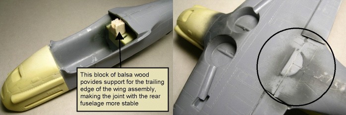
Before attaching the wings to the fuselage I glued a small block of
balsa wood to the underside of the cockpit assembly. This block provided
a solid support for the wing assembly, thereby allowing for a more solid
connection between the wing and rear fuselage.
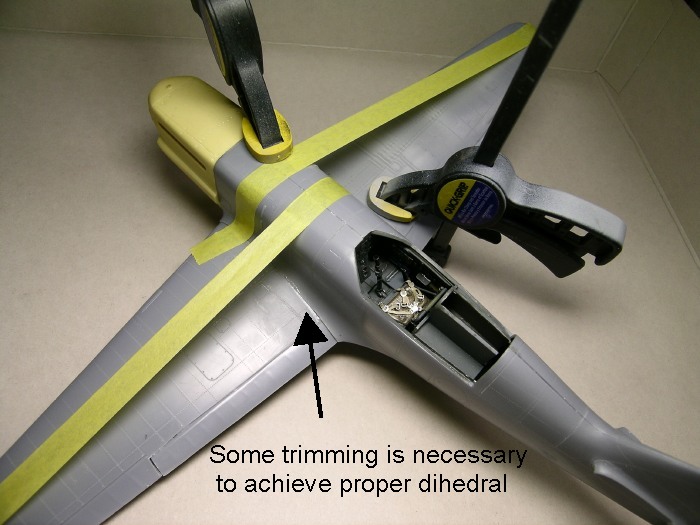
Unlike recent large scale releases from companies like Hasegawa, the
Azur kit lacks a wing spar that sets proper dihedral. In fact, test
fitting revealed that without modification there would actually be an
anhedral to the wings – not a good thing. But as with the previous
problem, the solution was simple. All that was needed was some trimming
of the inside edges of the upper wing sections, which then allowed the
wings to deflect upward into their proper dihedral. Tape was used to
hold the dihedral in place while the glue dried.
I opted to display my model with the flaps up, as this was more
common among D.520s on the ground. Some minor reshaping of the spars
discussed above was needed to accommodate the flaps.
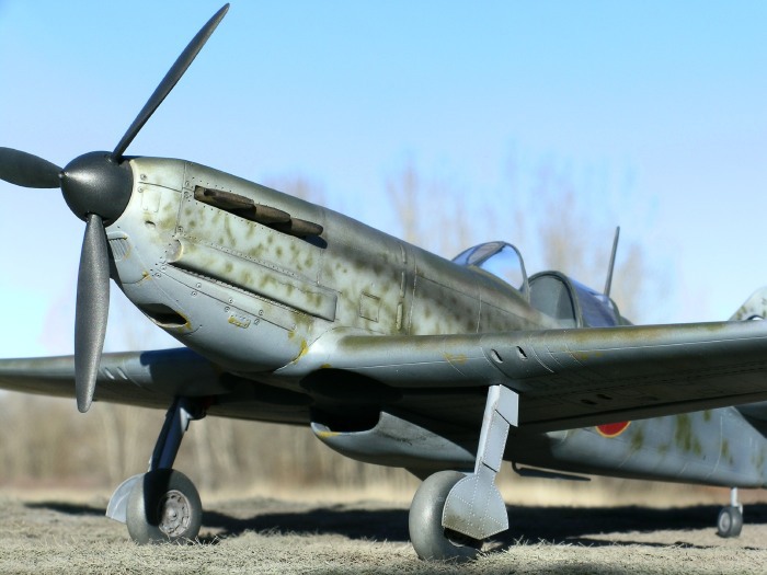
Engine Cooler Intake
The kits engine cooler is longer and less portly than the Contact
Resine replacement. After staring at numerous photos of restored D.520s
I decided that the resin replacement more accurately reflected the shape
of the actual engine cooler.
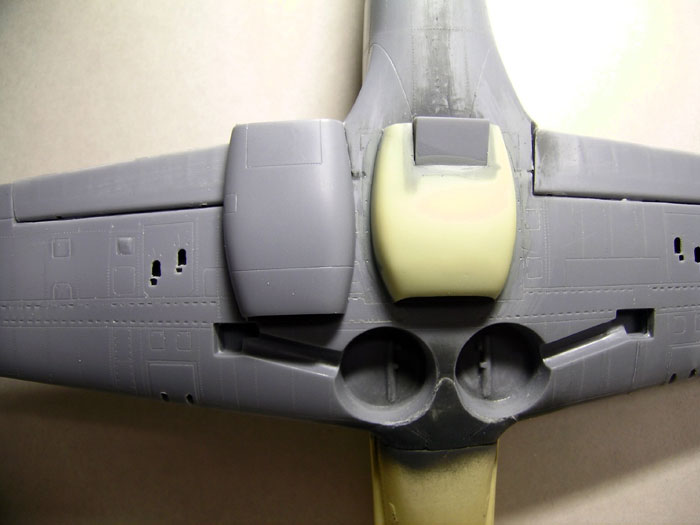
Note that in the photo above the resin part is positioned too far
back.
Canopy
Azur provides a single piece injection molded canopy with their kit.
However, I wanted to display the canopy open to expose the detailed
cockpit. I used a razor saw to cut free the front and rear sections of
the kit’s canopy, and then secured those pieces to the model, taking
care to fill any gaps or seams.
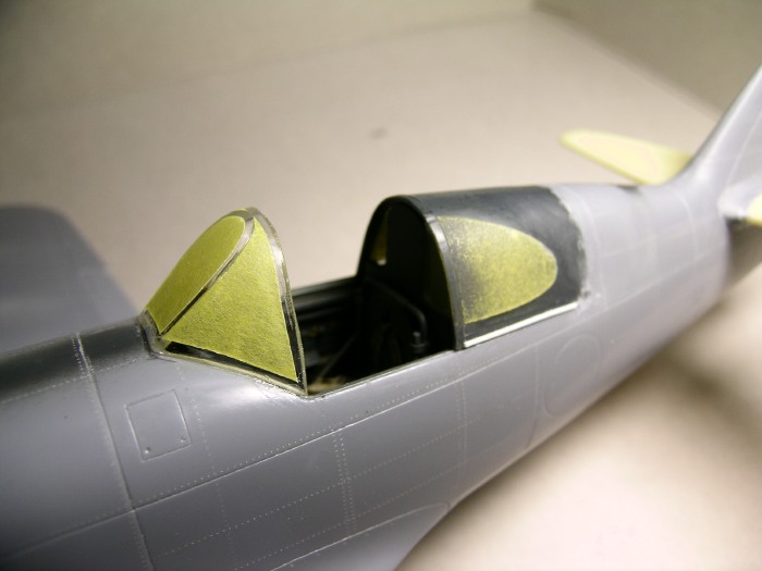
The center section of the canopy was a Squadron vacuform replacement.
Although a vacuform canopy was included with the Contact Resin set, the
quality of mine was not as good as the Squadron canopy.
Prop Blades
The kit’s propeller blades are substantially smaller than the Contact
Resine replacement blades (see photo).
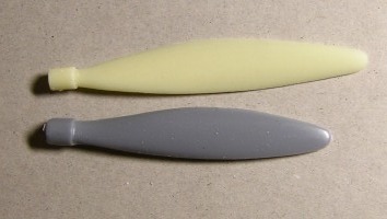
I used the replacement blades, but attached them to the kit’s spinner
assembly rather than the resin spinner (Actually, I broke all three
resin propeller blades at the base while trying to fit them into the
replacement resin spinner – enough was enough).
Paint Scheme
 I
chose this particular D.520 based on its challenging paint scheme and
interesting history. An artistic rendering of the aircraft is featured
on the back cover of Squadron’s “French Fighters of World War II In
Action”, and there are several in-flight photos of the aircraft in a
number of books (e.g., Mushroom Model Magazine’s “Dewoitine D.520” on
page 27). I
chose this particular D.520 based on its challenging paint scheme and
interesting history. An artistic rendering of the aircraft is featured
on the back cover of Squadron’s “French Fighters of World War II In
Action”, and there are several in-flight photos of the aircraft in a
number of books (e.g., Mushroom Model Magazine’s “Dewoitine D.520” on
page 27).
In planning the paint scheme I began with the premise that the
Germans would have repainted the aircraft to meet their regulations
before using it as a trainer. Indeed, numerous photos exist of D.520s in
German service repainted in RLM74/75/76, often with “fish style” spots
(likely RLM 74 or 75) on the sides. The undersides of these training
aircraft were painted yellow. Once the French recaptured the aircraft
they would have painted out all German markings with French colors and
perhaps applied some additional camouflage to prevent confusion or
enhance the camouflage effect.
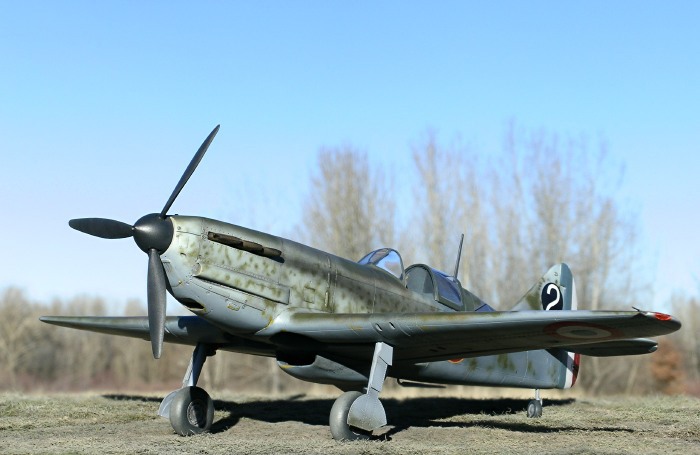
With this scenario in mind, I began by painting my model in a standard
German RLM74/75/76 scheme. Small mottles of RLM 74 were sprayed on the
fuselage sides to create the fish-style pattern seen in photos. I then
repainted the rear fuselage and tail in French dark blue-grey to conceal
the areas where German markings would have been. Mottles of French khaki
were added over the dark blue-grey, consistent with photos of the
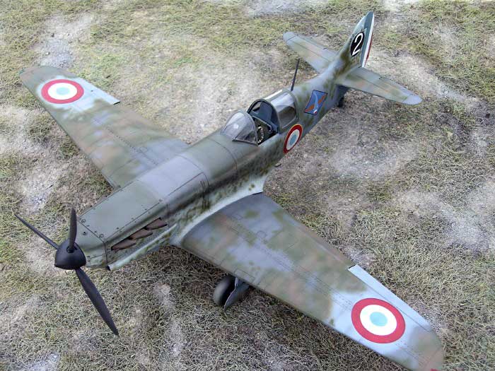
aircraft. The wings were treated to irregular patches of French khaki
and earth brown to help obscure the splinter scheme. Patches of French
light blue-grey were sprayed at the wingtips where the French roundels
would later be placed. I painted the undersides in French light
blue-grey. I then dry-brushed small amounts of yellow on some of the
leading edges on the undersides to represent areas where the yellow of
the previous paint scheme had been exposed.
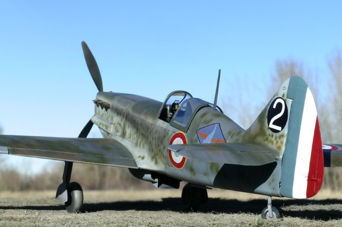
Lightly thinned black paint was sprayed to simulate exhaust stains.
Apart from these stains I did not weather the model much because the
recent repainting in French colors would have likely covered up faded or
worn areas of paint.
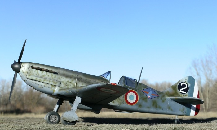
Decals
I used kit decals for the wing roundels and dry transfers from
Contact Resine for the fuselage roundels with yellow trim (note that the
“Hi-Tech” release of the Azur D.520 kit has this style of roundel). I
printed my own decals for the unit symbol and tail number using Testors
decal paper and an inkjet printer. The results were better than I had
expected.
The unit symbol decal I made was based loosely on a 1/32 dry transfer
produced by Contact Resine for a similar aircraft, “white 6”. I modified
the colors and dimensions of the symbol to match more closely what I
could discern from photos.
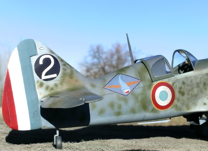
The number for the tail was created in Photoshop by scanning an
appropriately shaped “2” from a 1/48 decal sheet, rescaling it, changing
the color to white, and then placing it on a black circle. The decal was
printed onto clear decal paper and placed over a white disk painted on
the model.
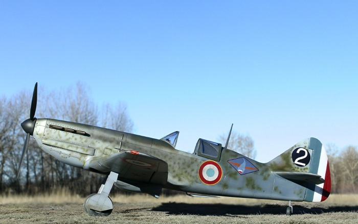
Images of the completed model were taken outdoors in natural light
with a Nikon Coolpix 5400 digital camera. The “unsharpen mask” tool of
Adobe Photoshop was used to restore some of the clarity and crispness
lost during image compression.
Click on the thumbnails
below to view larger images:
Model, Images and Text Copyright ©
2006 by Ian Robertson
Page Created 02 March, 2006
Last Updated 21 February, 2007
Back to HyperScale
Main Page
|
 Home
| What's New |
Features |
Gallery |
Reviews |
Reference |
Forum |
Search
Home
| What's New |
Features |
Gallery |
Reviews |
Reference |
Forum |
Search