|
Scratchbuilt
1/72 scale
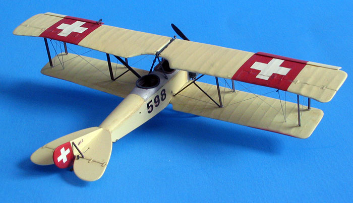
Haefeli DH-3
by Thomas
Muggli
|
 |
|
Haefeli DH-3 |

HyperScale is proudly supported by Squadron
Building a model from scratch, without the benefit of a kit, has
always been intriguing to me. I decided that scratchbuilding a WWI era
aircraft would be a good way to test my skills. I chose the Haefeli DH-3
as the subject of my project. The DH-3 would be a welcome addition to my
collection of Swiss Air Force 1/72 scale aircraft.
The Haefeli DH-3 entered service in 1917. Over 100 Haefeli DH-3s were
built and remained in service with the Swiss Air Force well into the
1930s. They were used for training, observation and liaison.
Before getting started
I realized early on that when building a model from scratch you
operate without the most important piece of reference material – a
plastic kit! The first step when starting a regular modeling project is
to open the box and examine the kit parts. When starting a
scratchbuilding project the first step is to determine how the parts and
subassemblies will be made. This is very important to avoid getting
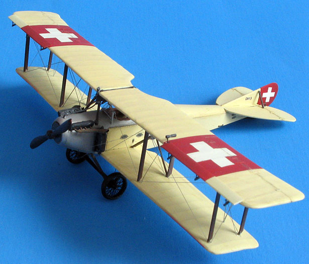
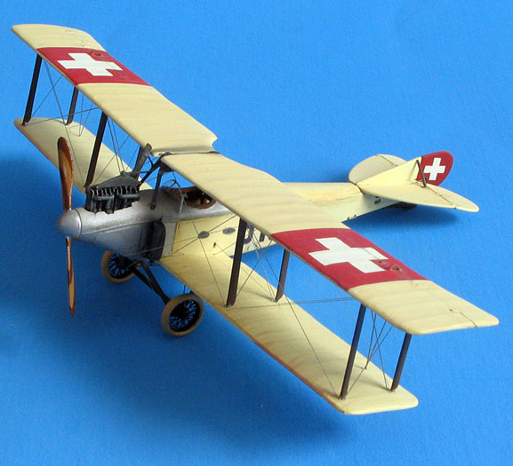
stuck in the middle of the project. I was planning to build two DH-3s,
one would be an early model with an Argus engine and one later model
featuring a Hispano-Suiza engine and Handley Page slats.
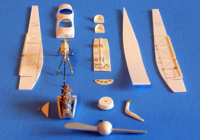
Once I had a good idea of how everything would come together, I gathered
the materials I would need: Plenty of sheet styrene of different
thickness, styrene rod and tube, brass rod, steel wire, a white metal
Argus engine from Aeroclub, spoked wheels from Tom’s Modelworks and
propellers from my spares box.
Wings
I started by cutting a 1mm (0.04”) styrene sheet so its width would
match the models wingspan. Next, I clamped a sheet of 150 grit sandpaper
to my workbench, and started sanding the edge of the sheet at an angle
of approximately 10 degrees. Once the edge was tapered to match the rear
portion of the wing profile, I cut a strip from the end of the sheet,
which I had just sanded. The width of the strip needs to be 2 mm less
than the wing chord. Holding the strip at an angle I sanded the freshly
cut edge of the strip to match the profile of the wing’s leading edge.
Using a no. 11 blade in my Xacto knife and a sanding stick I shaped the
outline of the wing. The whole process was repeated for the upper and
lower wings.
To achieve the curved profile typical of WWI airfoils, I heated the
wings slightly under my workbench lamp and bent them over a broomstick.
Heating and bending needed to be repeated a number of times until I was
satisfied with the curvature of the wings while making sure they
remained straight and didn’t get warped in the process.
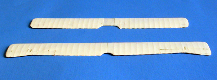
The wing cores were laminated with 0.125 mm (0.005”) sheet styrene.
Again, I cut a sheet to the width of the wingspan and four times the
length of the wing chord. The location of the ribs was marked at each
end of the sheet. The marks were then connected with a regular ballpoint
pen and a ruler. This was done on a soft cutting surface using ample
pressure so the sheet would be scored enough that lines would be visible
on the back of the sheet. The sheet’s backside now simulated the wings’
surfaces and its rib structure. The sheet was then cut into four strips,
which need to be as wide as the full wing chord. Finally, they were cut
in half so I could glue them separately to each wing half.
I glued the edge of each strip flush with the leading edge of the wing
core using a small amount of liquid cement. Once the liquid cement had
dried, a liberal amount of slow drying superglue was applied to the
trailing edges and spread with a putty knife between the wing core and
the partially glued strips. The strips were carefully pressed down
making sure they were completely attached to the wing core and there
were no bumps or kinks in the wing’s surface. On the trailing edges the
strips would stick out 2mm from the wing core. In this area the strips
on the top and bottom of each wing would be glued directly to each
other. This created a thin, realistic looking trailing edge. After the
glue was dry, all the edges of the wings were lightly sanded to clean up
any steps and gaps between the strips and the wing core. The wings were
now complete. I put them to the side until I was ready to mate them to
the fuselage.
Fuselage
I started by cutting the fuselage sides and bottom from 0.04” (1mm)
sheet styrene using my three-view drawings as a guide. I also cut a
bulkhead, which would be installed behind the cockpit.
Because I did not have any reference photos of the DH-3’s cockpit, I
built a generic WWI era cockpit for my models. Seats, control columns,
rudder bars, instrument panels and internal framework were made from
strip and sheet styrene. I added throttles from a photo-etched detail
set and seatbelts made from aluminum foil. Once the cockpit components
were painted and installed I joined the fuselage sides, bottom as well
as the bulkhead with superglue.
The Argus variant received an Aeroclub white metal engine. The engine
needed to be trimmed a bit on its sides and bottom to fit the fuselage
contours. I built a cradle for the engine from styrene strips. The
cradle would help to fit the engine snug between the fuselage halves and
bottom. A similar cradle was fashioned for the forward fuselage of the
Hispano-Suiza variant, even though it was only going to serve as a base
for the cylinder rows, which are the only visible part of the engine.
The cradles also provided a stable structure for the forward fuselages,
which required quite a bit of sanding and shaping.
The components for the upper fuselage areas covering the cockpit and
engines were made from 0.02” (0.5 mm) sheet styrene stretch formed over
masters shaped from laminated styrene strips. The upper rear fuselage,
the area between the cockpit and the engine, as well as the fuselage tip
were fashioned from laminated sheet styrene and shaped with a sanding
stick and files. I glued all the fuselage components in place with
superglue.
What was still missing were surface details. I made various panels from
0.005” (0.125 mm) sheet styrene and glued them with liquid cement. To
represent sewn seams I scribed a tight diagonal pattern on a portion of
0.005” (0.125 mm) styrene sheet. Then I cut thin strips and attached
them with liquid cement. The tail surfaces were cut from styrene sheet,
sanded to shape and installed with superglue.
Struts
I came up with my own method to make sturdy struts: I used 0.02 “
(0.5 mm) steel wire. You can’t get much sturdier than that. The wire was
cut into pieces 2 mm over the length of the struts. To give the struts
the correct appearance I mated the wire pieces with tapered plastic
strips. To produce the tapered plastic strips I sharpened the edge of a
0.02” (0.5 mm) styrene sheet by sanding each side at an approximate ten
degree angle on a piece of sandpaper fastened to my work surface. I cut
2 mm wide strip from the sharpened edge. The strips were then cut into
piece the exact length of each strut. The process was repeated a number
of time until there were enough strips for the 16 struts needed for both
aircraft.
To glue the wire pieces and plastic strips, I placed them on
double-sided tape to hold them in place. The plastic strips need to be
centered so there will be an extra 1mm of wire at each end of the strut
to fit into holes which would be drilled into the wings. I applied
superglue to the seam between the wire and plastic strip and let it dry
for a few minutes. While the pieces were still on the tape, I sanded the
seam. The pieces were then turned over, and the gluing of the seam
repeated, so both sides of the strut would be smooth.
I used “Strutz” brass stock for the landing gear struts. The wheels were
made from Tom’s Modelworks photoetched set, while the tires were
fashioned from laminated pieces of styrene tubing. Styrene strips and
copper wire became the radiators and tail skid. Finally, I raided my
spares box for propellers and shaped the spinner for the Argus DH-3 from
laminated styrene pieces.
Final Assembly
With all the subassemblies complete, it was time to put them
together. I drilled holes in the lower fuselage to accept pegs made from
copper rod. Next, I drilled holes in the lower wing roots so they could
be mated with the pegs installed in the fuselage. I broke out the
superglue and attached the lower wings to the fuselage. Proper alignment
is of utmost importance here.
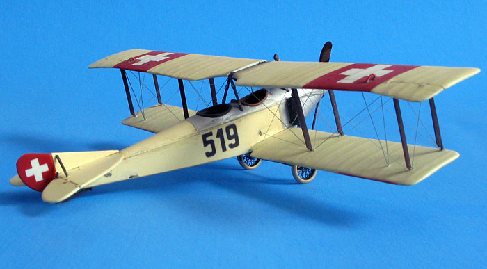
At this point, I painted the models with acrylics. My doped linen shade
is a 50/50 mix of tan and white with a drop of yellow. The bare metal
sections were airbrushed aluminum straight from the bottle, while the
struts were painted dark brown. I masked and airbrushed the national
insignias. The registration numbers were created on my computer and
printed on clear decal paper.
When painting was completed, the cabane strut/fuel tank assembly was
fitted into holes drilled in the upper fuselage. Next, I drilled holes
in the upper wing roots to accept Copper rod pegs, which had been
incorporated in the cabane strut/fuel tank assembly when it was
originally constructed. I glued the wing struts into holes drilled in
the upper wings paying careful attention to proper angles and alignment.
I then test-fitted the upper wings. In the process I marked the
locations of the wing struts on the lower wing with a pencil. After I
drilled holes for the wing struts in the lower wings, the upper wings
were again dry-fitted and finally glued in place with superglue.
I prefer to use silver or gray stretched sprue as a rigging material. It
is flexible and easy to work with, and it doesn’t need to be painted.
The biggest challenge is to install the rigging taut. The method I chose
was to drill small holes in the wings as close to the wing struts as
possible where the attachment points of the rigging would be. The holes
were drilled before the struts and wings were installed. When everything
was in place, the rigging was sewn through these holes and secured at
the attachment points with small amounts of superglue. Rigging this way
was fairly fast and easy. The downside of this method is that the excess
rigging needs to be removed and holes filled on the upper and lower
surfaces of the wings where they exit. After spending considerable time
touching up the paint by hand, and with my airbrush, I applied a final
coat of clear flat and added the last few detail parts. My two DH-3s
were now finally finished!
The roughly 130 hours I spent on this project were a bit more than I
had anticipated. Nevertheless, building my Haefelis was a very exiting
and rewarding experience.
Click on the thumbnails
below to view larger images:
Model, Images and Text Copyright © 2006
by Thomas Muggli
Page Created 13 September, 2006
Last Updated
21 February, 2007
Back to
HyperScale Main Page
|
 Home
| What's New |
Features |
Gallery |
Reviews |
Reference |
Forum |
Search
Home
| What's New |
Features |
Gallery |
Reviews |
Reference |
Forum |
Search