|
Dijun's 1/72
scale
EKW C-36
by Thomas
Muggli
|
 |
|
EKW C-36 |

HyperScale is proudly supported by Squadron
For some time, I wanted a C-36 for my collection of Swiss Air Force
aircraft. I had long considered scratchbuilding a C-36 when I came
across the resin kits made by the French company Dijun. They offered
resin kits of several versions of the C-36. I shelled out a small
fortune for kits of the original C-3603 combat aircraft, the advanced
C-3604 and the C-3605 target tug. I decided to get started with the
C-3603 and the C-3605. The C-3604 wound up on the “to be built at a
later date” pile, since I don’t have much reference material about this
type.
Background
The C-36 was designed in 1942 by the Swiss Federal Constructions
Works (Eidgenoessische Konstruktionswerkstaette, or EKW for short) in
Thun, Switzerland as a multi-purpose fighter-bomber. It serves as an
example of longevity. Replaced as a combat aircraft by jets shortly
after WWII, it remained in service as a trainer and target tug for many
more years. In the late 1960s the remaining C-36’s ancient Hispano-Suiza
engines had become a maintenance nightmare. It was time for the Swiss
Air Force to look for a new target tug aircraft.
After careful evaluation the choice was made: the C-36. 24 of the old
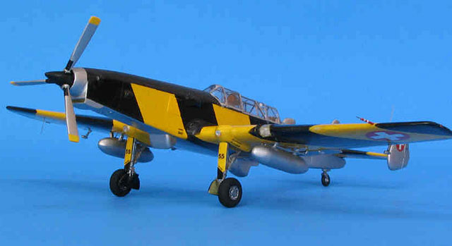
C-3603 airframes were retrofitted with Lycoming turboprops. The result
was the C-3605, a sleek looking aircraft, which reminds me of a
pocket-sized Lockheed Constellation. The 45-year service history of the
C-36 finally ended in 1987 when the last C-3605 target tugs were
retired.
The Kits
I realized that I would be in for a challenge as soon as I received
the kits in the mail. The parts come in a plastic bag. There is no box,
instructions or decals provided. The only “instructions” are a
three-view drawing and a photocopied picture of the aircraft.
Thankfully, I had a number of good photos from magazines and some I had
taken at the Swiss Air Force Museum, in Dubendorf, Switzerland, of the
real aircraft. If I had just used the information provided with the
kits, it would have been impossible to complete the project. The wings
and fuselage were loose in the bag, while the smaller parts were molded
into a thin resin sheet. There were no pour stubs. It did not take me
long to notice the most serious problem: The
C-3605 kit contained two left fuselage halves, but was missing the right
half! Normally, I would have returned the faulty kit. But since I had
ordered the kits from overseas and wanted to get the project underway, I
decided to scratchbuild the right fuselage half instead. Further
examination also revealed that the C-3603 was missing the tip of the
fuselage.
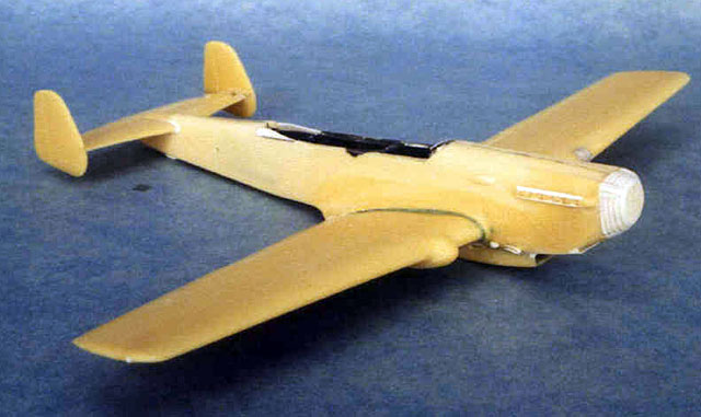
The first step of the construction was to replace the missing left
fuselage half of the C-3605. Other than the rounded top, the cross
section of the C-36’s fuselage is square. I built the square fuselage
portion first. Using the right fuselage half as a guide, I cut a new
fuselage side and bottom for the left side from sheet styrene. I also
made four bulkheads, which where glued evenly spaced to the front and
rear portions of the intact right fuselage half. For added strength I
also made two horizontal bulkheads and installed them to the upper
portion of the right fuselage half, between the vertical bulkheads
already in place.
The cockpit interior was next. I fashioned internal bracing from strip
styrene and also added thin copper wiring and electrical boxes made from
stryrene scraps to the cockpit walls. At the same time, I also glued the
cockpit floor, instrument panel, throttle and control columns to the
cockpit assembly. I used the seats provided in the kit, but installed
them after the model was painted. The cockpit was painted dark grey. I
also applied a wash of thinned, black acrylic paint and dry brushed some
aluminum to accentuate the various details. The cockpit details were
built up and painted the same way on the intact C-3603 model.
The next order of business was to join the fuselage halves. On the
C-3603 this was the standard procedure even though there were no
locating tabs. The fit was fairly good. At this point, I also added a
new fuselage tip made from laminated sheet styrene. The seams were
filled with superglue and sanded smooth. On the C-3605 on the other
hand, the operation was a bit more complicated. I sawed the turbine
intake portion off the right resin fuselage half. Then, I glued the new
left fuselage side and bottom to the bulkheads and let them dry
thoroughly. Next, I laminated several strips of 1mm-styrene strips and
glued them to the top of the left fuselage parts in front, and behind
the cockpit. Using a coarse sanding stick I shaped the laminated styrene
pieces to match the rounded top of the intact right fuselage half. I
closed the tip of the fuselage with a piece of 1mm sheet styrene shaped
to match the fuselage contour. Any seams and holes were filled with
superglue and sanded smooth. Panel lines on the new left fuselage half
were scribed to match the right half. I made a new circular turbine
intake for the tip of the fuselage from a section of a wing tank from my
spares box.
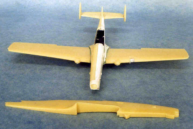
The wings were a pleasant surprise. They were molded in one piece and to
my delight there was no warpage, sinkholes or air bubbles. The only
items missing from the wings were the landing lights. I cut gaps into
the wing’s leading edges. Next, I glued pieces of chrome bare metal foil
into the gaps and added a piece of clear stretched sprue to each gap, to
simulate the light bulb. Finally, I fashioned the lenses from pieces of
stretch formed clear acetate and installed them with superglue. After
only a few passes with a sanding stick around the edges the wings were
ready for installation. Again, on the C-3603 this was not very
difficult. Only a few gaps appeared which were easily filled with
styrene strips and superglue.
However, due to the fuselage surgery, the wing installation on the
C-3605 was a bit more difficult. Careful test fitting was required
before the wing could be glued in place with liberal amounts of
superglue. Since the fairing between the wing and fuselage is molded as
part of the fuselage half, it needed to be replaced on the left side. I
glued several styrene strips to the wing/fuselage joint and gave them
the proper shape with a coarse round file and sandpaper. After carefully
checking that the new fairings on both sides matched, I filled some
holes and gaps with superglue and smoothed the seams using various grits
of sandpaper. The kit parts for the tail are not great, but they were
good enough for my taste. To strenghten the joints between the
horizontal and vertical tail surfaces, I drilled holes to accept steel
wire plugs. I glued the tail assemblies in place with superglue paying
careful attention to proper alignment.
The Canopies
My Dijun kits came with two canopies each. After literally spending
hours nipping, sanding and test-fitting, I had two canopies that would
fit my models halfway decently. Notably, there were no spare canopies
left when I was done. The windshield supplied in the kit is not correct
for a wartime C-3603. I stretchformed a new windshield from sheet
acetate. This did not create any additional fit problems since I
intended to pose the canopy of the C-3603 in the open position. I gave
all the canopy parts a bath in Future floor polish and let the dry
thoroughly.
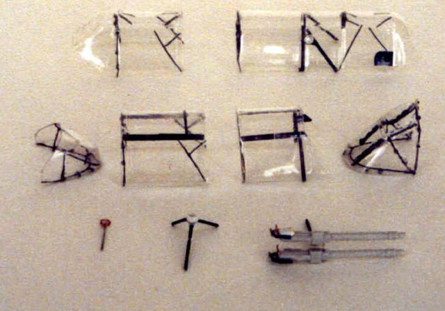
Real C-36s have a unique canopy construction. The plexiglas canopy is
mounted on a steel tube frame. This framework is quite noticeable, but
would be a challenge to create on a small scale model. Nevertheless, I
felt that this was an important characteristic of these aircraft and
should be represented on my models. So I went to work with fine copper
wire, stretched sprue and superglue to build the parts of the framework
that are visible on my reference photos. After painting them with the
interior color, I installed the various portions of the framework to the
inside of the canopies with tiny amounts of superglue. This was quite
delicate and time-consuming work but looking at the finished models I am
happy that I made the effort. I left the installation of the canopies
until the very end of the project after painting and decaling were
completed. For the external canopy frames I used clear decal film which
I first airbrushed with the interior color then the external color and
the same final clear coat I used on the model. The decal film was then
cut in thin stripes and applied to the canopies after they were
installed.
More Details
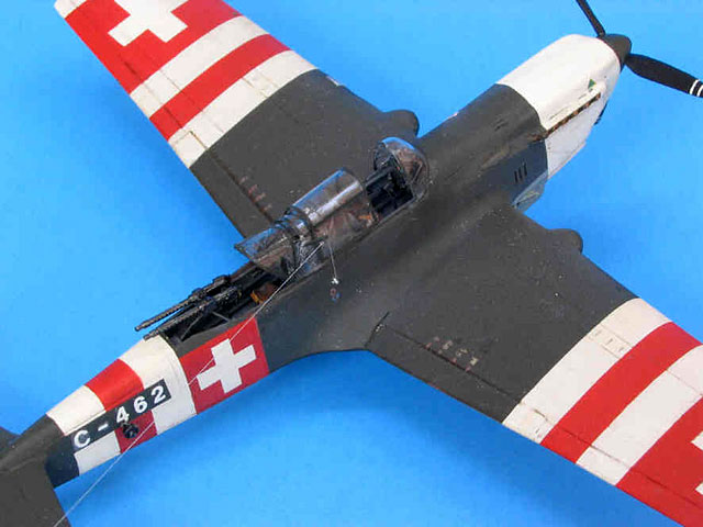
A number of detail parts on the underside of the C-3605 needed to be
scratchbuilt. I fashioned an air intake under the nose, the turbine
exhaust as well as the box containing the target reeling mechanism from
sheet styrene and scraps. The twin machine guns for the C-3603 came from
my spares box. The stand for the gun was made from steel wire. I also
detailed the gun with styrene scraps, copper wire and bits of brass left
over from a photoetched detail set.
I was fortunate enough that none of the landing gear legs, or propeller
blades, broke while being removed from their resin sheet backing, or
during the extensive cleanup which was necessary for these parts. The
landing gear legs, which would be bearing the weight of the model,
seemed particularly fragile. I could have made new ones from wire but
instead decided to cover the resin parts with a coat of superglue to
give them added strength. The landing gear actuator arms were missing
from the kits. I scratchbuilt them from bits of styrene strip. I used
the kit-supplied wheels for the C-3605. The wheels provided in the
C-3603 kit are incorrect, so I raided my spares box for a more accurate
set. I made the wheel covers from thin sheet styrene stretch-formed over
the upper portion of a kit-supplied wheel mounted on a wood dowel.
The kit-supplied tail wheels were too small for my taste. Once again I
reached for my spares box to find better-looking replacements. The
landing gear doors provided in the kits were not completely convincing,
but I decided to use them anyway. A number of additional details such as
aileron counterweights, pitot tubes were made from styrene scraps and
installed after the models were painted.
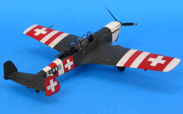
I painted my C-3603 in “Neutrality” markings. They were applied to
all Swiss aircraft between September 1944 and the end of the war.
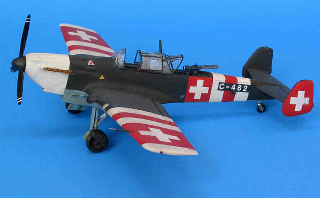
All markings with the exception of the registration numbers, which
are dry transfer decals, were airbrushed. I used acrylic paints from
Tamiya and Model Master.
 First,
I airbrushed flat white over most of the model, which also helped
identify some blemishes, which needed to be eliminated. The areas, which
were to remain white were masked off, then I airbrushed flat red. After
masking the red areas I airbrushed light blue gray (similar to Hellblau
RLM 65) for the undersides and masked once more before finishing the First,
I airbrushed flat white over most of the model, which also helped
identify some blemishes, which needed to be eliminated. The areas, which
were to remain white were masked off, then I airbrushed flat red. After
masking the red areas I airbrushed light blue gray (similar to Hellblau
RLM 65) for the undersides and masked once more before finishing the
upper surfaces with dark green (similar to Schwarzgrun RLM 71). For
weathering I applied a light sludge wash and airbrushed exhaust stains,
then applied a final coat of clear flat.
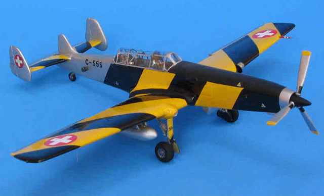
The C-3605 received the high visibility lemon yellow and black paint
scheme, which was applied to all aircraft during their whole careers.
Again, I used acrylic colors. For the bare metal areas, I airbrushed
Testor non-buffable aluminum. The decals for the national insignias came
from a Shadow decal sheet while dry transfer decals were used for the
registration numbers. I also made some small maintenance stencils on my
computer and printed them on clear decal sheet on my inkjet printer. My
spares box was the source of some other small markings. A final coat of
Future floor polish gave the model a nice sheen.
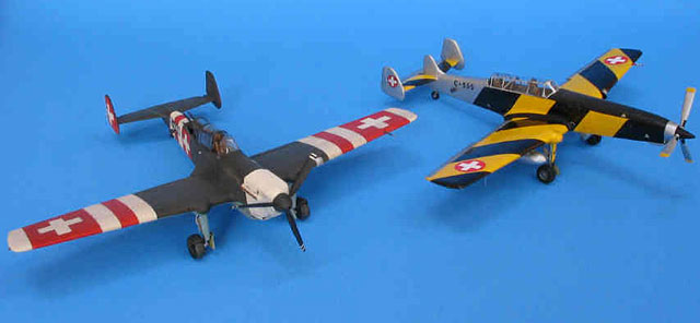
My two C-36s were my first resin project. It was a bit tougher than I
expected, but it showed that with patience and bit of elbow grease even
challenging resin kits can be made into quite presentable models. I am
positively ready for more resin!
Click the thumbnails below to view larger images:
Model, Images and Text Copyright © 2005
by Thomas Muggli
Page Created 11 November, 2005
Last Updated
10 November, 2005
Back to
HyperScale Main Page
|
 Home
| What's New |
Features |
Gallery |
Reviews |
Reference |
Forum |
Search
Home
| What's New |
Features |
Gallery |
Reviews |
Reference |
Forum |
Search