|
Building Revell's new
1/48 scale
F/A-18E Super
Hornet
Part Two
by
John Chung

Revell's 1/48 scale F/A-18E Super Hornet is available online
from Squadron
For more information about the new
1/48 scale Revell
F/A-18E Super Hornet, please visit my
in-box review here on Hyperscale.
Wings
The kit inner wings were molded integral to the fuselage halves with
the outer wing split roughly where the wing fold is. While this
eliminates problematic wing-fuselage joints, test fitting reveals
careful alignments of outer wing sections would still be necessary (see
title image)
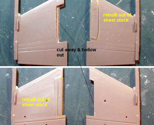
While the wing breaks roughly at the wing fold, it really isn’t possible
to pose them folded without some work still. To start, a section of the
outer wing will need careful removal and the displaced area rebuilt;
namely the upper panel that folds up and a small strip on the bottom.
The wing fold mechanism consisted of just strip styrene of styrene
wrapped around a styrene rod.
Click the thumbnails below
to view larger images:
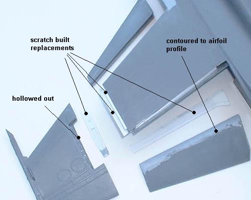
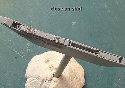
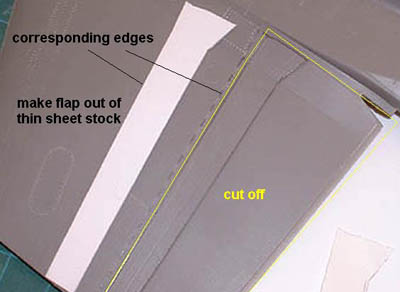
As the F/A-18 Hornets typically park with fully deployed trailing edge
flaps due to bleeding of hydraulic pressure upon shutdown, I’ve elected
to drop them on the model. The Hornets are equipped with single-slotted
Fowler flap which is a bit more involved to modify. The flaps were first
cut from the wings; the top piece removed along with the panel just fore
of it, the latter of which was replaced with a scratch built item. The
removed flap was then filled and profiled to a proper airfoil.
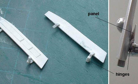
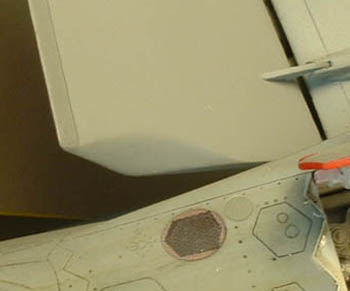
The flap hinges were modified corresponding to the new flap position,
and an actuating rod inboard the flap was built to support the assembly.
Overall alignment was done at this point to ensure symmetry between the
two wings. Note that there should be a very fine slot between the flap
and the wing as featured on Fowler flaps.
Click the thumbnails below
to view larger images:
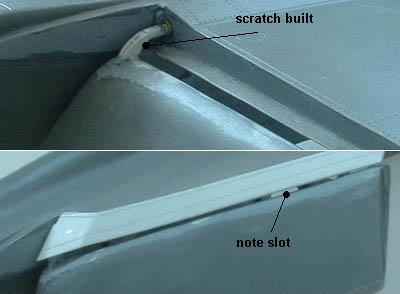
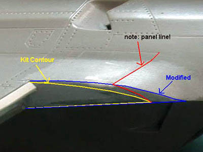
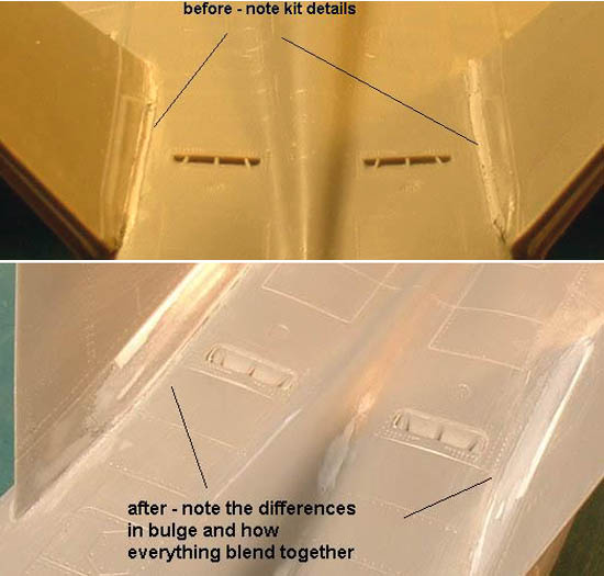
A small cut out should be made on the aft inboard corner to clear the
fuselage missile station. The fuselage corresponding to the flap was
also filled in and built up with appropriate surface details. Similarly,
the fuselage contours adjacent to the leading edge flap was slightly off
and was built up and the correct surface detail rescribed.
Click the thumbnails below
to view larger images:
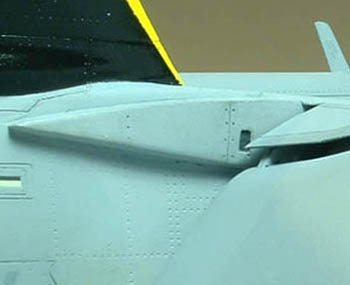
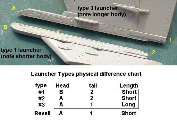
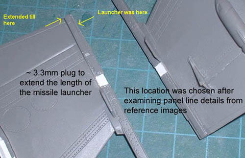
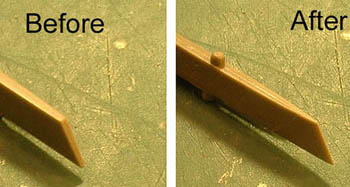
Lastly, the wingtip launchers were slightly modified for a more
accurate representation. The Super Hornet uses three different types of
wingtip launchers distinguishable by their respective physical
differences. By observation, it seemed Revell had crossed between the
details so a ~3.3mm insert was added just aft of the wingtip formation
lights to alleviate this issue.
Click the thumbnails below
to view larger images:
Empennage
The horizontal stabilizers were attached via a carry-through member
inserted into the aft fuselage. This design allowed very rigid and
positive attachments than most other kits concerning stabilator.
However, make certain you do NOT try and attach these before they’re on
permanently, otherwise you’ll mostly likely break something trying to
remove it . . . uh, like I did.
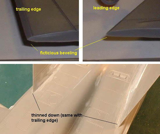
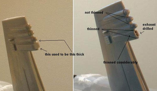
The vertical stabs were an enigma. They were molded with strange, thick
beveled leading and trailing edges that needed removal and lost details
replaced. More annoying was the stab base reinforcement bulge, which was
wrong and needed quite a bit of re-profiling on both inside and outside.
The general fuselage contour in this area was also off enough that the
removed rudder would not deflect due to interferences with the fuselage.
Consequently, the vertical stab base, rudder and fuselage contours were
also reshaped. Lastly, the upper trailing edges exhaust ports were
thinned down and drilled out.
Click the thumbnails below
to view larger images:
Aft Fuselage
The Revell exhausts were too small and short internally, ending at
where the finger braces meet the fuselage, a by-product of the
horizontal stab carry-thru member. I elected to resort to heat-and-smash
covers once again as a fix would have been quite involved. Also note
that the exhaust feathers should have a slight clockwise-twist while
Revell had them straight. As well, the finger braces should follow the
fuselage contours while Revell had them along the feathers.
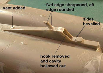
The arresting hook and faring were molded in a single piece, so they
were removed and separately improved upon. The hook was refined both at
the base and the tip, and the faring also received minor detailing.
Click the thumbnails below
to view larger images:
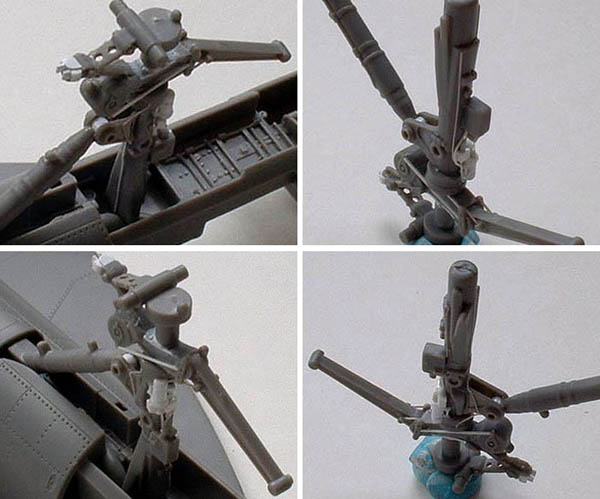
Landing Gear
The kit landing gears were generally well done for a
single-piece affair, but lacked the details and finesse of a multi-piece
assembly.
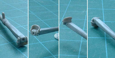
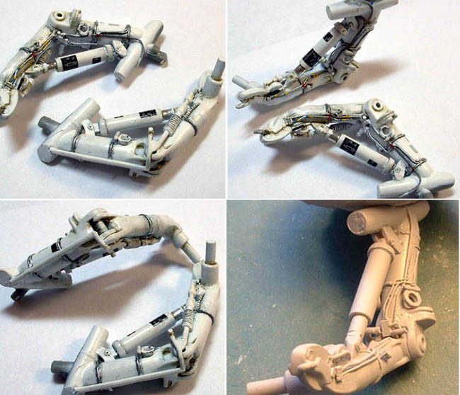
The nose gear strut launch bar linkages were removed and rebuilt, along
with the retraction/main strut elbow which was hollowed out. Holes in
the shock scissors were detailed out and the oleo shortened by a bit to
reduce the nose-high phenomenon. Further detailing included misc. wires
and bottles from styrene rods and sprue. Improving the main gear struts
was a bit more involved, the chief of which was the drilling out and
modifying the solid knee joint. The shock struts were replaced with
brass tubing as the kit items were poorly molded on a diagonal.
Additional hydraulic wires, tie-downs, and other items complete the
detailing.
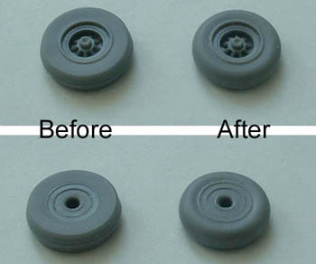
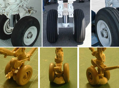
Attention was given to the nose wheels, which were a little too squared
and the thread details piled up like mini stepped pyramids. The threads
were sanded down and the tires rounded off at the corners and around the
rims. Thread details were not replaced because, well, I can’t scribe
threads if my life depended on it.
Click the thumbnails below
to view larger images:
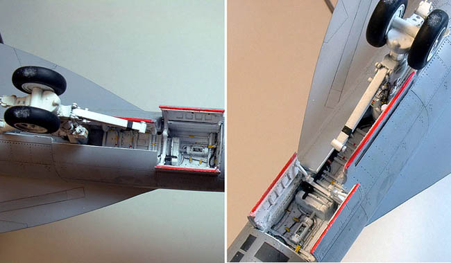
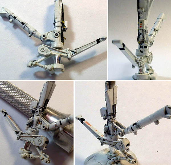
The struts were painted with Tamiya gloss white and weathered with
artist’s oil paints prior to flat coating. The oleos were covered with
bare metal foil, and the various wires and pipes painted appropriately.
Decals were a mix of kit supplied placards and scrap bin scavenged.
The gear bays didn’t come out as nice as I had hoped, given the
relatively soft and overly busy molded-on details. Do take note that the
red trim on the gear doors have specific patterns, especially the MLG
doors.
Click the thumbnails below
to view larger images:
Stuff That Hangs
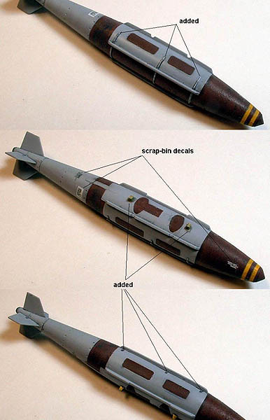
The GBU-16 and JDAM were from Hasegawa’s weapon set. The USN
anti-fire coating was reproduced by scrubbing with toothbrush over the
plastic surface softened with liquid cement, being careful to achieve a
very subtle effect. The GBU-16 had the forward and aft (retracted) fins
replaced and the seeker head hollowed and lowered. Both bombs were also
detailed with a few other paraphernalia. Decals were once again a
combination of weapon set’s and those from the scrap bin.
Click the thumbnails below
to view larger images:
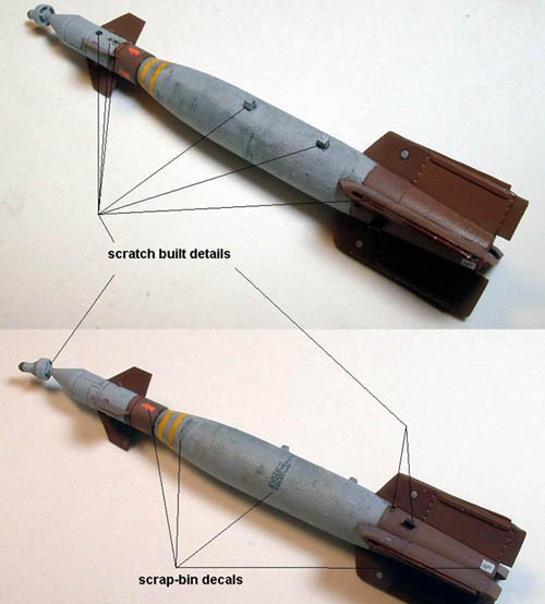
The AIM-120 was taken from Hasegawa’s 1/48 F-16C kit, and was further
refined with new surface details, new fins, cable conduit and exhaust
details. The forward fins were sprayed with a slightly metallic colour
before the edges were masked off and the centre painted flat black.
Decals came from Twobob’s AIM-120/AGM-88 sheet, which went on
beautifully but required minor trimming and adjustments for proper
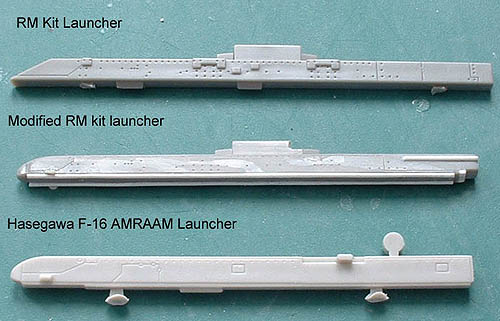
alignment. The AIM-120C pylon needed modification to better represent
the actual launcher.
Click the thumbnails below
to view larger images:
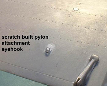
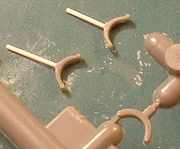
The empty outer pylon was detailed with scratch built mechanisms on the
lower surface. Sway braces on the empty fuselage station were also
reshaped a little. The inboard wing pylons were left off and the
associated mounting holes filled, rescribed, and an attachment eyehook
built just before the flaps.
Click the thumbnails below
to view larger images:
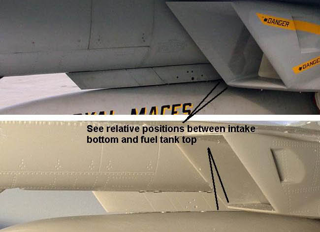
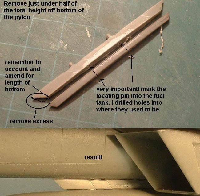
Someone pointed out to me that the kit centre fuel tank may be
somewhat too low as apparent by its relative height to the bottom intake
lip. After a bit of Mk.1 eyeball gauging, I removed just under half the
pylon height which allowed a more appropriate height for the tank. Note
that the leading and trailing edges of the pylon were flat and were duly
sharpened.
Click the thumbnails below
to view larger images:
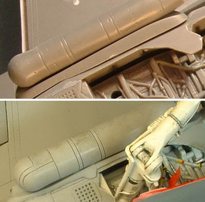
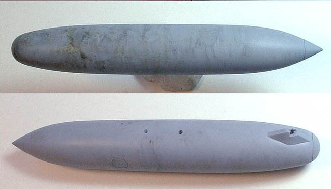
A significant amount of modification was needed on the AN/ASQ-228
ATFLIR pod and its fuselage adaptor. I’m not sure what Revell had as
references but certainly was not the ATFLIR. Much time was spent trying
to reshape the adaptor and the adjacent fuselage to achieve an
acceptable contour, as well the form the surface panel line details of
the pod itself.
Click the thumbnails below
to view larger images:
End of Part Two
Model, Images and Text by Copyright ©
2006 by John Chung
Page Created 06 March, 2006
Last Updated
06 March, 2006
Back to
HyperScale Main Page |
 Home
| What's New |
Features |
Gallery |
Reviews |
Reference |
Forum |
Search
Home
| What's New |
Features |
Gallery |
Reviews |
Reference |
Forum |
Search