|
Fiat G.50bis Freccia
by Werner Scheibling
|
 |
|
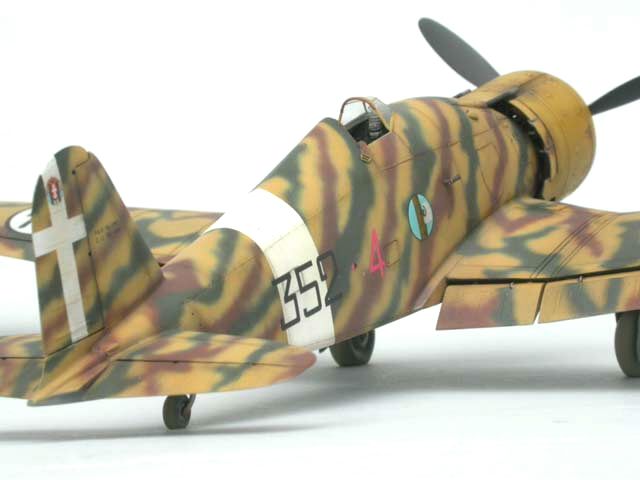
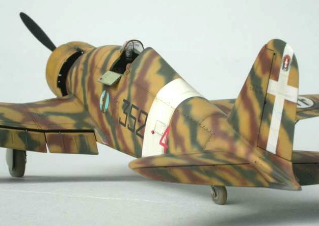
Fiat G 50bis
Serie V, MM. 5945,
20° Gruppo Autonomo C.T., 352a Squadriglia,
Martuba (Libya), June 1941 |

HyperScale is proudly supported by
Squadron.com
Italian Classic's full resin kit with additional
white metal and photo-etch parts is one of three options (next to
Hasegawa/Secter's injection-molded and Pacific Coast Models' mixed media
kit) available to those who want to build a Fiat G 50 in 1/48 scale.
Apart from being the most expensive, it is
unfortunately also the trickiest kit to build. It kept me busy for
nearly one and a half years nonstop.
If you calculate how much the average modeller
might spend on mainstream kits in that time, it's not such a bad deal
after all (does that sound a bit like an excuse?)
While talking about costs I should also mention
that it is almost essential to have access to the 'Ali d'Italia'
reference book on the Fiat G 50. This is where I found all the necessary
plans and information to figure out how the parts go together. The kit's
instructions are photocopies of hand-drawn sketches and are not very
helpful, to say the least.
Other 'musts' while tackling this kit are a
reliable electric tool with various milling and grinding bits, a razor
saw and - if possible - a set of calipers or a pair of dividers for
essential measuring.
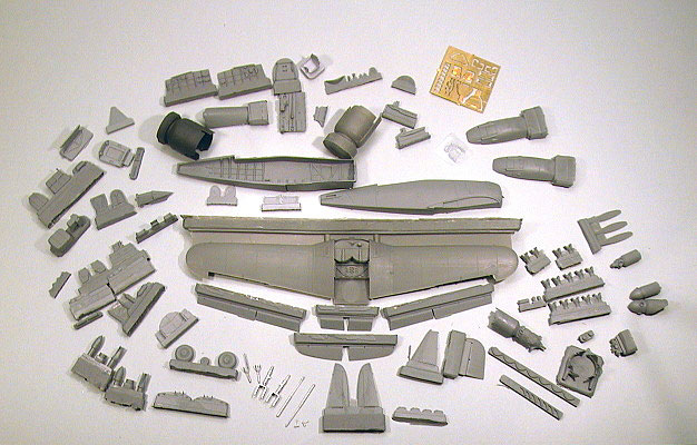
In an extremely sturdy cardboard box you'll find 150 resin, white metal
and photo-etch parts, tightly packed in several zip-lock bags. In
amongst this multitude are two types of cowlings (smooth or with rocker
cover bulges), two different gun-bay covers (small or large bulges),
both kinds of spinners (small or sand proof), both kinds of carburettor
air intakes (open or with sand filter) and finally underwing racks plus
bombs. In this way the kit allows you to build virtually any possible G
50bis/AS configuration.
The resin casting in my kit was unfortunately a bit
on the disappointing side – there were quite a few unnecessary casting
imperfections that needed hours of clean-up, and some nasty trapped air
bubbles where I least wanted them.
The material on the other hand is of very good
quality – strong, elastic and very break resistant. This makes the work
with very delicate parts, like the paper-thin landing gear covers, much
less nerve-wracking.
All important internal fuselage parts are represented, even a petrol
tank under the cockpit floor and several bulkheads that will disappear
forever in the fuselage unless you decide to build a museum style
cutaway model.
As the kit does not include a decal sheet it is necessary to find a
suitable after market set. I went for the 'Sky Models' sheet, printed by
'Cartograf', as it is readily available and of highest quality.
Sequence
The best way to build this very complex resin kit
is to break up the project into independent sub-assemblies which should
finally be joined together after they have been completely finished -
including painting and weathering.
I chose the following order:
-
cockpit
-
fuselage/wing/tailplane
-
engine/cowling
-
airbrushing and
decalling
-
undercarriage
-
final detail parts
(propeller, pitot and venturi tubes, aileron mass balances and trim
tab actuators.)
If I had decided to show my model with a detachable
gun bay cover (the parts are there and I was strongly tempted!) this
would have led to a further complex sub-assembly.
The decision to put all these nice resin parts into
the spares box was not an easy one. After hours of measuring with
calipers and dry fitting, I came to the conclusion that it would be next
to impossible to cut and assemble the involved parts so precisely that
the resulting panel lines wouldn't stand out embarrassingly.
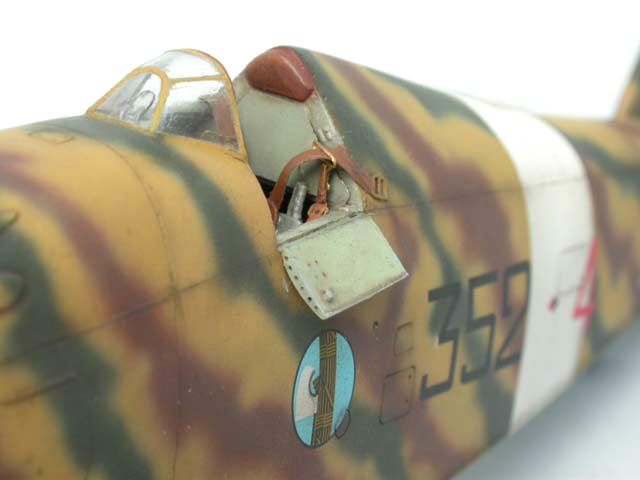
Leaving the gun bay cover off permanently would
have ruined the G 50's typical silhouette - the hump between cowling and
windshield being the type's giveaway recognition feature.
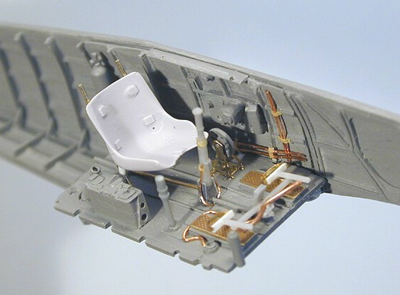
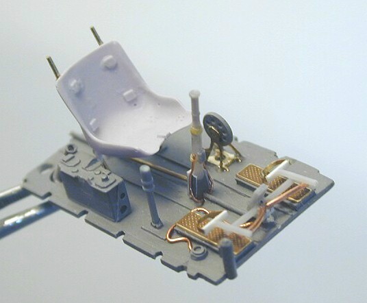
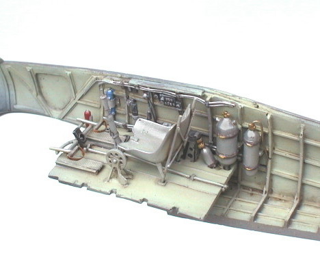
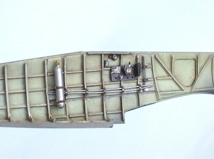
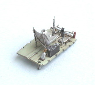
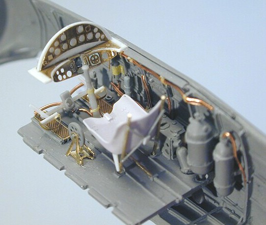
Cockpit
The inner fuselage side panels had to be cleaned up
before I could add all the necessary plumbing from copper wire in
various widths (0,1 - 0,3 mm). The castings of the four compressed air
and oxygen bottles behind the pilot's seat were bad and it took a whole
evening of creative sanding to achieve a halfway round appearance. I
painted these items a neutral metal colour as I could not find any
reference on their original colouring (if there ever was any). The real
G 50 needed all this compressed air for its pneumatic engine starter and
wheel brakes.
Click the thumbnails below to view larger
images:
Other parts like seat support frame, control
column, rudder pedal bar, instrument panel lights and various levers
were built from scratch.
The intricately curved and angled instrument panel
was created using Eduard's early PE set for the Hasegawa/Secter kit and
thin styrene sheet.
The pilot's safety harness is a generic item from
RCR's excellent PE set.
Fuselage/Wing/Tailplane
The casting of all involved parts is generally rich
in detail, but unfortunately very vague concerning precise dimensions.
It's not always completely clear where the part ends and the casting
block starts.
With lots of dry fitting and measuring against the
excellent scale plans in the 'Ali d'Italia' book I came up with the
following assembly sequence:
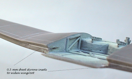
First the width of the fuselage has to be defined
via measurements taken from the one part wing (wing root to wing root),
from the front and rear upper fuselage deckings and from the tail cone.
Then the width of the cockpit floor has to be adjusted accordingly. As
you can see in the photos I had to insert slivers of sheet styrene along
the front bulkhead (which also serves as an attachment point for the
engine and should therefore be very sturdy), along the seam of the lower
fuselage and around the rear fuselage decking to make everything fit
properly.
Before both upper fuselage deckings can be
installed, it is vital to mark, on both fuselage halves, where the
pilot's small entrance doors will later go. These markings define the
position of front and rear fuselage decking and not vice versa!
Otherwise you might find out that the model is nearly finished and the
gap you left for the doors is too wide or too narrow...
The addition of tail cone, vertical and horizontal
tail surfaces completed the basic fuselage sub-assembly.
I reinforced the attachment areas of vertical and horizontal tail
surfaces and all movable flying surfaces with stubs of brass wire, to
make sure I could handle the assembled model safely.
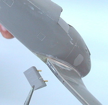
To the best of my knowledge, the one piece wing with separate flaps and
ailerons started its career as a replacement part ('corrected wing') for
the Hasegawa/Secter kit.
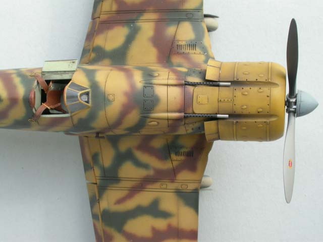
This is unfortunately the reason for one of the
kit's major assembly problems. It is also the only part that has raised
panel lines, which I removed and re-engraved. The two oil-cooler air
intakes are depicted as elliptical openings, whereas they should be
round. As one of the openings was badly miscast, I decided to drill them
both out and add the three-piece shutters from little styrene strips.
When I dryfitted the completed fuselage against the
wing I noticed to my horror that the rear section of the one piece wing
was nearly one millimetre shallower than the fuselage at that point,
resulting in either a matching lower fuselage or upper wing root
connection – but not both at the same time. I guess this is an
inheritance of the wing's earlier life as a replacement part for the
Hasegawa/Secter kit. But that certainly doesn't give you any comfort
while trying to build this resin kit. I wondered many times, also during
later stages, whether the master maker had actually ever tried to
assemble his own creation.
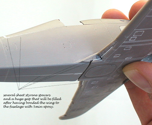
In the end I performed a deep and wide horizontal
cut with a cutting disc into the back of the wing and jammed slivers of
sheet styrene into the gap to widen the wing (see photo). Now the wing
had the right depth to follow the fuselage contours perfectly.
Ailerons and flaps were attached with stubs of brass wire that fitted
into pre-drilled holes. I used five-minute-epoxy throughout for these
connections.
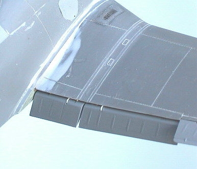
To give the lowered flaps an authentic sit it is
necessary to keep the following in mind: In reality the flaps moved
slightly down on hinges (visible from underneath) while they rotated
downwards. This resulted in a visible gap between the wing's upper
trailing edge and the flaps.
Click the thumbnails below to view
larger images:
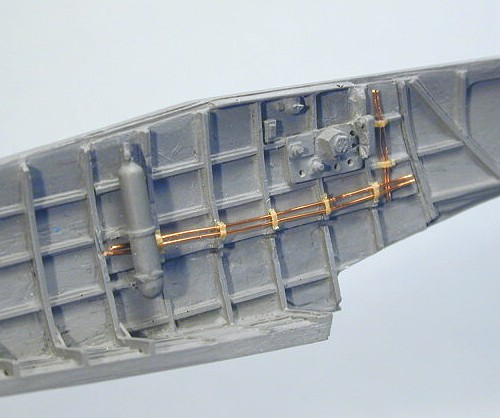
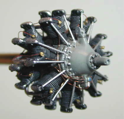
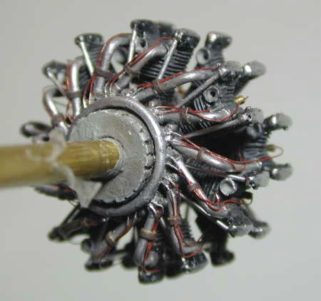
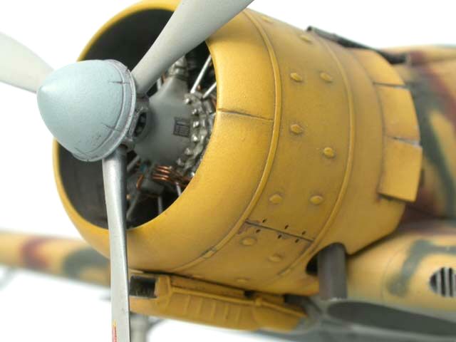
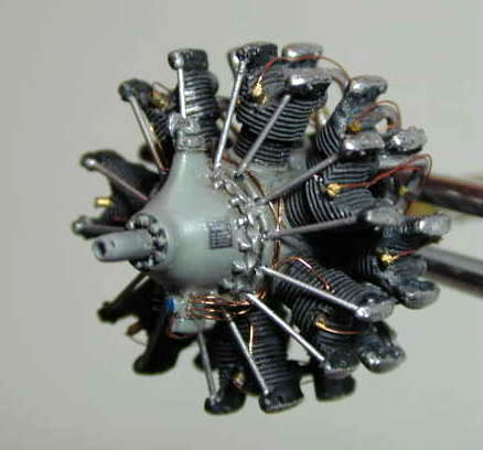
Engine / Cowling
Again all the necessary resin parts are there to
build a very detailed and complete Fiat A74 RC38 14-cylinder radial
(even with carburettor and magnetos if desired).
The only items needed to be added by the modeller
are OHV push-rods, which have to be cut to length from suitable round
material. I used 0,4 mm copper wire for that job.
Other scratch built items that I decided to add
were single oil feed lines that run from the reduction gear case to each
individual front row cylinder head, intake tubes and ignition harness.
All parts, especially the cylinders, have to be
exactly measured, filed to length and aligned to make sure the
peripheral parts fit to the cylinders and the assembled engine fits into
the cowling.
Click the thumbnails below to view larger
images:
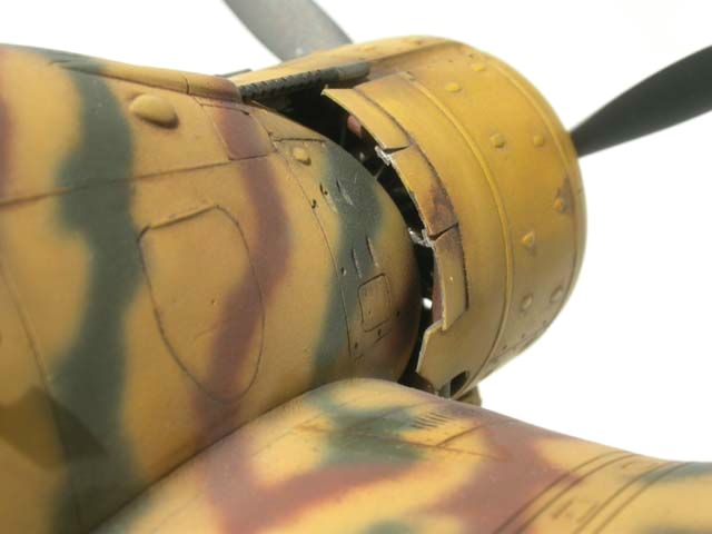
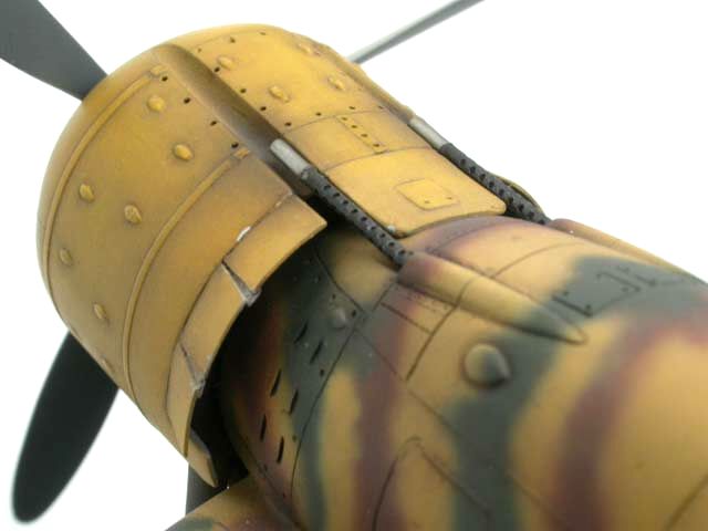
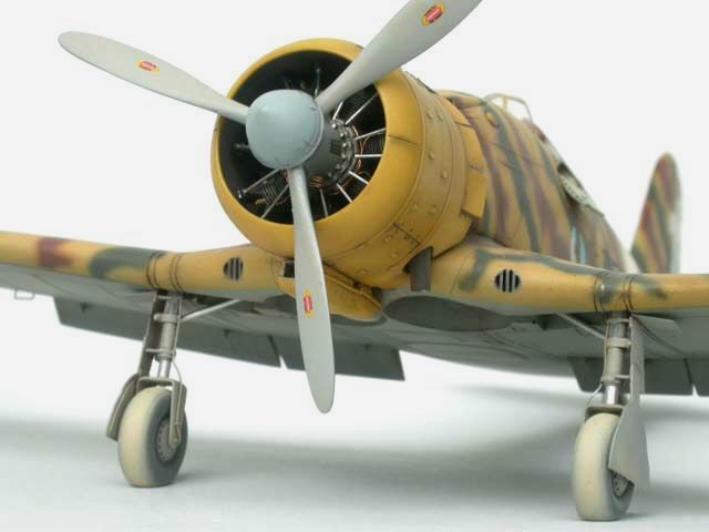
In my case this was the late style cowling with
bulges. After removing the massive casting block that engulfs both the
in- and outside of the cowl ring I modelled open cowl flaps from 'Dymo'-tape
to expose at least a tiny bit of the engine's rear.
The completely finished model engine was carefully
centered and aligned inside the cowling with the help of a template and
3 little slivers of styrene sheet, tightly fitted between cowling and
cylinder heads. This exact position was secured with some drops of
five-minute-epoxy and left to harden thoroughly.
The engine/cowling assembly was joined to the
airframe after both airbrushing and decaling were completely finished. I
was surprised about the perfect fit, something I had no longer expected.
A generous amount of five-minute-epoxy assured a durable connection.
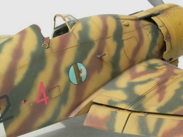
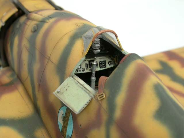
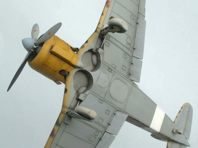
Airbrushing and Decaling
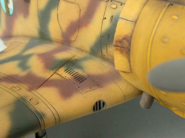
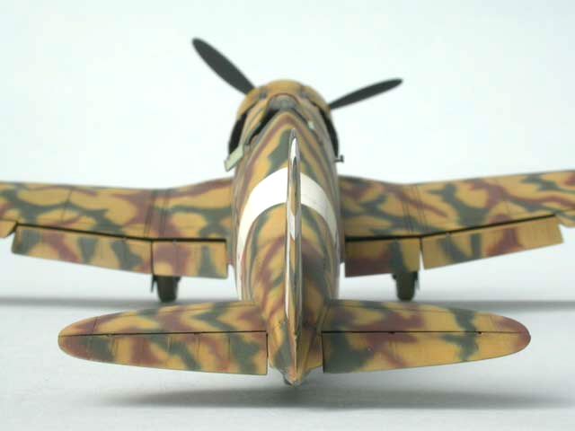
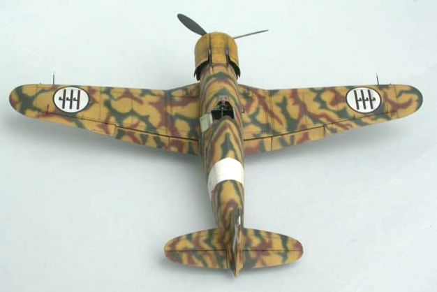
The Serie V of G 50bis built by Fiat's own
Aeritalia factory in Turin sported the standard three-tone upper
camouflage colours of Verde Mimetico 3 (camo green) and Marrone Mimetico
2 (camo red-brown) over a base coat of Giallo Mimetico 3 (camo yellow) –
this time not in spots, but in alternating diagonal stripes along the
fuselage and in ragged patches on the horizontal flying surfaces.
The undersurfaces were painted Grigio Mimetico (camo
grey).
The camouflage shades are my own slightly darkened
mixes from the range of LIFECOLOR 'Regia Aeronautica' acrylics. I prefer
to work with LIFECOLOR matt acrylics, as they flow incredibly fine and
evenly from my IWATA HP-BS airbrush and do not tend to clog the nozzle
too quickly. I found out that the trick is to keep the paint rather
thick and turn the air pressure up to 15-18 bar (~ 22-28 psi) – rather
the opposite of what is generally recommended for detail work.
First I sketched the intricate camouflage pattern
on photocopied scale planes, using the variety of published b/w photos
of '352-4' as a guide. These sketches were a great help airbrushing the
camo pattern free-hand later.
For the first time I tried Johnson's Klear (the
British version of Johnson's Future) as a gloss undercoat for decaling.
A test shot on a piece of LIFECOLOR-ed scrap went well so I got the Fiat
out. When the liquid touched the readily camouflaged model it curled up
into round droplets and wouldn't straighten out. After a few seconds a
milky white residue started to show. I immediately held the affected
area under running water to get rid of the mess before the Klear had any
time to cure. In the end I used PollyScale Semi-Gloss Clear with great
results, as all the other years before.
The decals went on beautifully without a trace of
silvering. Even the tiny Matricola Militare serial (MM. 5945), whose
digits had to be cut singly from the excellent 'Sky Models' sheet,
presented no problem.
Everything was sealed with a coat of PollyScale
Flat Clear.
Panel lines were accentuated with various shades of
dark brown pastel dust. Certain areas, like wheel wells and the yellow
cowling were additionally treated with light washes of 'burnt umber' oil
paint.
After several days of drying the model got one more final layer of flat
clear.
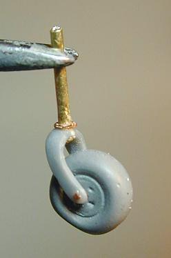
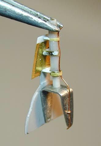
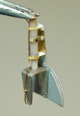
Undercarriage
To cut a long story short: The kit's white metal
parts, with the exception of the wheel forks, had to go straight into
the dustbin. The material is so soft, that the tail wheel couldn't
possibly carry the resin kit's weight. The parts themselves were so
shabbily cast, that I couldn't think of a single method to achieve
straight u/c legs with a round circumference from them.
So, I constructed new legs from styrene rod with a
brass wire core and attached the heavily reworked wheel forks with
five-minute-epoxy. This assembly was completed with the complex landing
gear covers, which are partly kit (resin, photo-etch) or scratchbuilt
items made from styrene sheet.
Click the thumbnails below to view larger
images:
The tail wheel fork was hand carved from an old
Tamiya Corsair part, attached to a brass wire strut.
All wheels are original 'Italian Classic' parts.
Final Details
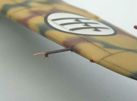
Two rather complex pitot tubes had to be
constructed from styrene sheet and rod plus 0,2 mm copper wire - these
are not provided with the kit.
As this aeroplane wasn't equipped with a radio set,
I didn't have to worry about aerial wires - which was nice.
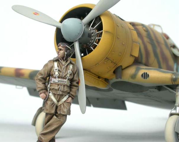
Finally, the proud pilot is from Mike Good's classic set 'Two Italian
Pilots WW II', which he did for Jaguar Models quite a few years ago.
Figures in that scale can't be sculpted more realistically than this
one!
Resources
-
'Italian Classic'
1/48 resin kit #006, Fiat G 50 Serie VII bis/AS
-
'RCR Models' 1/48
PE set #S16, Fibbie E Cinture Regia Aeronautica (Regia Aeronautica
buckles and belts)
-
'Eduard' 1/48 PE
set #48-032, Fiat G 50 for Secter kit
-
'Sky Models' 1/48
decal sheet # 48-026, Fiat G 50
Not really essential, but much better than the kit
parts, if you should come across them:
-
'Falcon Clear–Vax
Canopies' 1/48 scale set No. 37, WWII fighters pt.2, Fiat G 50
standard canopy (for Secter/Hasegawa kit) (o.o.p.)
-
'Aires' 1/48
resin/PE set #4009, Browning M2 .50cal (only resin barrels used)
Bibliography
-
'Ali d'Italia'
No.6, Fiat G 50, by Piero Vergnano,
La Bancarella Aeronautica, Torino / Giorgio Apostolo Editore, Milano
-
'Ali e Colori'
No.3, Fiat G 50 – I Colori Del Fiat G 50, Macchine-Piloti-Storie,
by Paolo Waldis, Marino De Bortoli, Angelo Brioschi
La Bancarella Aeronautica, Torino / Giorgio Apostolo Editore, Milan
-
'Profile
Publications' No.188, The Fiat G.50, by Gianni Cattaneo
'Dimensione Cielo', Immagini A1, Caccia Assalto, by Emilio Brotzu
and Gherardo Cosolo, Edizioni Bizzarri, Roma, 1972
(These interesting series of photo publications have recently been
re-published by
Aviolibri - IBN Editore - Instituto Bibliographico Napoleone, Roma
and show rare photos of Fiat CR.32+G 50, Breda Ba.65+88.
-
'Scale Aviation
Modeller International', Vol.7 No.2, Feb. 2001, Fiat G.50 'Freccia'
by Richard Caruana
-
Wings of Italy -
The Italian Airforce in Original WW II Colour Pictures,
by Gregory Alegi and Baldassare Catalanotto, Giorgio Apostolo
Editore, Milano,
ISBN: 88-87261-01-6
-
Colori & Insegne
Regia Aeronautica Caccia & Assalto 1940 -43, Parte I /
Camouflage and Markings of the Regia Aeronautica, Fighter and Ground
Attack Units 1940-43 Part One, by Paolo Waldis, Marino De Bortoli
and Angelo Brioschi,
La Bancarella Aeronautica, Torino / Giorgio Apostolo Editore, Milano
Click the thumbnails below to view larger
images:
Italian Aces of World War
2
Aircraft of the Aces 34 |
|
|
|
|
Author: Giorgio Apostolo
Illustrator: Richard Caruana
US Price: $19.95
UK Price: £12.99
Publisher:
Osprey Publishing
Publish Date:
November 25, 2000
Details: 96 pages; ISBN: 1841760781 |
|
|
Model, Images and Text Copyright ©
2004 by Werner Scheibling
Page Created 13 August, 2004
Last Updated
15 August, 2004
Back to
HyperScale Main Page
|
 Home
| What's New |
Features |
Gallery |
Reviews |
Reference |
Forum |
Search
Home
| What's New |
Features |
Gallery |
Reviews |
Reference |
Forum |
Search