|
1/48 scale
Grand Phoenix kitbash
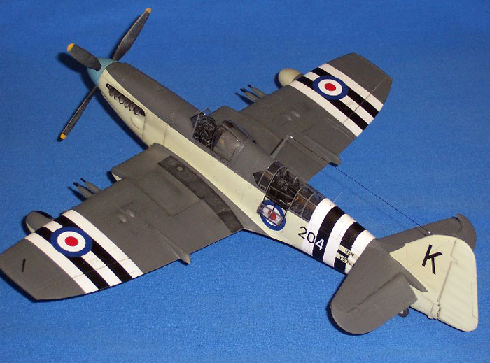
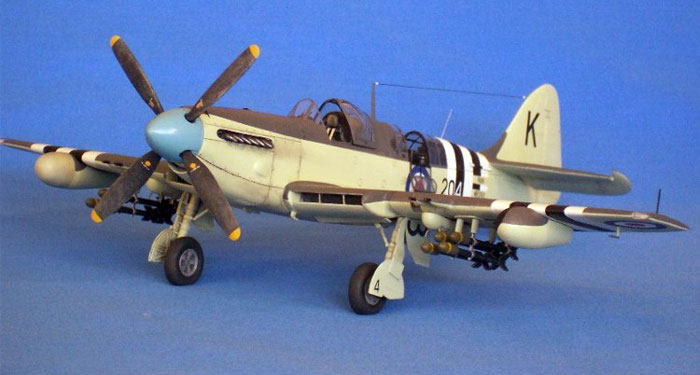
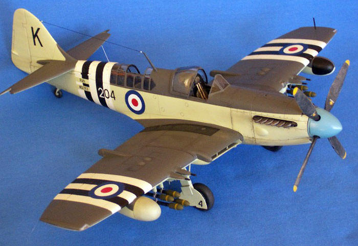
Fairey Firefly FR.5
by Mike Prince
|
 |
|
Fairey Firefly FR.5 |

HyperScale is proudly supported by Squadron.com
The Fairey Firefly was originally designed as a two seat naval
fighter to meet specifications issued by the British Admiralty in June
1940. Ultimately, this aircraft evolved into a true multi-role aircraft,
with various marks performing roles as diverse as fighter /
reconnaissance, night fighter, anti-shipping and anti-submarine warfare,
dual control trainer and, in later years, target tug.
The first Fireflies reached squadron service with the Royal Navy in late
1943 and were operational in time to participate in attacks on the
Tirpitz in Norwegian waters in July 1944. By late 1944 Fireflies were
operating with the British Pacific fleet.
Australian Service
In 1948 HMAS Sydney was commissioned into the Royal Australian Navy
(RAN), followed thereafter by HMAS Vengeance (on loan from the United
Kingdom) then HMAS Melbourne in 1955. Sydney’s Air Group initially
consisted of Hawker Sea Furies and Fairey Firefly FR5s, the individual
squadrons embarking in Sydney in 1949 following workup in the UK.
Ultimately, the RAN took delivery of 108 Fireflies, including two FR4s,
37 FR5s and 69 AS6s.
In October 1951 Sydney deployed to Korea to relieve HMS Glory with 805
and 808 Squadrons embarked, both equipped with Sea Furies, along with
817 Squadron equipped with Firefly FR5s. These FR5s were transferred
from other RAN squadrons as the cannon armament of this version was
considered to make it more suitable for operations over Korea than the
AS6s with which 817 Squadron had previously been equipped. Roles
performed by the Fireflies included spotting for naval bombardments,
dive-bombing of rail targets, bridges and other transport
infrastructure, attacks against troop concentrations and armed
reconnaissance. A number of aircraft were lost or damaged by enemy
ground fire, whilst the hazards of operating from a small escort carrier
also took their toll. Operations continued until 31 January 1952.
Attrition replacements were drawn from Royal Navy stocks both during the
deployment and during the return passage to Australia. Following a
subsequent deployment to the UK and return via the United States, Sydney
conducted a second deployment to Korea from November 1953 to June 1954,
this time contributing to enforcement of the truce signed between North
and South Korea in July 1953. No combat flying was undertaken during
this second Korean deployment.
With the arrival in Australia of Melbourne with a Carrier Air Group
consisting of DeHavilland Sea Venoms and Fairey Gannets in late 1955,
both the Furies and Fireflies became obsolete. Between 1957 and 1959 the
vast majority of Fireflies were retired from service, though a number
soldiered on as target tugs until the mid 1960s.
The Kit
I have long wanted to build to models of the aircraft operated by the
RAN, preferably in 1/48 scale. A few years ago Grand Phoenix released an
excellent model of the Firefly Mk1, however, with its beard type
radiator, shorter fuselage, three bladed propeller and lack of radar and
fuel pods on the wings, it was not entirely suitable. Whilst rumours of
a kit of a later mark abounded, no injection moulded kit of a more
suitable version has appeared to date. Therefore, it was time to
undertake some relatively serious kit-bashing to convert a Mk1 into an
FR5 as used by Sydney in Korea. As no conversion kit was available, this
was undertaken using sheet styrene, parts from the spares box, and a
degree of lateral thinking. Whilst this conversion might initially
appear complex, once a solution had been identified for each discrete
step, there was nothing that was ultimately too difficult.
Summary of conversion
-
Fuselage: Lengthened 8mm using
plastic sheet between windscreen and firewall. Wing fold braces
added to rear fuselage. Various bulges and vents added to upper and
side cowl panels.
-
Lower cowl: “Beard” type radiator
removed, new carburettor intake and lower cowl built up using
plastic sheet. Revised cowl panel lines scribed.
-
Spinner: Kit spinner re-profiled from
rounded to pointed and converted from three bladed to four bladed
arrangement. Backplate modified to match.
-
Propeller blades: Scratch built from
8 Academy Spitfire Mk XIV blades.
-
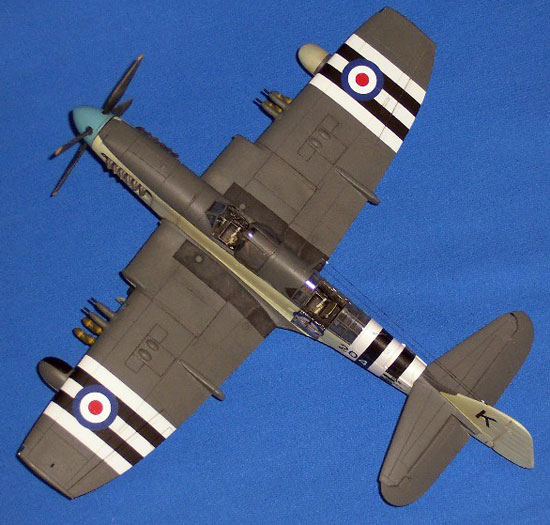
Wing radiators: Scratch built from
sheet plastic, sections from discarded wings and brass wire.
-
Wings: Wing tips clipped, landing and
navigation lights cut out and replaced with clear lenses, landing
light from scrap, (wing spar built to compensate for sections
removed to accommodate new radiators). Rockets from spares box.
-
Fin: Straight leading edge removed
and replaced with extended leading edge and fillet. Actuating rod
added to rudder trim tab.
-
Tailplane: Elevators separated,
balance horns altered from 45º
to fore / aft alignment.
-
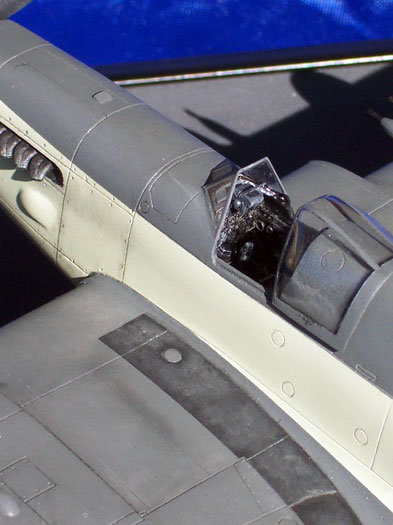
Front cockpit: OOB except for
gunsight from spares box and windscreen replaced from clear sheet.
Canopy runners added.
-
Rear cockpit: OOB except for canopy
cut open, with open sections replaced from clear sheet.
-
Markings: Roundels and parts of
aircraft serials from Eagle Strike “Sea Fury Pt 1”, black and white
side numbers from Aussie Decals (generic), remainder of serials hand
painted.
Fuselage (1)
The fuselage was initially built as per the kit instructions, though
the resin exhausts were left out as they were at risk of being damaged
when conversion of the nose was undertaken later. The resin components
for the two cockpits were painted extremely dark grey (almost black) and
dry brushed with a lighter grey and silver. The two small levers either
side of the pilot’s seat were replaced with wire, the etched seat belts
were painted and installed, and the instrument panel assembled then
fitted. Dry fitting showed that only a little thinning of the completed
cockpits was necessary, after which the two fuselage halves were joined
and the aft cockpit glued in, though the forward cockpit was left loose.
Before addressing the changes to be made to the fuselage the fuselage
and forward cockpit were then put aside while the internal structure of
the wing was addressed.
Wings (1)
Having completed the fuselage more or less as per the kit
instructions so far, the first stage of building the wings was
undertaken. First up, the mating surfaces of the upper and lower wing
halves were sanded smooth. The tops of the resin wheel wells were
thinned to allow the upper and lower wing surfaces to mate, then once
correct, the wheel wells were glued to the lower surface.
The next few steps were then developed to ensure that the relationship
of the wings to the fuselage would be maintained once the leading edges
of the wings and the lower front fuselage were removed a little further
down the track.
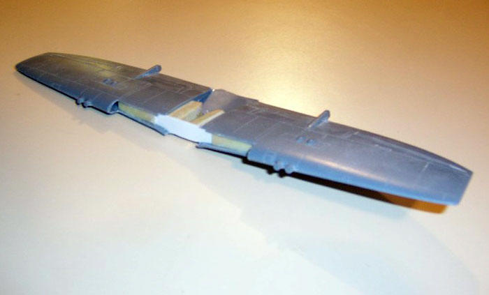
To maintain the dihedral already moulded into the kit’s lower wing, a
main wing spar was fashioned from sheet styrene and fitted to the
forward faces of the wheel wells where it would later be enclosed and
hidden. Next, the upper and lower wing surfaces were taped together and
the depth of this spar, and the thickness of the resin on the base of
the forward cockpit, were both repeatedly filed and dry fitted until the
wings fitted the fuselage correctly.
Following this, the leading edges of the wings were cut away from 2mm
inboard of the wing fold lines. On the lower surface care needed to be
taken not to interfere with the resin wheel wells and the new wing spar
on the forward face. The lower fuselage area immediately ahead of the
wheel wells was also removed where the kit’s wing was shaped to fit the
aft end of the beard radiator. Finally, the upper and lower wing skins
were glued together and, once set, the wing tips removed approximately
4mm outboard of the outer end of the ailerons. This excess was then
filled and filed to shape to represent the clipped wingtips of the later
marks of the Firefly. Concurrently, the opportunity was taken to thin
the trailing edges then re-scribe any lost detail. At this point, the
focus of work returned to the forward fuselage.
Fuselage (2)
The forward cockpit was permanently fitted in the fuselage at this
stage. Next, the nose was separated from the fuselage using a razor saw
to cut vertically mid way between the two vertical panel lines
immediately behind the engine exhausts. The lower cowling was also
removed; cutting along what would eventually be the new panel line
dividing the new lower cowl from the side panels. It should be noted
that this panel line lies further down the fuselage than on the Mk 1,
the panel line ending mid way down the wing radiator openings rather
than above the wing as on the earlier version. Side views of the
aircraft show this quite clearly once the difference has been
identified.
A 38cm stretch was included on versions of the Firefly following the Mk1
to counteract the additional weight of equipment fitted to the
observer’s cockpit. The fuselage was therefore extended 8mm using sheet
styrene glued inside the fuselage to provide some structure, with a
second 8mm wide strip wrapped around the outside to fill the resultant
gap. Once this strip was faired in and the panel lines replaced, the
kit’s resin exhausts were then fitted through the new opening in the
lower cowl. The prominent flame dampers over the exhausts were left off
as these were not fitted to all aircraft, and seemed to be rarely fitted
to FR5s.
Finally, the leading edge of the fin was removed, then the fin extended
forward using sheet styrene to reflect the curved leading edge and large
fillet that characterised Fireflies from the FR4 onward.
Wings (2)
Having extended the fuselage the wings were then fitted to the
fuselage with the primary mating surfaces being the wing upper surfaces
to the wing fillets, and the wing spar to the base of the resin cockpit.
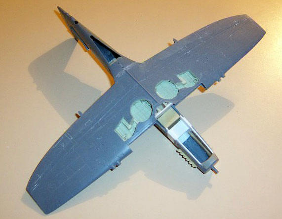
Nose
The lower cowling of the nose was blanked off using a single layer of
sheet styrene to form a base for further construction. To this was added
a new carburettor intake below the spinner, resulting in an intake about
3mm deep. The remainder of the lower cowl was then built up using
successive layers of sheet styrene, extending in a smooth curve all the
way back to the wheel wells. Once complete this was carved, filed and
sanded to shape, with a coating of CA glue used as filler to ensure that
the edges of each layer would not be visible once the model was painted.
Finally, the inner ends of the wing radiator housings were shaped from
two layers of sheet styrene and glued to the sides of the nose ahead of
the cut down wings. These were cut so that they extended forward until
mid way between the two vertical panel lines immediately behind the
exhausts, and created a blunt airfoil shape extending forward from the
existing upper and lower wing surfaces.
Radiators
The radiator housings were built by shaping and fitting the upper
surfaces, then hanging the internal details off the lower (inner)
surface. This consisted of the outer end of the radiator housing, a
styrene strip running span-wise to represent the front and rear faces of
the radiator, an inner surface for the radiator outlet (attached to the
lower wing skin just ahead of the wheel wells), then the lower skin of
the radiator housing.
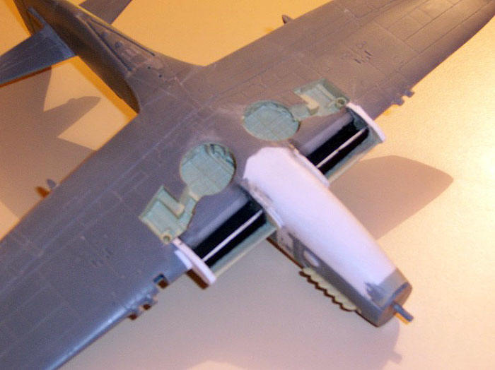
The upper and lower radiator skins were cut from the upper and lower
surfaces of wings from the spares box, in this case from an Airfix MkV
Spitfire, as there was potential for sheet styrene curved to the same
shape to warp as a result of handling. The outer ends of the radiator
housings were then faired in, the bracing visible in the radiator inlets
fitted by drilling and inserting brass rod through the lower surface,
then outlet doors made from styrene sheet and fitted.
Propeller and Spinner
Whilst the Mk.1 Firefly had a rather bulbous spinner and a three
bladed propeller, the spinner on later marks was much more pointed,
while the propeller was four bladed, with each blade considerably
broader than the finely tipped blades of the earlier version.
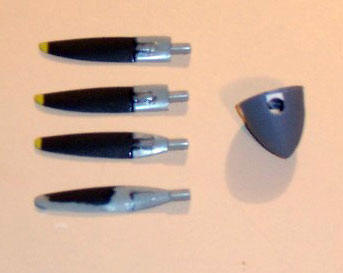 The
spinner was first converted to accept four blades, with two of the
existing three holes for blades filled then reinforced internally, then
three new holes cut and filed to the same shape as the one remaining
original hole. The spinner was then re-profiled from the existing
bulbous shape to something much pointier. The thickness of the plastic
allowed this to be done with a file. Finally, four small pieces of
styrene were glued to the back-plate behind where each propeller blade
was to be later fitted. These were then filed to shape so that when the
spinner and back-plate were joined, the hole for each blade was round
rather than “U” shaped. The
spinner was first converted to accept four blades, with two of the
existing three holes for blades filled then reinforced internally, then
three new holes cut and filed to the same shape as the one remaining
original hole. The spinner was then re-profiled from the existing
bulbous shape to something much pointier. The thickness of the plastic
allowed this to be done with a file. Finally, four small pieces of
styrene were glued to the back-plate behind where each propeller blade
was to be later fitted. These were then filed to shape so that when the
spinner and back-plate were joined, the hole for each blade was round
rather than “U” shaped.
The propeller blades were tackled next. Although my spares box has lots
of propeller blades that rotate to the right, Fireflies were fitted with
a Griffon engine that rotates to the left (as per a late mark Spitfire
or a Typhoon). To solve this I found that I could make a broad enough
and long enough propeller blade by splicing together two blades
discarded from an Academy Mk14 Spitfire kit, using eight blades in total
to make the required four. I think a spare four bladed propeller from a
Typhoon kit would have been much simpler; unfortunately none was
available. Once set, the blades were filed and sanded to shape to match
the references.
Radar Pod and Wing Fuel Tank
Almost all Fireflies from the FR4 onward were operated with a surface
search radar in a pod on the starboard wing, with fuel contained in a
similar pod on the port wing. Photographs taken onboard the Sydney off
Korea indicate only a few FR5s without these fitted. However, around
half my reference photos of restored Fireflies show the aircraft without
them.
The front portions of these were constructed from the “aluminium” drop
tanks of an Accurate Miniatures P51 (the diameter of the “paper” drop
tanks in other kits is too small). All detail was removed and the
diameter reduced slightly at the widest point. The back third of the
drop tank was then cut off and the length extended with sheet styrene to
create a long and streamlined pod. Finally, the top of the pod was cut
to roughly match the shape of the wing’s lower surface. This cut-out was
refined by wrapping the wing in sandpaper (rough side outward), then
sanding back the top of the pod using the wing to define the shape.
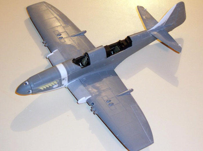
Additional Details
Two bulges on the sides of the engine cowlings were cut from sheet
styrene, shaped, fitted and faired in. A small inlet was fitted on the
top of the engine cowl. Louvres on the lower cowl were cut in and shaped
using a sharp blade. The elevators were separated from the tailplanes,
with the balance horns reshaped so that the extreme tips point directly
forward. The trailing edges were thinned. The coamings of the pilot’s
cockpit were extended upward to include runners for the canopy. The
kit’s gun sight was replaced with a gyroscopic sight from the spares
box, with a small piece of acetate used to model the reflector. The
landing light was cut out, boxed in then built up with scrap plastic,
then covered with clear acetate curved to shape, while the navigation
lights were cut out and replaced with sections of clear sprue that were
later filed to shape and polished. Catapult hooks were fashioned from
scrap plastic and fitted beneath the fuselage just inboard of the
radiators. The pilot’s windscreen was replaced with a scratch built item
from clear sheet, while the rear canopy opened up with the opening
panels then replaced with new items rolled to shape from the same clear
sheet.
The kit’s cannon barrel fairings were replaced with sections of round
sprue, cut to length and sanded to shape, with the protruding barrels
fashioned from brass tube. The mounting panels for the rocket rails were
cut from thin sheet styrene, with the rockets coming from the spares
box. The bomb carriers were shaped from underwing gun pods from an old
Monogram T-6 Texan kit, reduced in both depth and length. A pitot tube
was sourced from the spares box and cut down for fitting under the outer
port wing after painting.
Ultimately, I wanted an RAN aircraft wearing Korean War stripes. This
was easier said than done.
My primary reference only included a profile of FR5 WB377 / 201K as
operated by 817 Squadron from Sydney during the first Korean deployment.
However, this was an attrition replacement borrowed from the Royal Navy.
The profile loosely follows photos available from the Australian War
Memorial that show the aircraft on deck in a damaged state following
Typhoon Ruth on 15 Oct 51. In these photos, the “1” of “201” has been
over-painted by the leading black fuselage stripe, presumably to be
replaced by a white “1” in due course. (Note that Typhoon Ruth occurred
during the first few days of operations.) This would agree with photos
of other aircraft on deck where the side numbers are black on white /
sky and white on black. It also agrees (in part) with photos of the
restored WB518, purportedly in the markings of WB377, though with the
aircraft’s true serial used instead. Further, the profile does not
depict the medium blue spinner denoting aircraft from 817 Squadron, as
shown on the restored WB518 and on the example in the Museum of Flight
at Nowra. On both WB518 and the Nowra example the wing stripes are
further inboard than on the original 1951 photos of WB377 (and all but
one other Firefly photographed during the 1951-52 deployment).
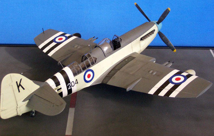
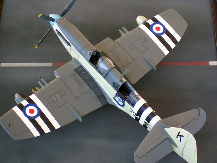
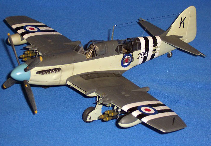
In order to model an RAN aircraft, I chose to depict FR5 WB393 / 204K,
which was downed by ground fire while operating over Korea on 26 October
1951. Fortunately, the pilot made a successful forced landing, albeit
behind enemy lines. After being protected for the remainder of the day
by aircraft from Sydney and Meteors from 77 Squadron RAAF, the crew;
LEUT Neil MacMilland and CPO Phil Hancox, were rescued in fading light
by the USN helicopter embarked on Sydney. I have assumed the aircraft
was in the same common scheme of Extra Dark Sea Grey and Sky with blue
spinner, black and white stripes around the outer wings and aft
fuselage, with the side numbers contrasting the fuselage stripes and
prominent serials beneath the wings that have been partially obliterated
by the stripes. Roundels and parts of aircraft serials came from Eagle
Strike’s “Sea Fury Pt 1” sheet, with the black and white side numbers
from Aussie Decals (generic). Remaining parts of the aircraft serials
were hand painted.
-
Sea Fury, Firefly and Sea Venom in
Australian Service, Stewart Wilson, Aerospace Publications Pty Ltd,
1993
-
Tale of Two Fireflies, Flightpath,
Vol 14 No.2, November 2002 – January 2003
-
The Journey, Aeroplane, Vol 30 No.11,
November 2002
-
ADF-Serials.com
-
Australian War Memorial
Click
the thumbnails below to view larger images:
Model, Images and Text Copyright ©
2005 by Mike Prince
Page Created 30 June, 2005
Last Updated
29 June, 2005
Back to
HyperScale Main Page |
 Home
| What's New |
Features |
Gallery |
Reviews |
Reference |
Forum |
Search
Home
| What's New |
Features |
Gallery |
Reviews |
Reference |
Forum |
Search