|
R.V. Resin
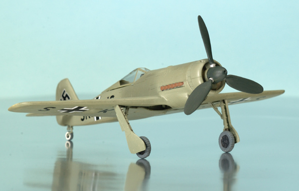
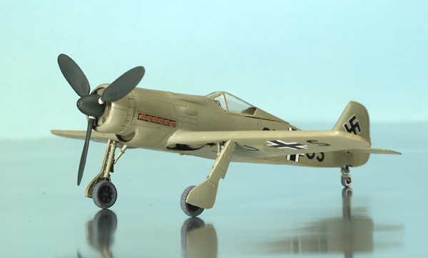
Fw 190 V13 (C-0)
text
and photography
by Jeff Harrison
|
|
|
Fw190 V13 (C-0) |

HyperScale is proudly supported by
Squadron.com
The FW 190 was an excellent fighter
almost from the beginning. There were significant problems with the
early FW190A-0 aircraft in the form of almost constant engine
overheating that nearly ended the program before it began. After solving
those problems though it proved to be superior to its contemporaries.
Its only weakness was at high altitude which also happened to be where
it would be most needed. To overcome these deficiencies three programs
were instituted. The FW 190B, FW 190C and FW 190D series. The B-series
aircraft were to use the BMW 801D-2 engine and experimented with
pressurized cockpits, superchargers and GM-1 boost. Results never
progressed past the earliest test phase. The C-series differed from the
B-series primarily in the use of the DB603A engine with a ring radiator
on the nose and an oil cooler mounted below the engine. The D-series was
intended to be an interim model with moderately improved altitude
performance and utilizing the Jumo 213 engine. The FW190C series had the
potential to become a very effective high altitude fighter but suffered
the same problem as the emerging German jets in not having suitable
metals to make a truly reliable supercharger or suitable high quality,
high octane fuels.
There is a lot of conflicting information about this plane. All agree
that it was Wk. Nr. 0036, was the first FW190C prototype and carried the
codes of SK+JS. Beyond that you can pick the story you like best. Some
sources claim that this airplane was first used as one of the FW190B
prototypes and at that time was fitted with the GM-1 system. After that
program was disbanded it became the first of the FW190 C prototypes.
Likewise some sources say the plane was armed with two MG 17s in the
upper cowl and two MG 151s in the wing roots while other sources say it
was unarmed. One sources says that it got the larger wing that was to be
tested on the 190B while the only set of official-looking drawings of
the plane show it with the standard 190A wing. The problem with these
airplanes is that the very nature of their mission means that it’s
possible that all of these sources are correct as the configuration of
the plane could vary significantly from one flight to the next.
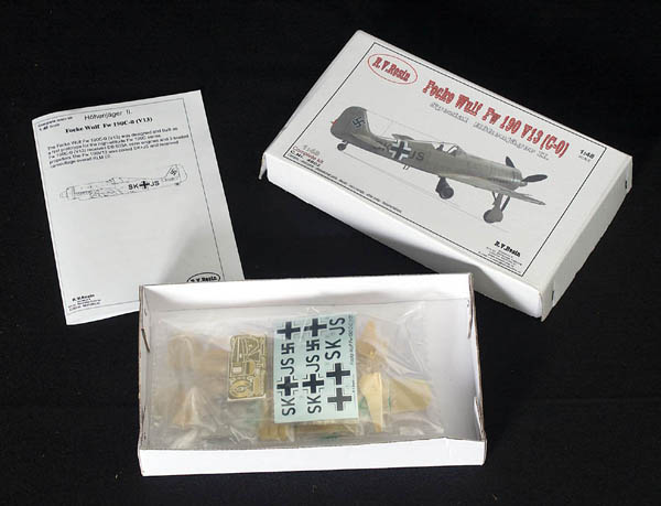
This R.V. Resin kit comes in a sturdy
white cardboard box. Upon opening you are confronted with a neatly
packed plastic bag that is subdivided into individual compartments for
nearly every piece.
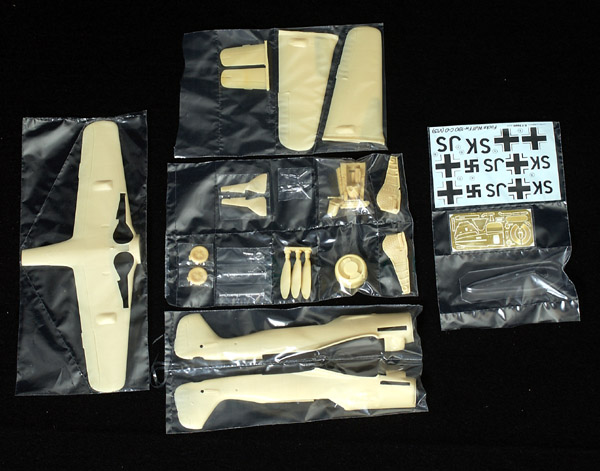
This kit is a multimedia kit consisting of a total of 24 resin, 5 white
metal, 1 PE fret with 21 pieces and a vac canopy. All of the major and
some of the minor parts are resin, white metal is used for the landing
gear and photo etched brass for some of the details. It appears to be
based on the Tamiya FW190A-3 kit. The major resin pieces are well cast
with few flaws and fine engraved surface detail. The only down side of
that surface detail is that it is also covered with the dimples that are
rapidly becoming the “new” fad for simulating rivets. The smaller resin
pieces and the white metal landing gear appear to be direct, though
crude, copies of the Tamiya parts. The instruction sheet could be
better. It consists of a single 8"x11.5" piece of paper folded in half
giving a total of 4 pages. The first page gives a very brief history of
the plane plus contact information for R. V. Resin. Page two gives an
exploded view of the model showing you less than half of the pieces
included in the kit. Page three consists of a top and left side view
plus scrap views of the bottom of the wings to show decal placement and
painting instructions. The last page gives you a list of currently
available and upcoming 1/48 scale releases. Basically you’re on your own
when building this kit.
I’ve been building models for close to 38
years now and for most of that time I’ve heard the admonition to wash
the parts before assembly. In all that time this is the first model I’ve
ever come across where that was absolutely true. I tried doing some
basic dry-fitting and I couldn’t get the tape to stick. Bottom line –
WASH THE PARTS BEFORE YOU BEGIN.
I used Zap-A-Gap CA+ for almost all construction on this project. I
started assembly by glueing the fuselage halves together. I noticed that
the fuselage seems to be a little bit wide in the cockpit (externally)
and the vertical stabilizer seems a little fat. You might want to sand
the mating surfaces of each fuselage half to correct this. Be careful
though because the cockpit tub does fit as is and so does the nose piece
so don’t remove too much. Anyway I started by glueing the tail together.
After making sure everything was lined up and the glue set I then
proceeded to glue the rest of the fuselage together working my way
towards the front. The only alignment problem I ran into was in the tail
wheel well.
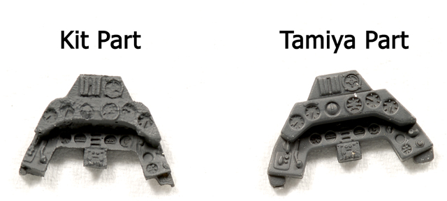
Next was the cockpit. If you’ve built the
Tamiya 190A-3 you’ll recognize these parts. Most are direct, if somewhat
crude copies.
The rudder pedals are replaced with PE
ones though they did not give you anything to mount them to, nor do they
show them in the instructions. If you wish you can use the Tamiya rudder
pedals that are a drop in fit (when copying the cockpit tub they did not
change it leaving the slot for the Tamiya rudder pedals). The instrument
hood is also a PE piece. You have to bend it to shape which requires a
lot of trial fitting and they don’t mention it but there are two tabs at
the “bottom” of the side pieces that should be bent out. It looks like
the fit inside the fuselage sides but really they should rest on top of
the cockpit opening to get it to sit at the correct angle. The
instructions show the head armor with a rather vague “it goes here”
arrow but the V-13 didn’t have it fitted so ignore it. I would recommend
that you do not install the exhaust pieces or the PE oil cooler at this
time. Save that for just before attaching the nose and preferably after
painting the airplane.
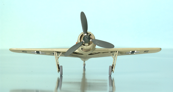
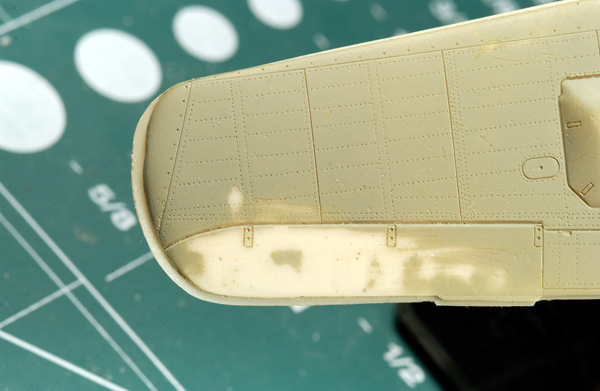
The dihedral angle of the wings is too flat so if you want to fix it now
would be the time to do so. Probably the best way would be to grind out
a channel down the middle of the wing (on the inside) then heat it in
hot water and bend it to the correct angle. After correcting the wing
install the two wheel well halves. Do not attach the top wing halves at
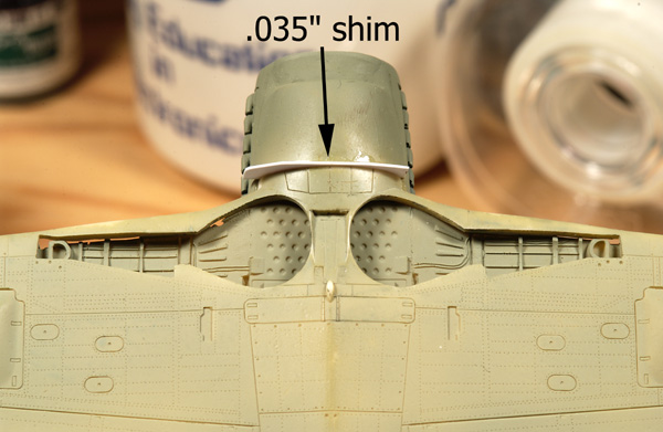
this time. The next step you’ll want to do is attach the bottom half of
the wing to the fuselage. In my sample the wing was .035" shorter than
the opening that it fit into. Start at the trailing edge and glue the
wing to the fuselage. Let the back half dry then bend the front half
down and glue it to the fuselage. Finally inset a .035" shim between the
leading edge of the wing and the oil cooler flaps then trim to shape.
Now you can attach the top halves of the
wings to the bottom half. You’ll need to remove more off the root than
the amount they indicate on the part. I had to remove resin all the way
to the inboard edge of the cannon bulges and even then the wing was
longer than the bottom piece. This is a good thing though because when I
was measuring the major components I found that the wingspan of the
lower wing was too short. The amount that the top wings extend past the
bottom half brings the span out to the correct length. After the wings
have dried just build up the lower wing to match the top wing.
The next step I did was to attach the horizontal stabilizers. You’ll
find that they don’t fit at all. The fin has small stubs cast on it that
the stabilizers are supposed to attach to like on the Tamiya kit.
Problem is that the stabilizers don’t have notches cast into them so you
end up with the inside edge of the elevators much too far out from the
fin and the stabilizers looking like they’re stuck on pedestals (which
they are). There are three fixes for this. 1] you can cut the
appropriate notch out of the stabilizers, 2] you can carve off the
offending pedestals (which is what I did) or 3] you can modify and use
the Tamiya stabilizers in place of the kit ones. Regardless of what you
do I strongly recommend that you drill a small hole in both the
stabilizer and the fin and use some .010" brass wire to pin them to the
fin. The joint isn’t very strong if you don’t and getting them aligned
properly without doing that is a royal pain–ask me how I know :-). With
the brass wire you can bend them into the proper position then apply CA
once you’re ready.
If you haven’t been taking care of the seams as you’ve gone along I
recommend that you do so now. Overall the fit of the kit isn’t that bad
so there should not be any terrible seams (except the wing tips). After
cleaning up the seams paint at least the nose section RLM 02 before you
continue. The next construction step will be to paint and install the
exhaust stacks and the oil cooler PE. Once that is done you can install
the nose radiator section. Alignment is a little tricky so align the top
center section with the “protrusion” on top of the nose, rotate the nose
piece around that to center it and add glue.
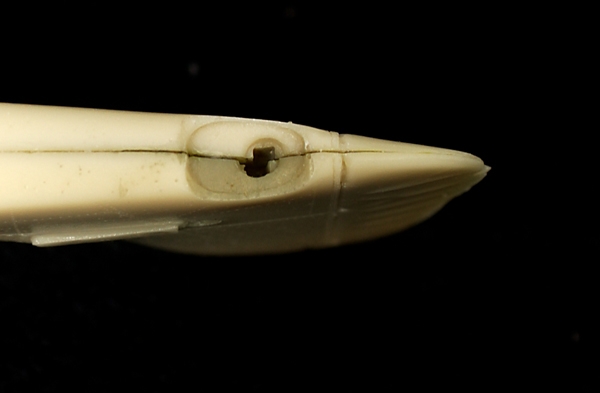
Finally we’re up to the little bits and unfortunately some of the worst
of the fit problems. The canopy simply does not fit properly and I’m not
exactly sure why. One of the problems is that one of the few pictures of
this airplane is a side view that clearly shows how the windscreen fits
in relation to the top of the cowl. It should fit flush with the top of
it and in the kit it ends noticeably below that point. Likewise to fit
at all over the instrument hood it leaves a noticeable gap between the
moving section of the canopy and the fuselage. If you open the canopy
none of this will be a problem but there isn’t really a suitable fix if
you want to show it closed. I guess the best method to do that would be
to not install the rear deck PE until you’re ready to install the
canopy. Then you can first build up the rear deck with a styrene shim to
get the canopy to fit then install the PE part (I didn’t know it
wouldn’t fit until I was nearly finished so it remains uncorrected in
this build). The main landing gear and gear doors are direct copies of
the Tamiya parts. They’re crude and not perfect copies which leads to
some fit problems. The main struts hade a notch cast into them that
Tamiya uses to position the gear doors. On the Tamiya doors there is a
corresponding tab that fits into this notch, the kit parts do not have
this tab and as a result really have no point to attach the door to the
strut. The struts themselves have square ends to aid in properly
aligning them when attaching them to the wing. Unfortunately the wheel
well inexplicably uses a “D” shaped hole for the same purpose which
gives you a classic “square peg in a round hole” mismatch. To get the
struts to fit I carved the outer corners of the square off so that they
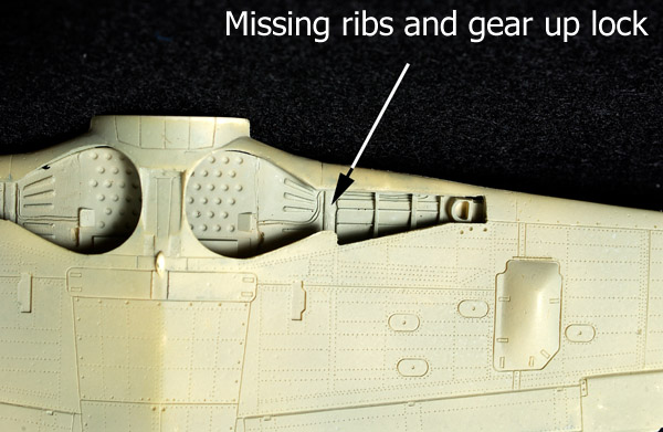
would fit into the hole. The retraction arms do a good job of getting
the struts into the correct angle though you do need to remove a small
portion of one of the ribs in the wheel well to let them fit properly.
After the landing gear all that remains is to paint and install the
radiator faces then build and attach the propeller. The propeller needs
a backing piece added. I made one out of a .035" piece of styrene that I
cut roughly to shape and glued to the spinner. Once attached to the
spinner you can finish shaping it. The prop blades are much too big at
the hub to fit into the spinner with the backing plate and need to be
trimmed but there are no real difficulties in assembling the propeller.
Paint
As far as challenging paint schemes go
this isn’t one of them. The airplane is basically 02, 02, 02 and 02 with
a little 70 thrown in for variety. Most production examples of the FW190
have a RLM 66 cockpit but this airplane is one of the earliest of the
early airframes and probably was painted 02. It’s possible that they
repainted it at some point but personally I have a hard time believing
that they would have. I painted the cockpit 02 with 66 used for the
instrument panel, instrument hood and various panes on the side
consoles. The stick has a leather boot, 02 column and black grip. The
seat was painted 02 with a leather seat cushion (I used Raw Umber oil
paint for the seat cushion, boot on the stick and “gaiters” of the main
landing gear). The seat belts are off white with silver hardware and
leather pads on the lap belts.
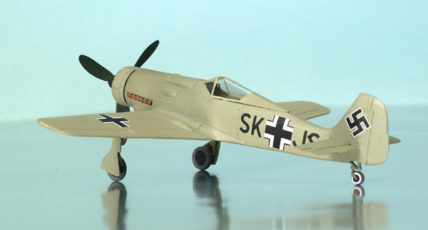
The rest of the airframe is overall
Xtracolor RLM 02 while the spinner and prop blades are Floquil RLM 70.
The base of the prop blades, that goes into the spinner, should be
silver. Wheels are semi-gloss black while the tires are dark gray.
Photos of the plane show that the tail wheel has a white wall too. The
instructions say to paint the wing tip lights red (left) and green
(right) which is correct but the kit doesn’t give you any lights so
you’ll have to make those.
Decals
The decals for this kit are
‘interesting’. There are exactly 12 decals total. The fuselage cross and
codes are a single decal, the swastikas, upper and lower crosses and the
code letters for the bottom of the wing. The ‘interesting’ part is that
the decals themselves are pretty thin and absolutely impervious to
setting solutions. I normally use the Micro system of putting Micro Set
on the surface where the decal will go, adding the decal and then
putting Micro Sol on top. The decals laughed at that. Really I heard
them laughing at me as I applied the Micro Sol. After that had a little
time to set I broke out the Solvaset which I reserve for more difficult
decals. All I got out of that was a snicker from the decals. Obviously
this called for something more drastic so I broke out my bottle of Champ
which I’ve been warned will “eat” decals, paint and just about anything
else. Well, it did effect the decals, sort of. They did seem to react to
it a little but as it dried they returned to their original shape, did
not conform to the surface at all. Fortunately the decals for the most
part go on flat surfaces so getting them to fit isn’t too much of a
problem. Unfortunately the model is covered with those annoying dimples
to simulate rivets which does wonders for creating silvering. My
recommendation would be to replace the decals with more compliant ones
or find some other setting solution since none of the ones I tried had
any effect.
Overall this is a relatively accurate
model of the FW 190C-0 (V13). It’s dimensions match published dimensions
very closely. It mostly fits well with only some minor (and one major)
problem areas. There are some possible detail accuracy issues but there
are no photographs I could find to confirm or deny them. These areas are
mostly in the armament. The kit gives you the upper wing bulge that was
added when the FW 190 got the MG 151s in the wing roots. It also gives
you the lower cannon bulge that the FW190A-3 got for the outer MG FFs.
Photographs clearly show the two muzzle opening on the upper edge of the
cowl that the kit has but the one photo showing the area the MG 17s
would be located at show no weapons installed. This airframe is based on
the FW190A-0 which did not have the MG 151 and the best I can tell it
was never armed so I don’t believe that the bulges at the wing root
should be there. Likewise, the FW190A-0 didn’t have the bulge under the
wing for the MG FF so I don’t think they would have added it. If the V13
airframe ever got armed they probably would have added these bulges but
I can find no proof that it ever got any guns. The next accuracy issue
is with the wheel wells. Again there is no photograph that shows the
area so this can only be speculation. Having said that every production
version (including the A-0s) through the A-5/6 got inner gear doors and
this kit does not give them to you. Instead you get the “round” wheel
well opening like the later A-7/8 series airplanes. Finally the oil
cooler fairing looks too wide when viewed from the front. The opening
looks about right but the external dimensions need to be brought in a
bit. These are not major issues and the available photographs don’t give
you any information to an informed decision but when I build my next one
I will make all of those changes.
-
Warplanes of the Third Reich by William
Green
-
The Focke-Wulf 190 A Famous German
Fighter by Heinz J. Nowarra
-
Focke-Wulf FW 190 & Ta 152 Aircraft &
Legend by Heinz J. Nowarra\
-
Model Art Special #336 FW 190D & Ta 152
Review sample courtesy of
David Cooper
Click
the thumbnails below to view larger images:
Model and Images Copyright 2004 by
Jeff Harrison
Page Created 22 March, 2004
Last Updated 26 March, 2004
Back to
HyperScale Main Page
|
 Home
| What's New |
Features |
Gallery |
Reviews |
Reference |
Forum |
Search
Home
| What's New |
Features |
Gallery |
Reviews |
Reference |
Forum |
Search