|
1/48 scale
scratchbuilt Halibag
Handley Page
Halifax
Part Two
by
Philip Robson
|
 |
|
Handley Page
Halifax under construction |

HyperScale is proudly supported by
Squadron.com
The first part of Phil's Halifax article may be seen here.
Tailplanes
Strangely, these were the first parts that I made. I tried forming
them at first by sanding from solid, but was not happy with the results
and used what has become my preferred method. A profile was cut out of
0.5mm plastic and all the individual flat faces added. With the metal
plated sections finished attention turned to the fabric covered rudders.
All the individual ribs were added and sanded to size. The sagging
between the ribs was simulated with Miliput gently smoothed with a wet
finger until the desired effect was created.
On the Halifax, with most of them being painted black, the effect was
quite hard to see, but on photos of a silver painted one it was very
apparent.
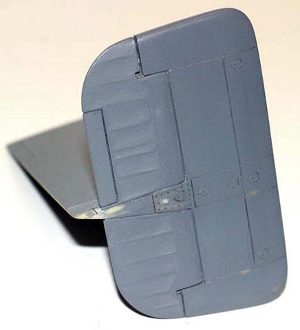
The rudders were then sprayed with grey primer and the metal areas
polished. The fabric areas were polished less so that a difference in
texture can be seen. The tailplanes and elevators were done in much the
same way apart from the fabric covered elevators. These do not show any
sagging between the ribs. The elevators are almost totally flat with
only the metal rib tapes visible. To simulate these grey primer was
sprayed on to decal film and thin strips cut out and applied.
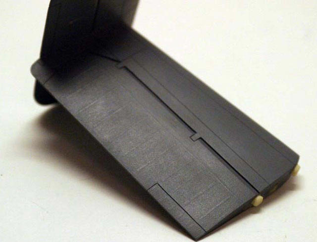
Once over sprayed with primer these sections were again worked so
that the difference in texture is just visible.
Further interior detailing
Work continued on the two fuselage half interiors.
The flare chute was replaced with a more accurate version, not that
any one will be able to see it once the halves are together. The area
behind the Flight Engineers section is mostly complete now and as we
move into areas that will actually be seen the level of detail will move
up a degree. This means that I am going to have to do some etchings. The
problem with this is that if you want to get them done professionally
then you need artwork for pieces that are some way ahead of where you
actually are. The first part that I etched at home was a gate for 6
levers in the F.Es station. This was done by cutting out a small piece
of brass slightly larger and twice as thick as the part required. One
side was coloured with a permanent marker and allowed to dry. Apply
black to the front face only. As the acid etches from the back it
reduces the thickness by half. This way you do not need to register the
design on the back face only the front. The areas that needed to be
removed were then scratched into the black using a needle in a pin vice
and a magnifier. This was tricky as the part is actual size (5mm x 3mm
with six slots in it) and it took a few attempts to get it right .The
part was then dipped into the etching liquid and agitated for about
10-15 mins . Once washed off the part was cleaned up and a reasonable
part had been made. You cannot get the detail or finesse of parts made
from photo reduced artwork but for the simpler parts it works fine. I
was going to produce artwork on my computer but it was taking to long
(not that good with computers) so I am doing them the old fashioned way
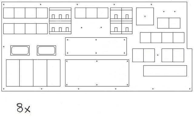
by drawing them out at 8x size and pasting to form a piece of A1
artwork.
Simple rules are; Black (nothing removed either side) Red (half etch
front face) Blue (half etch rear face) white (etch through both sides).
Then find out your minimum line thickness for the drawing which would
typically be 8x the thickness of the brass being etched, so on 10 thou
brass the min line thickness on the artwork should be 80 thou. Red/blue
areas should be all colour with no black outline.
I find it easiest to cut parts out of coloured paper and paste them
into the main page. Once your artwork is done a reduced photo
negative/positive (cannot remember which) is made and the sheets etched.
Remember also that when drawing components like instrument bezels to
actual 1/48 size that it can mean that they will not fit into the space
on the panel. The panel itself WILL be undersize because of the
thickness of the fuselage sides not being scale thickness; this also
applies to your injection kits. This is where true scale goes out of the
window and it becomes a matter of finding the proportions of each piece
within a certain space.
Shown above is a first try at producing a basic layout for the F.E
panel drawn in MS paint
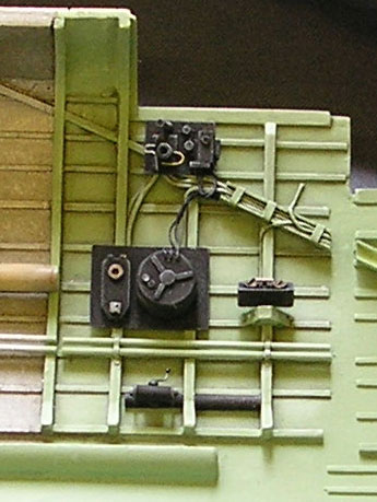
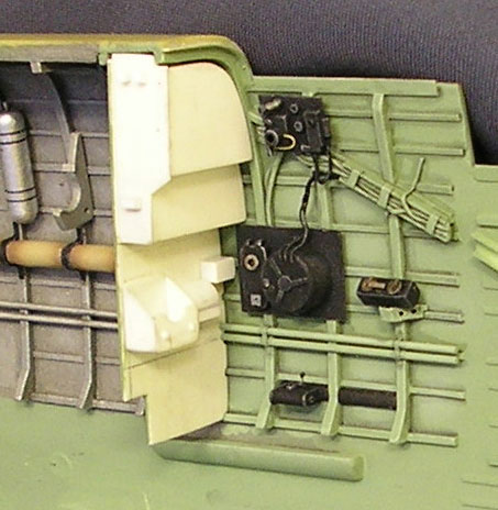
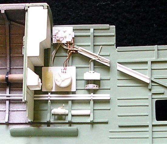
The next series of pictures shows work progressing into the F.E’s
station. Lots of head scratching as there were a couple of spots I did
not have covered by photos. In the end it came out okay.
The wiring is a mix of Miliput, lead wire and copper wire. Miliput is
ace it lays really naturally in a way that I find that I cannot get in
copper. Lead is somewhere between the two in terms of ease of use. You
can get the lead and copper wire from fly fishing shops. Get the lead
wire its good! One great property of the Milliput is that you can roll
it to the very diameter that you need, useful as in the photos below I
had to get a certain number of wires into a set space.
It can be very carefully applied soon after rolling or left for 20 –
30 mins to stiffen up a little. The detail parts below are made in the
usual way from evergreen plastic rod/strip etc.
Click the thumbnails below
to view larger images:
Next, the bulkhead between the pilot and flight engineer was detailed
with some rivet detail and plastic strip.
After this, a start was made on the pilots seat. I found some great
pictures of a pilots seat that has been rebuilt. Thankfully one of these
was a straight on side view. After a whole evening of gazing at the
pictures I figured out how to make it. Using tracing paper the outline
of the side plates was drawn. I knew what size that I needed the seat to
be so I worked out the ratio that I would need to reduce it by. I
scanned the drawing, reduced and then printed it out using my copier.
Once done a template was made and the two sides cut out of plastic card.
For the seat pan a small master was made and a plunge moulded again in
plastic card. With the seat pan and sides joined together the front and
rear plates were added. For the beading around the seat pan plastic rod
was used for the straight sections and lead wire for the semi circular
cut out at the front.
Next to be added will be the tubular support for the backrest, the
backrest itself and the harness and attachment points.
Next time...
More progress on the floor insert and pilots area
Model, Images and Text Copyright ©
2005 by Philip Robson
Page Created 29 April, 2005
Last Updated
29 April, 2005
Back to
HyperScale Main Page
|
 Home
| What's New |
Features |
Gallery |
Reviews |
Reference |
Forum |
Search
Home
| What's New |
Features |
Gallery |
Reviews |
Reference |
Forum |
Search