|
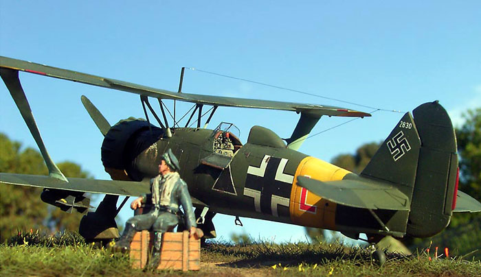
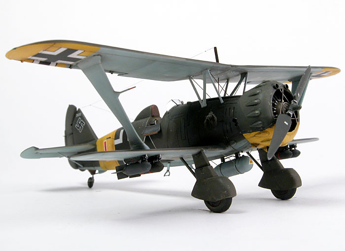
Detailing the
Airfix 1/72 scale
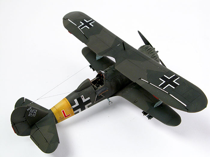
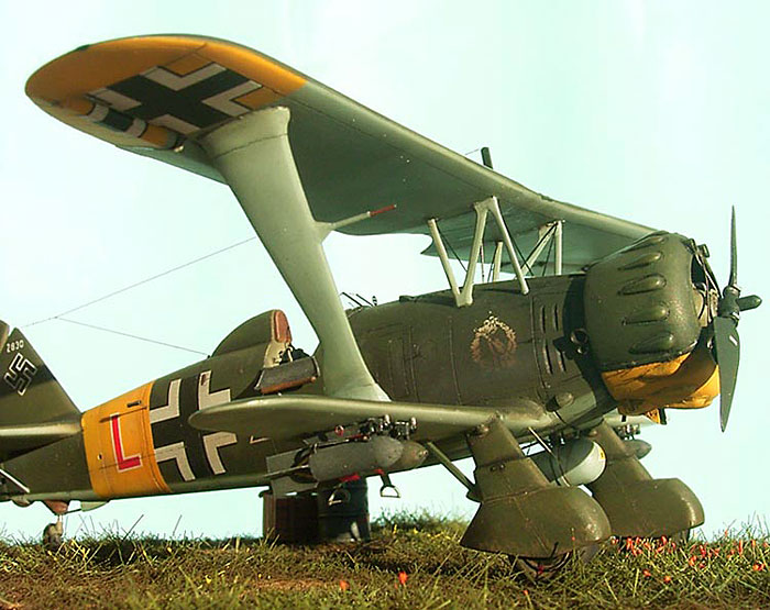
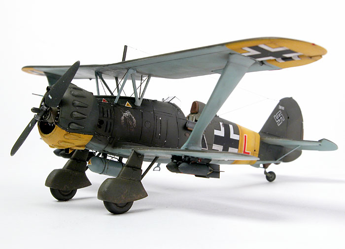
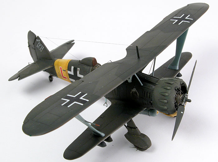
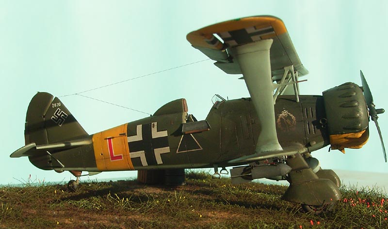
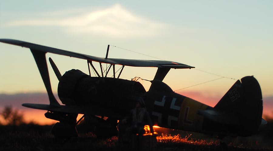
Henschel Hs 123B
by Glenn Irvine
|
 |
|
Henschel Hs 123B |

Airfix's
1/72 scale Henschel Hs 123 is available online from Squadron
The Henschel 123 was a 1930’s design that was
relegated to second line duties fairly early in its life due to advances
in aeronautical design, but as history would show, was later to achieve
much greater success in its field due to its basic and rugged design
than it’s much more modern replacements which struggled when the
conditions were too harsh for their finicky design.
The Russian front during the extremes of climate
change is no place for wimps or finicky highly strung engineering
designs. Unfortunately the German war machine was filled with such
‘wunder weapons’ and as impressive as they were to the rest of the
world, they had not factored in the extremes of the environments they
would be asked to operate in. This blinkered approach would eventually
be part of the great undoing of the Third Reich’s vast war machine.
To give an example of the simplest of problems that
happened in winter in Russia was the problem of finding the round would
not fit in the chamber of your rifle due to such extreme contraction of
the metal in the cold and the very fine machining tolerances commonly
used by the German manufacturing industry. The Russian machinery on the
other hand was a lot cruder, but, it did continue to function even under
the most extreme of climatic conditions.
The Henschel was an example of the latter and as
such was able to function when a lot of the other war machinery would
not. It was basic in design and thus, easy to maintain, easy to fly and
much loved by its pilots. The aircraft soldiered on until there were
none left. At one point an attempt was made to put it back into
production, such was it’s effectiveness, unfortunately this was not
possible as the jigs had been destroyed long before as more modern
machinery succeeded it.
The Kit - Airfix 1/72 scale Hs 123B-2
This was one of Airfix’s early bagged release kits,
and I remember building it for the first time in the early 70’s. As a
kit it is typical of the time, fairly basic components, crude detail by
today’s standards and not particularly accurate. Unfortunately it is the
only game in town. It represents an early A series airframe with the
fabric wing and the later headrest fairing as found on the B series.
Preparation
I wanted to build the B series which had the wing
fully skinned in metal so I had to do a lot of sanding first.
Fortunately there is a lot of excess plastic built into the kit. The
first thing I did was attack the flying surfaces with a small bastard
file to bring the wing back to something approaching an aerofoil shape
then finish of with successive grades of sanding stick. After this, the
entire airframe was rescribed using the plans in the Wydawnicto book as
my primary reference with extra detail added after detailed examination
of available photographs.
Construction
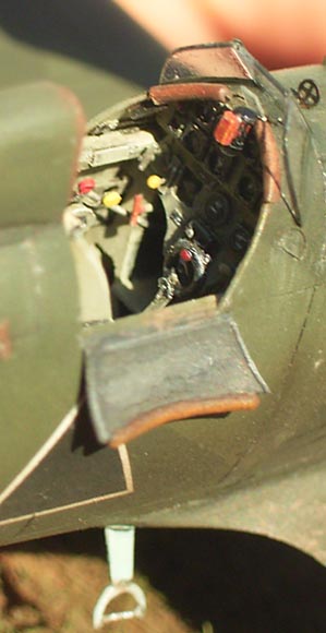
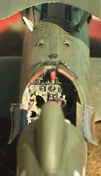
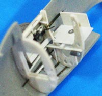
The fuselage came in for some extra detailing and
accurizing as well. The cockpit was entirely scratchbuilt using drawings
and photos as reference. Some of these drawings came from Modeldad,
thanks! , also reference was made to the 1/48 resin set in the AML kit,
photos of these are found in one of Hyperscales reviews. The fuselage
was thinned down to paper thin with my Dremel and bulkheads and
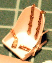
stringers were fabricated. The seat was plunge formed out of a coffee
sipper lid! These are great for those little plunge form jobs like this
as they have a stiffening rim which gives you something to hold it with
and to support the softened plastic while you plunge your master into
it. I use a small candle to apply heat. They are made from about 8-10
thou sheet so are perfect for this sort of work and, best of all, they
are free!!
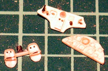
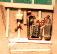
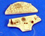
The instrument panel, side consoles, throttle
quadrant, radio boxes and oxygen regulator and bottle was built up using
sheet styrene and stretched sprue, plus the odd leftover etched metal
part as lever handles with white glue as the knobs. Seat belts were
etched metal from an Airwaves set for the shoulder harnesses and foil,
tape and wire for the lap belts.
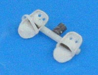 The
rudder pedals were plunge moulded and drilled to represent the early
style pedals that were in use at the time the Henschel was built. The
control column was built up from strip and wire and includes the brake
lever and the gun firing button. The oxygen hose was from fine wound
guitar string. The side access doors were cut out and masters made to
plunge mould new ones of the correct shape, padding was added from fine
lead wire. This was also added to the forward cockpit edge either side
of the gunsight. The
rudder pedals were plunge moulded and drilled to represent the early
style pedals that were in use at the time the Henschel was built. The
control column was built up from strip and wire and includes the brake
lever and the gun firing button. The oxygen hose was from fine wound
guitar string. The side access doors were cut out and masters made to
plunge mould new ones of the correct shape, padding was added from fine
lead wire. This was also added to the forward cockpit edge either side
of the gunsight.
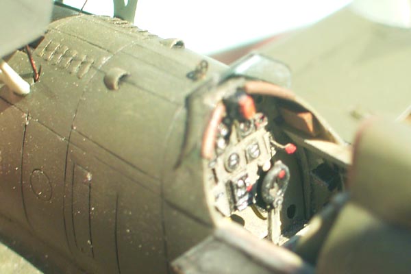
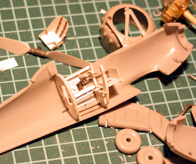
 Now
for the main fuselage, for a start, the headrest fairing had to be
reshaped and shortened and a new headrest pad made from plastic sheet,
the forward fuselage was circular in cross section and this was
incorrect as the cowling complete with exhausts would not fit. So, after
analysis of photos it was found that the fuselage was actually oval in
cross section and this allowed the exhausts to fit. The upper gun
decking was attended to at this point too, as it was very crude and
required the gun ventilation louvers to be entirely redone out of 5 thou
card embossed with louvers of the appropriate size. These panels were
then fitted to areas that were slightly recessed with my Dremel. After
gluing they were blended in with filler. The upper gun decking did not
match the curvature of the lower forward fuselage at this point and was
blended in with super glue. Provision was made to fit gun barrels later
so stops were glued in just aft of the gun openings. New reversed vent
scoops were made and glued in place behind the louvers. Now
for the main fuselage, for a start, the headrest fairing had to be
reshaped and shortened and a new headrest pad made from plastic sheet,
the forward fuselage was circular in cross section and this was
incorrect as the cowling complete with exhausts would not fit. So, after
analysis of photos it was found that the fuselage was actually oval in
cross section and this allowed the exhausts to fit. The upper gun
decking was attended to at this point too, as it was very crude and
required the gun ventilation louvers to be entirely redone out of 5 thou
card embossed with louvers of the appropriate size. These panels were
then fitted to areas that were slightly recessed with my Dremel. After
gluing they were blended in with filler. The upper gun decking did not
match the curvature of the lower forward fuselage at this point and was
blended in with super glue. Provision was made to fit gun barrels later
so stops were glued in just aft of the gun openings. New reversed vent
scoops were made and glued in place behind the louvers.
The large engine cooling louvers on either side of
the forward fuselage were cut in and shaped as they were gone completely
after reshaping the forward fuselage, not that they were there in the
first place, at least not properly.
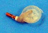
The engine in the kit was a complete waste of time
as supplied from the kit and I had to find a replacement, so, after
looking in my kit stash, I found I had nothing that would work, so, what
does a resourceful modeler do? Why raid a friend’s stash that’s what!!
After looking in Lawrence’s stash I found an engine
from the Hasegawa 1/72 Buffalo which filled the bill nicely. I took this
part home and made a silicone rubber mould of it and cast it in resin
twice.
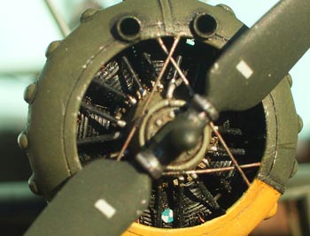
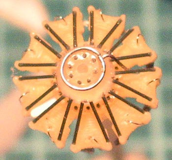 I
only cast the rear face as the front face had pushrods moulded onto it
and I did not want that as I was going to replace all that with
stretched sprue. So, there I was with two copies which I then sanded
back till they were each half thickness, I then glued them together as
perfectly aligned as I could. Sprue pushrods were added and the ignition
wiring, the reduction gearcasing was turned up on my dremel from some
thick acrylic rod. This had holes drilled to take stretched sprue as
bolt heads and lead wire for the oil pipes and the forward rim of the
casing. This land would later be the location for the cowling bracing
wires so evident in photos of the real aircraft. I also added a shim of
rod on the oil sump painted as the BMW logo which is often very visible
on their radial engines I
only cast the rear face as the front face had pushrods moulded onto it
and I did not want that as I was going to replace all that with
stretched sprue. So, there I was with two copies which I then sanded
back till they were each half thickness, I then glued them together as
perfectly aligned as I could. Sprue pushrods were added and the ignition
wiring, the reduction gearcasing was turned up on my dremel from some
thick acrylic rod. This had holes drilled to take stretched sprue as
bolt heads and lead wire for the oil pipes and the forward rim of the
casing. This land would later be the location for the cowling bracing
wires so evident in photos of the real aircraft. I also added a shim of
rod on the oil sump painted as the BMW logo which is often very visible
on their radial engines
The rear of the engine had the exhaust manifold
constructed from solder of various thicknesses and the exhaust outlets
were made from heat formed rod that had been hollowed out with the
dremel tool. All this would be invisible once the cowling was fitted to
the fuselage but it made me feel better that I had built it as it was
quite a bit stronger and ………just because …OK. To tell you the truth I
had planned to open up one of the forward fuselage panels and the lower
cowl on one side, but could not find enough info on what this area would
have looked like, so did not go ahead with it.
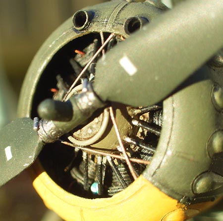
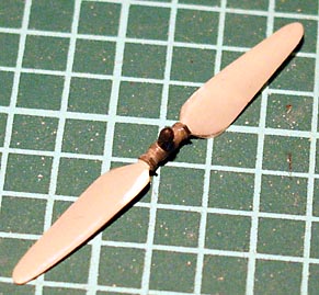 The
propeller was thinned down to more scale like aerofoil thickness and the
hub scratch built from tube, rod and sprue. This was a complete pain as
it broke in the middle of the blades several times as it was so thin,
however MEK to the rescue. I don’t use this stuff all the time, but, it
is good for really quick solid joins with very little excess melting of
the parts. The
propeller was thinned down to more scale like aerofoil thickness and the
hub scratch built from tube, rod and sprue. This was a complete pain as
it broke in the middle of the blades several times as it was so thin,
however MEK to the rescue. I don’t use this stuff all the time, but, it
is good for really quick solid joins with very little excess melting of
the parts.
The cowling was cleaned up and the lower induction
scoop and oil cooler cover was shaped from plastic stock and attached
including the drain tube and starter crank hole. The interior was
thinned down extensively to fit the new engine in and to look more to
scale. The gun blast tubes were made from plastic tubing and thinned
down on the ends; these were fitted to holes drilled in the cowling.
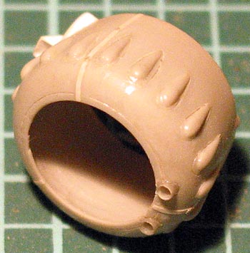 The
cowling joint stiffeners were replicated with strips of stretched sheet
styrene to get extra thin strip and the cowl was scribed. The
cowling joint stiffeners were replicated with strips of stretched sheet
styrene to get extra thin strip and the cowl was scribed.
The tail wheel was scratch built as the kit one was
totally useless, so a wheel was turned up from acrylic rod and a yoke
made from plastic scrap and the leg from wire. The canvas/leather boot
was shaped from plastic scrap and glued in place. The tail wheel drag
strut shroud was also hollowed out and the drag strut made from
stretched sprue. The rear bump stop was built up from scrap plastic
super glued in place. This tail wheel area was misshaped and suffered
from sink marks so was built-up with putty before replacing all the
detail.
The main wheels were undersized, so spare wheels
from the ‘thou shalt not throw anything kit related away collection’
were put to good use. (no, I don’t know what they came off, they just
measured up to the correct scale size). The main wheel covers had some
sinkmarks and were filled, scribed and extra detailing added, they were
also hollowed out with the ….you guessed it! Dremel tool. The support
struts to the rear of the covers were thinned down to aerofoil shape as
well.
The flying surfaces were all removed and hinge
detail added. At this time Mr Surfacer 500 was brushed on with a 000
brush in fine lines that were tidied up after drying to replicate the
stitching on the fabric covered structure. The ailerons posed a special
problem as they had an unusual shape and no drawing or photograph showed
clearly how the hinges were aligned or how it worked. The underside of
the wing had a 45 Degree angle back to the top surface of the wing which
closely matched the aileron, so there was a large gap between the lower
surface of the wing and the forward edge of the aileron. This design is
consistent with a Friese type aileron but the leading edge of this type
usually has a forward edge on the lower surface further forward than the
top surface. This means that with the hinge placement on the lower
surface of the aileron and level with the top surface joint with the
wing, when the aileron is tipped up a large gap forms between the
ailerons lower forward edge and the lower wing surface and this projects
into the airflow causing drag which helps assist further deflection.
Such seemed not quite the case with the ailerons on
the Henschel. As I couldn’t work out exactly how the whole thing was
designed, I compromised as best I could. – I think it looks OK and I
think I got it nearly right.
I wrote this to illustrate how I went about
detailing this area and the kind of understanding of the mechanical
design sometimes needed to determine the detail required in an area not
sufficiently covered by references.
The interplane struts were thinned down to scale
thickness and the cuffs were simulated with a layer of Mr Surfacer 500
painted on and sanded lightly. The pitot tube was added from fine steel
wire sheathed in stretched tube and faired in with plastic and
superglue. The other struts were thinned down to scale as well, they had
been removed from the fuselage complete and had to be carefully refitted
to the fuselage after fitting the top wing as they were glued to it
first, as were the interplane struts.
When the upper wing was sanded to shape a thinner
section was sanded in the center section as the real aircraft had. I
then had to add a strip of baremetal foil in the centre to simulate the
jointing section in the middle of the wing. Navigation lights were made
from krystal kleer over painted with transparent red and blue/green.
The horizontal tail planes were separated and hinge
detail added. The rear edges were recessed and the trim tab actuators
added. The support struts were added from stretched plastic strut stock
and the joint to the fuselage faired with super glue.
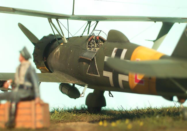
The kicksteps were made from wire, sprue and sheet.
The drop tank was turned up from plastic stock and all connector’s hoses
and the rack were made from wire and plastic. The bomb racks were made
from strip, sheet and wire. The forward braces were a complicated shape
difficult to replicate individually in this scale until I realized that
making a length of ‘stock’ material of a cross section of the same shape
as the aforementioned forward braces, I could, when dry, simply slice
off sections of the correct thickness to replicate each brace and glue
these in place. Amazing what comes to you at 3 in the morning!
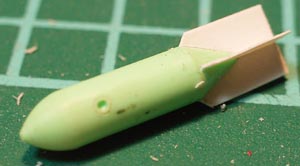
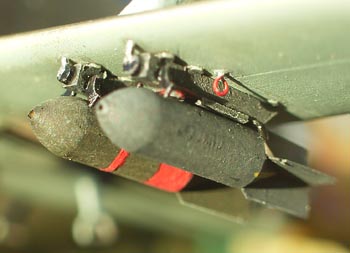 The
bombs were junk and I built a new one of accurate size and shape, but
had such fun with the 5 thou fins individually glued in place and
aligned, I decided to cast this bomb in resin and save myself the
stress. The
bombs were junk and I built a new one of accurate size and shape, but
had such fun with the 5 thou fins individually glued in place and
aligned, I decided to cast this bomb in resin and save myself the
stress.
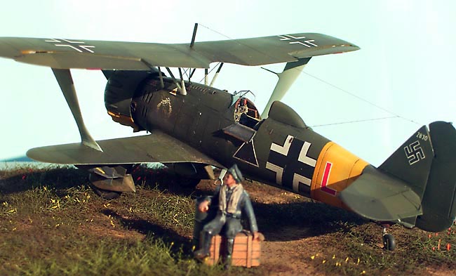
The side pitot tube was made from stretched tube
and fine wire and mounted the very last thing. The aerial was made from
synthetic stretchy transparent material coloured with a permanent
marker, I suspect is knitting elastic or lycra, anyway it is incredibly
fine, very hard to break and stays taut.
|
 Home
| What's New |
Features |
Gallery |
Reviews |
Reference |
Forum |
Search
Home
| What's New |
Features |
Gallery |
Reviews |
Reference |
Forum |
Search