|
Pacific Coast Models'
1/32 scale
Macchi C.202
Folgore
by
Ian Robertson
|
 |
|
Macchi C.202 |

HyperScale is proudly supported by Squadron.com
Background
The C.202 Folgore was one of the best Italian
aircraft of WWII, proving itself in the Mediterranean theater as a
formidable adversary for the Hawker Hurricane, P-40 Tomahawk, and early
Spitfires. A direct descendent of the C.200 Saetta, the C.202 Folgore
had a smaller fuselage cross section, enclosed cockpit and retractable
tail wheel. Most importantly, the forward fuselage was redesigned to
accept a DB.601 inline engine, giving the C.202 it’s sleek and fearsome
appearance. The C.202 retained the C.200’s asymmetric wing length to
compensate for engine torque rotation.
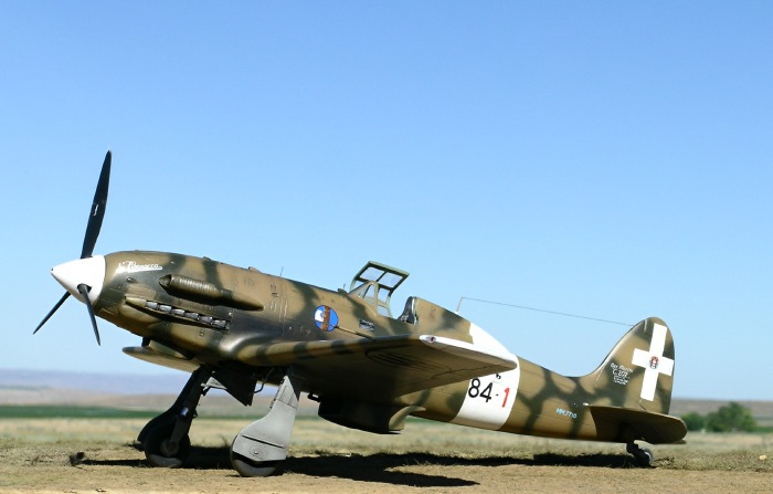
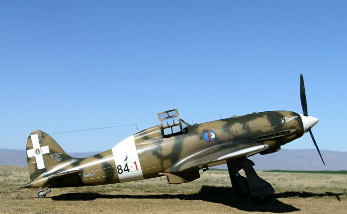
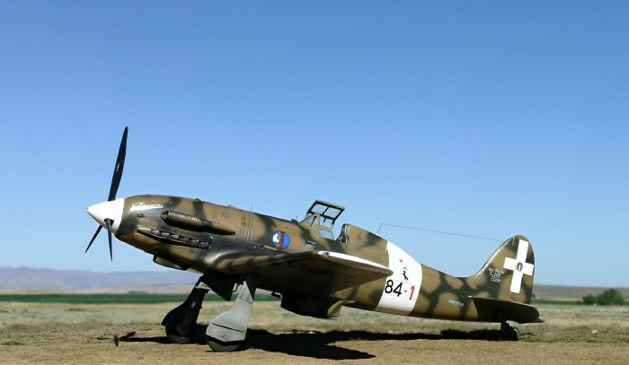
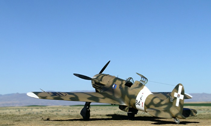
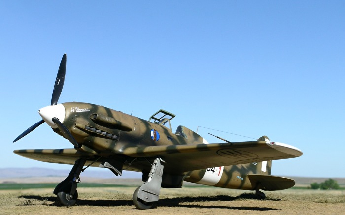
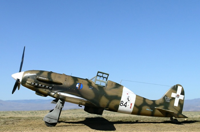
Here I present Pacific Coast Models’ 1/32 scale C.202 Folgore as a
series III aircraft flown by Capt. Franco Lucchini, commander of 84a
Squadriglia, 10th Stormo, fall 1942.
Photographs of Capt. Lucchini’s aircraft (see pg 61
in Osprey’s “Italian Aces of WWII”) show a replacement starboard wing
and a replacement panel on the cowl. For variety, I chose to depict
Lucchini’s aircraft prior to these field repairs.
PCM’s kit – what’s in the box?
Like the C.200 kit before it, PCM’s C.202 is an
excellent example of just how far short-run kits have come in recent
years. The grey styrene parts, manufactured by MPM, feature finely
recessed panel lines and plenty of detail. The plastic is a bit softer
than what you get in a Tamiya or Hasegawa kit, but it remains easy to
work with. A number of panel lines on my kit were partially filled,
requiring rescribing. Some large ejection stubs in the inside surfaces
of the fuselage and wings required removal, but this was not
problematic.
The canopy is injection molded with well defined framing.
The resin parts are excellently crafted and include a well detailed
cockpit, radiator, and lower cowl. The kit also includes a large fret of
Eduard photoetch. In general, the photoetch parts are reserved for those
places on the model that really benefit from them (e.g., the seat
harness, instrument panel, radiator grills). I left off some of the more
fiddly pieces of photoetch, choosing instead to fashion my own details
from other materials.
Decals were produced by Sky Models and printed by Cartograf. Seven
attractive marking options are provided, spanning a wide range of
camouflage styles for the C.202.

It is clear that PCM has attempted to “stretch” the molds of their C.202
kit by including details found on C.205s. This makes perfect sense given
that a 1/32 C.205 has been announced as the next kit for release by this
company. Some simple modifications are therefore required to build an
accurate C.202, although these modifications are not mentioned in the
instructions.
I will start by emphasizing that this is an
excellent kit and I thoroughly enjoyed building it. It is a great
example of just how good a limited run kit can be, and how subjects that
many doubted would ever be produced in injection molding are now getting
a chance to shine in 1/32 scale. While this kit is definitely not
intended for beginners, it should be well within the reach of modelers
with moderate experience, particularly those with experience using resin
and photoetch. I found the C.202 comparable in difficulty to the Pacific
Coast Models 1/32 C.200 and Azur 1/32 D.520.
Cockpit
Construction begins with the resin/styrene/photoetch
cockpit. The parts are finely detailed and fit together quite well,
although the assembly is not without challenges owing to the fiddly
nature of the small parts. Translation - I’m all thumbs when it comes to
photoetch.
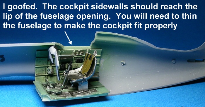
A more significant difficulty I had with the cockpit was determining how
far down in the fuselage it should sit. The correct answer is that the
top of the resin side walls should reach the lip of the cockpit opening
on the fuselage (sigh…..just as it is shown in the instructions).
However, if you do not thin the sidewalls of the fuselage prior to
installing the cockpit, the cockpit will sit 1-2 mm too low when the
fuselage halves are attached. This is what happened on my model, and I
did not realize my mistake until after the cockpit was installed and the
fuselage halves were attached. What gave away my error? When I tried to
install the photoetch seat harness the strap was not long enough to
mount on the plate behind the pilot’s head. To overcome this problem I
scratch built a slightly larger harness from lead foil and incorporated
the original photoetch chains and buckles.
Despite my mistake, the cockpit tub looks great when finished and
installed in the fuselage. However, little did I know that my gaff
created another problem that would appear in the next phase of
construction!
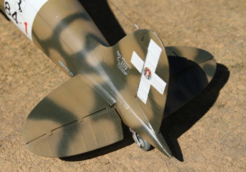
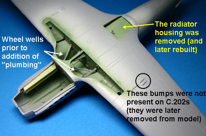
Wings
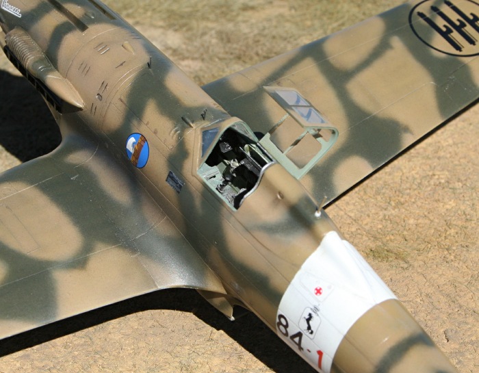
The error I made in positioning the cockpit
returned to haunt me when I tried attaching the wings to the fuselage.
Specifically, the radiator housing that is molded on the interior of the
lower wing bumped the underside of the cockpit, preventing attachment of
the wing. My only option was to remove this radiator housing from the
wing (see photo), attach the lower wing to the model, and then rebuild
the housing from sheet styrene. As luck would have it, the underside of
the cockpit was the perfect depth to accept the radiator screens, and
the resin radiator fit perfectly over top. I dodged a bullet!
Wing dihedral and alignment was perfect, and the upper sections of each
wing fit without difficulty once the lower wing was in place (I
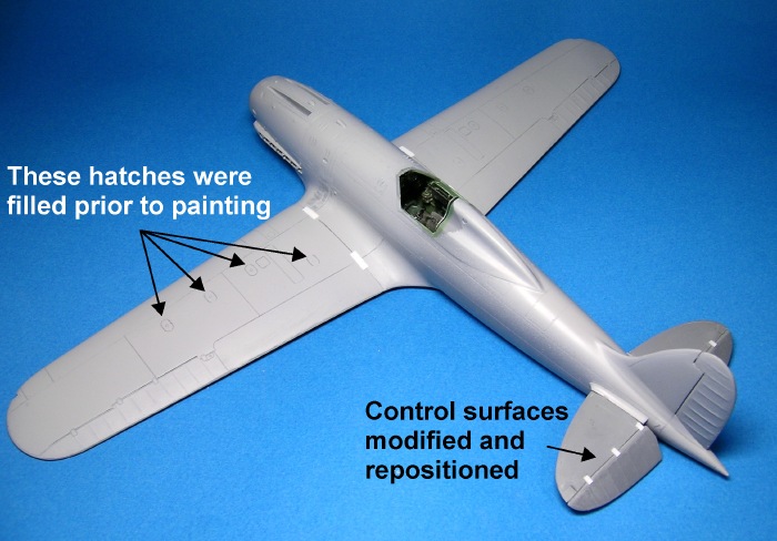
carefully dry-fitted these parts prior to gluing). Be sure to thin the
trailing edges of the wing before gluing. Also, the four round hatches
on each wing were filled because these were specific to C.205s. The
bumps on the underside of the wing were removed for the same reason.
Even though the aircraft I was modeling probably lacked wing guns (most
series III aircraft did), I left the rectangular access panels for the
guns in place. According to Maurizio Di Terlizzi (in Aviolibri’s “Macchi
MC202 Folgore, Pt 1a”), series III aircraft were upgraded with wing guns
(and thus had the access panels), although in most cases the guns were
later removed and the holes plated over.
Wheel Wells
The wheel well is an area on the model that begs
for detail in the form of wires and hoses.
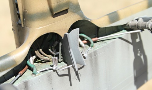
I referred to color photos in the Mushroom Models
book “Macchi C.202 Folgore” and used solder wire to simulate the
plumbing.
Horizontal Stabilizers
The kit provides elevators suitable for C.205s and
C.202 series XI-XIII. If you want to build a C.202 series I-X, you will
need to modify the elevators as shown in the photo below.
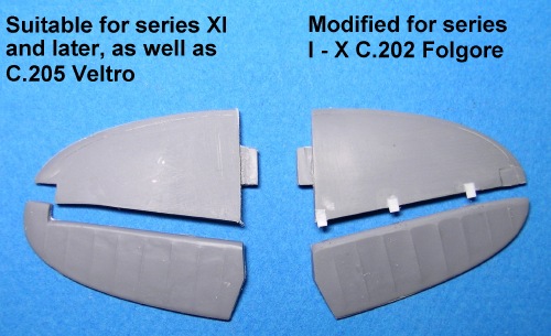
To make the modification, simply clip the balance
off the tip of the elevator and reattach it to the main part of the
stabilizer using CA glue.
The Nose
Some concern has been raised regarding the fit, as
well as shape and size, of the C.202’s spinner. There is definitely a
problem to solve because the spinner plate is considerably smaller in
diameter than the tip of the cowl. My impression is that the cowl
doesn’t curve inward sufficiently at the tip, resulting in an anterior
cowl diameter that is larger than the spinner plate. I therefore
reshaped the cowl with sand paper until it was the same diameter as the
spinner. To me the nose and spinner look just fine following this simple
modification; however, I did not go to the trouble of measuring the
spinner for accuracy. Should the spinner turn out to be the problem, a
more elaborate fix will be required.
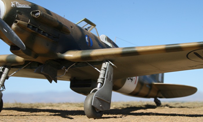
Landing Gear
The final major step in construction was attaching
the landing gear. I experienced some difficulty achieving proper forward
rake for the struts. Based on photographs and color profiles, the rear
edge of the gear covers should be close to square with the lower wing.
However, my initial attempts at fitting the struts in their sockets left
the undercarriage too upright, causing the nose to sit too high and the
model to look “off”.
I made a few adjustments to the socket and finally
got the struts to rake properly forward. It made all the difference in
the world to the appearance of the model.
Paint
 The cockpit side walls were painted in Polly Scale
RAF interior green (a reasonable match for Italian cockpit green) and
then treated with washes and chalk pastels. The seat, control stick, and
plate behind the pilot were painted in Alclad II duraluminum and then
treated with a thin black wash (Tamiya acrylic). The cockpit side walls were painted in Polly Scale
RAF interior green (a reasonable match for Italian cockpit green) and
then treated with washes and chalk pastels. The seat, control stick, and
plate behind the pilot were painted in Alclad II duraluminum and then
treated with a thin black wash (Tamiya acrylic).
The exterior of the model was primed with Tamiya fine grey surface
primer and then polished lightly with a micromesh sanding cloth. The
fuselage band, wing tips, and tail cross were sprayed white and masked
for the remainder of the painting.
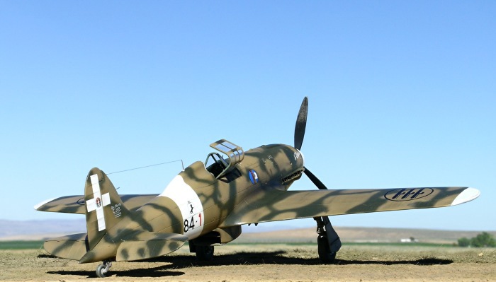
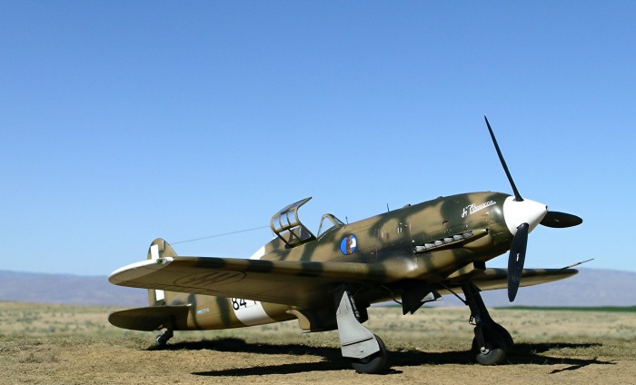
The underside of the model was painted Polly Scale Italian Light
Blue-grey. The wheel wells were painted interior green. For the upper
surfaces I mixed my own version of Nicciola Chiarro (hazelnut tan) using
a 50/50 mixture of Aeromaster RLM79 and Polly Scale Israeli Khaki. Once
the Nicciola Chiarro mix had dried I applied dark green patches freehand
using Polly Scale Italian Olive.
The propeller blades were first painted Alclad II duraluminum followed
by scale black. Wear was simulated by wet sanding the rear tips of the
propeller blades with a micromesh sanding cloth.
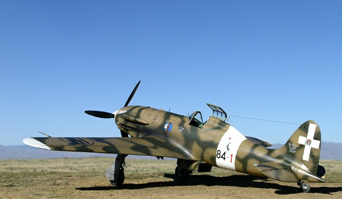
Decals
The decals for this kit worked beautifully.
Although the scheme I chose was not one of those indicated on the decal
sheet, most of the markings I needed were present. The kit decals even
included the “84 -“ I needed (I had a suitable red “1” among my spares),
but from photos it was apparent that the size and thickness of these
numbers was incorrect for Lucchini’s aircraft. Therefore, I made my own
decals for the “84 - 1” on each side of the fuselage. The markings were
printed on Testors decal paper using a Hewlitt-Packard deskjet printer.
Once dry, the decals were coated with fine mists of Testors decal bonder
(clear lacquer in a rattle can), allowed to dry overnight, and then
applied to the model as per usual.
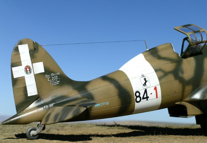
Photographs indicate that the symbol typically seen
in the center of the tail cross on Italian aircraft was absent from this
aircraft. I opted to add the symbol on my model any way.
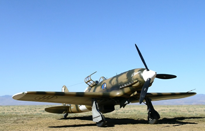
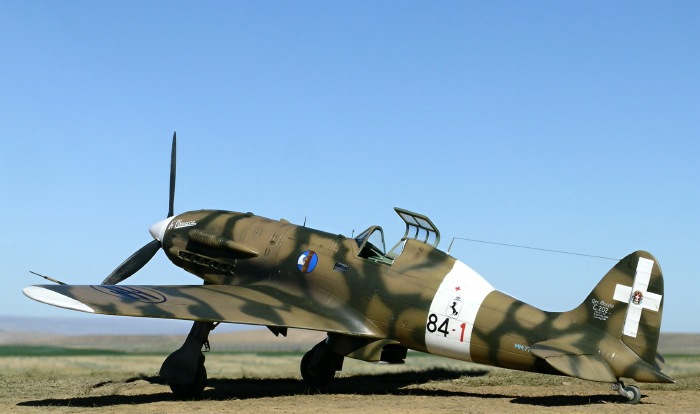
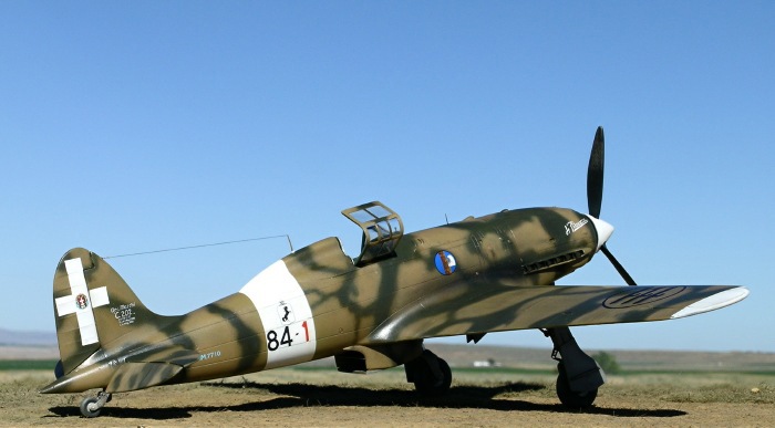
Images of the completed model were taken outdoors
in natural light with a Nikon Coolpix 5400 digital camera. The “unsharp
mask” tool of Adobe Photoshop was used to restore some of the clarity
and crispness lost during image compression. The mountains in the
background are the Owyhees in south-western Idaho.
Pacific Coast Models has added another winner to
their growing 1/32 lineup. Based on the same basic design as the 1/32
C.200 kit, the C.202 is somewhat easier to build because of the inline
engine.
For my money this kit is well worth the price given
the good fit, detailed resin parts, photoetch, and marking options. I’ll
be keeping my eyes (and wallet) open for the PCM 1/32 C.205 Veltro down
the line!
Click on the thumbnails
below to view larger images:
Italian Aces of World War
2
Aircraft of the Aces 34 |
|
|
|
|
Author: Giorgio Apostolo
Illustrator: Richard Caruana
US Price: $19.95
UK Price: £12.99
Publisher:
Osprey Publishing
Publish Date:
November 25, 2000
Details: 96 pages; ISBN: 1841760781 |
|
|
Model, Images and Text Copyright ©
2006 by Ian Robertson
Page Created 17 July, 2006
Last Updated 19 July, 2006
Back to HyperScale
Main Page
|
 Home
| What's New |
Features |
Gallery |
Reviews |
Reference |
Forum |
Search
Home
| What's New |
Features |
Gallery |
Reviews |
Reference |
Forum |
Search