|
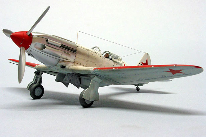
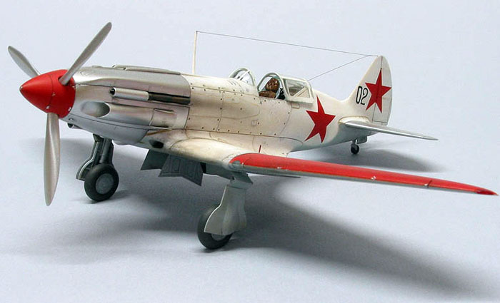
MiG-3
by
Tony
Bell
 |
|
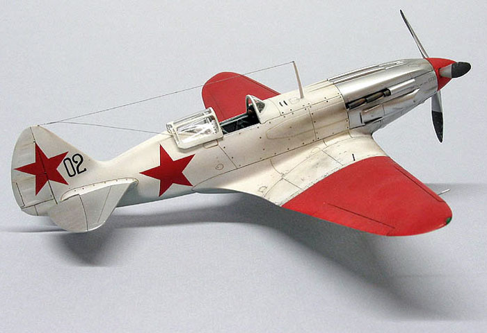
MiG-3 |

ICM's 1/48 scale
MiG-3 is available online from Squadron.com
In early 1939 the Voyenno Vozdushnyye Sily, (VVS – the Soviet
Air Force) issued a requirement for a high altitude strategic interceptor, which
the Polikarpov design bureau was assigned to develop. Polikarpov fell out of
favour with Stalin however, and the new MiG design bureau headed by Artem
Ivanovich Mikoyan and Mikhail Iosifevich Gurevich was given the task instead.
The resultant I-200 was a small fighter built around the powerful but heavy
AM-35A engine. The aircraft was very fast (651 kph) but extremely difficult to
fly because of poor longitudinal (pitch) stability due to the short rear
fuselage. In spite of handling problems and short range, the I-200 was ordered
into production as the MiG-1.
The MiG-3 was a result of an attempt to rectify the MiG-1’s range and stability
shortcomings. Stability was improved by increasing the wing dihedral and
lengthening the nose to move the centre of gravity forward. The aerodynamics
were cleaned up, and pilot’s armour and an additional fuel tank added. These
changes improved the flight characteristics from “extremely difficult” to merely
“difficult”.
The MiG-3 was produced starting in late 1940, and constituted close to 90% of
the modern VVS fighter force at the time of Operation Barbarossa in June 1941.
The air war over the eastern front was more tactical than strategic in nature,
with most combat taking place at altitudes of 5000m or below. With an engine
optimized for performance at an altitude of 6000m, it quickly became apparent
that the MiG-3 was outclassed by the Luftwaffe opposition at lower altitudes. In
the first half of 1942 it was withdrawn from the front line to serve in air
defence squadrons for the remainder of the war.
The MiG-3’s AM-35A engine was produced in the same factory as its closely
related cousin, the AM-38 which powered the Ilyushin IL-2 Sturmovik. Stalin had
declared that the Sturmovik was “as important for the Red Army as air and bread”
and production of the AM-35A was discontinued in favour of the AM-38. Although a
MiG-3 fitted with an AM-38 exhibited improved performance, the AM-38 was
reserved exclusively for the IL-2. Production of the MiG-3 ceased in December
1941.
The ICM MiG-3 comes packed in a flimsy, end opening box (grrrrr!).
The kit consists of five sprues in light grey styrene and one clear. The clear
parts are quite transparent, if not a little on the thick side, and the grey
plastic parts have a fine pebbly texture and nicely engraved panel lines,
although the fabric texture on the control surfaces is way overdone. The parts
also sport a heavy coating of mould release grease, necessitating a good scrub
with dish detergent and an old toothbrush. The kit includes a very complete
looking AM-35A engine which is a separate model in its own right.
Some of the thicker parts exhibit sink marks, most notably the propeller blades,
main wheels and horizontal stabilisers. The decals are very thin and matt, not
unlike Italeri kit decals. They suck, frankly. They are translucent and
delicate, and broke into pieces as soon as I tried to shift them from the
backing paper. As far as marking options go, the kit that I bought was the
boxing which only includes markings for VVS ace and Hero of the Soviet Union
Nikolay Krasnov. The other release of this kit includes markings for 10 aircraft
in a variety of different winter and summer schemes.
The MiG-3 is not a simple aircraft, with numerous scoops, intakes, lumps and
bumps. The parts breakdown is likewise complicated, but necessary to avoid
compromising detail.
Given the complicated nature of the kit, it would be wise to
follow the instructions which would have you start construction with the engine.
However, having read several reviews of the kit I opted to avoid any potential
fit issues I the construction of the nose and omit the engine. For me,
construction therefore started with, you guessed it, the cockpit.
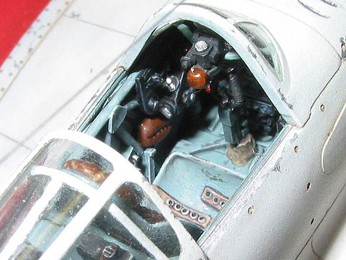
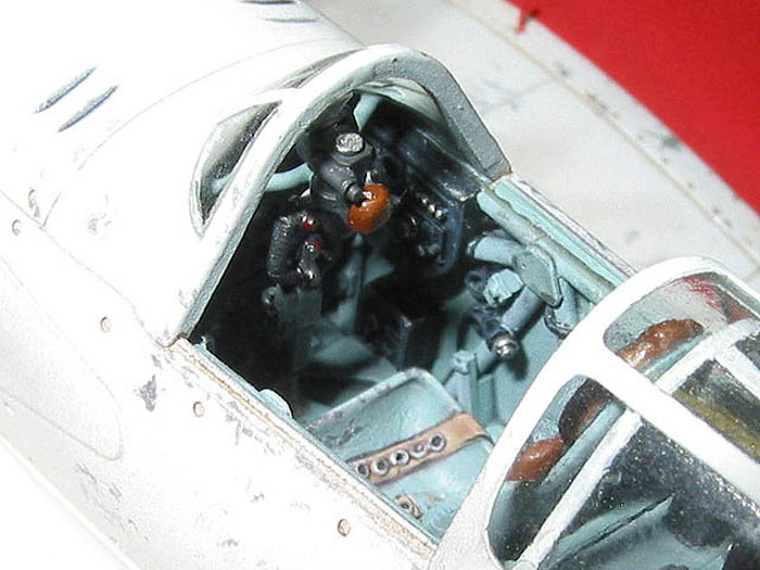
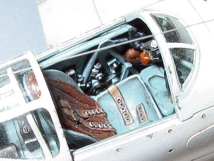
The Cockpit
The kit cockpit is quite nice, featuring a separate tubular
structure and good detail. As nice as the kit cockpit is, the Cutting Edge resin
replacement cockpit is truly marvellous. The Cutting Edge cockpit consists of 13
pieces in their typical tough medium grey resin plus a printed acetate sheet for
the instrument dials. The armoured seat has moulded on cushions and Sutton style
harness.
Vintage aircraft interior colours seem to be a perpetual point of debate between
modellers, and VVS aircraft interiors are probably the worst. Some research over
at the VVS modelling website (http://vvs.hobbyvista.com/) indicated that some
MiG-3 interiors were likely painted the same colour as the aircraft underside.
Good enough for me.
After the resin parts were carefully removed from their pour stubs, they were
painted overall Testors enamel Russian Underside Blue, with the seat cushions
painted Testors Leather and various other details picked out with black, silver
and leather. The whole cockpit was given a “wash” that consists of a mixture of
Polly Scale flat, India ink and water. It was then drybrushed with light grey
artists’ oils and some paint chipping and general scuffing added with a “steel”
coloured Prismacolor pencil.
Click the thumbnails below to view
larger images:
The Cutting Edge instrument panel is particularly nice. The builder is given the
option of painting the dials and their raised detail, or the back of the panel
can be sanded away to expose the instrument holes so that the acetate gauges can
be used. I chose the latter option.
Some careful trimming, filing and dry fitting was necessary to get the resin
components to fit properly inside the fuselage, with particular attention being
paid to the radio shelf behind the pilot’s seat. The completed cockpit was set
aside and not glued into the fuselage until later.
The Fuselage
Oh boy. Okay, so how many parts do most kits need to represent
the fuselage of a single engine fighter? Two? Three? Four? Well on this kit it’s
nine, and that’s not including the rudder!
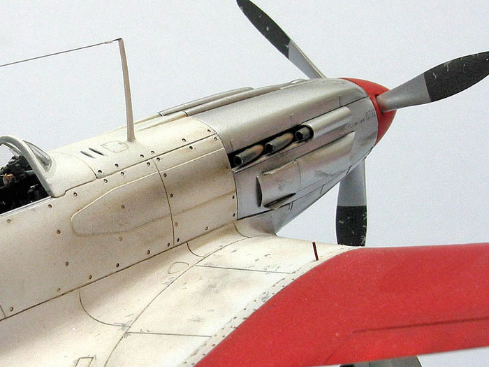
Apart from the two main fuselage halves, there are two upper and one lower
engine cowling pieces, split along panel lines. I found that these pieces had
somewhat soft edges, which would look inconsistent with the rest of the panel
lines which are quite crisp. How to fix this? I couldn’t sand the edges sharp,
as that would remove material and degrade the fit of the parts, which was
actually quite good. Instead I brushed a bead of Gunze Mr. Surfacer 500 along
the outside edges of all the cowling pieces, let it dry, brushed some more and
repeated until a sufficiently thick ridge if Mr. Surfacer had built up. I then
carefully sanded the excess Mr. Surfacer with 800 grit wet & dry sandpaper,
leaving nice sharp edges. The next order of business was to eliminate the pebbly
surface texture of the cowling, as I wanted to paint it in natural metal. An
airbrushed coat of Mr. Surfacer 1000 and a rub down with 1500 grit sandpaper
took care of that, although it was tricky work sanding in and around all of the
intakes, troughs, scoops and other surface features.
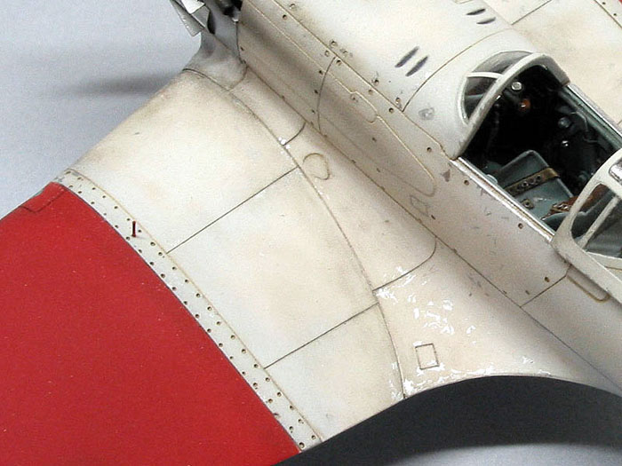
There are numerous fasteners moulded into the fuselage in the vicinity of the
cockpit that were not as well defined as I would have liked. Since they were
already fairly deep, drilling them out further wasn’t an option, so I elected to
re-do them entirely. So, I filled each one (about 70 of ‘em) with Mr. Surfacer,
sanded them smooth and then drilled each one clean trough with a No. 76 drill
bit.
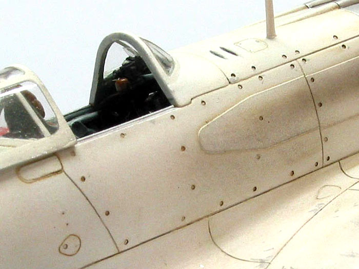
Now came the tedious part. I stretched about a gazillion pieces of sprue over a
candle, and cut pieces such that one end was thicker than the No. 76 hole, and
the other end thinner. I inserted the thin end of a piece of stretched sprue
into each hole from the outside and gently pulled it through without forcing it
until it was too thick to fit. I then cut the sprue flush with the fuselage
using a sharp new X-acto blade. Finally I pulled it through a tiny bit more
until it was slightly recessed, brushed some liquid cement from the inside and
trimmed away the excess.
At this point the cockpit parts were attached to the fuselage with five minute
epoxy to allow sufficient time to line everything up. The engine panels were
attached by brushing liquid cement from the inside so as to avoid melting the
nice sharp panel lines I spent so much effort on. Next up were the wing root
pieces which required considerable and repeated trimming and test fitting before
they were attached with liquid cement, again applied from the inside. In the
end, no filler was used on the fuselage which speaks well for ICM’s engineering,
given the complex nature of the assembly.
Disaster Strikes
It happens to all of us. Please tell me it does. Carefully cut
windscreen off of sprue. Clean up windscreen part. Admire handiwork. Fumble part
and drop on floor. Push chair back to look for part. Cringe at crunching sound
as part is crushed under chair castor.
So, I broke the windscreen in two. I emailed ICM and they charge money for a
replacement part (it was my own stupid mistake after all), so I decided to fix
it myself. First I glued the part back together with liquid cement and then
sanded polished the seam so that the surface was glass smooth. The crack was
still highly visible, so the clear portion had to be replaced. I made a mould
out of RTV rubber and cast a copy in resin which was sanded and polished to
remove the frames. This was used as a master to vacuform a new windscreen from
sheet butyrate. The clear portion of the kit part was carefully cut away and the
vacuformed replacement trimmed to fit and attached with Future. It actually
looks better than the original, but next time I’ll be more careful…
The rear portion of the canopy was attached with liquid cement after the
requisite trimming and dry fitting.
Wings and Control Surfaces
The wings, like the fuselage, are more complicated than average,
the lower portion consisting of a centre section and separate outer panels. The
upper wings are fairly conventional one piece affairs. Once more, test fitting
is the order of the day as the tops of the landing gear wells interfered with
the wing root, and the radiator recess interfered with the cockpit floor. After
removing sufficient material from these areas, a good fit was achieved and
ultimately only a little bit of filler was required between the inner and outer
lower wing pieces. In order to avoid sanding, a small amount of epoxy putty was
worked into the seam and the excess wiped away with a damp cotton swab.
The wing tip lights were carved away and replaced with chunks of clear Plexiglas
which were filed to shape, sanded, polished and painted with Tamiya clear red
and green. The fit of the landing light cover was poor, so a replacement piece
was dug out of the spared box (from the Monogram Marauder, I think), carved to
shape, installed with superglue, filed, sanded and polished to blend it in with
the rest of the wing.
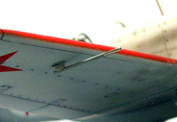
The ailerons, elevators and rudder all suffer from a grossly overdone fabric
effect which I sanded off until it was next to invisible. I used a razor saw to
cut notches in the leading edge of the rudder to portray the hinges, and added a
small formation light from clear stretched sprue inserted into a hole drilled
just below the trim tab. The horizontal stabilisers fit very well, requiring no
filler.
Because the landing gear was to be the same colour as the rest of the
undersides, they were attached before painting. The attachment of the main gear
legs was very weak looking, with only a shallow recess in the top wing. Before
attaching the legs, I drilled a hole through the top wing at the gear attachment
points from underneath. The gear were then glued on with liquid cement,
carefully aligning them front to back and side to side. After they had dried I
drilled down through the hole in the top wing into the gear legs and inserted a
length of steel sewing pin to strengthen the gear. The hole was then filled in
with superglue and sanded smooth.
Landing gear indicator pins were added to each wing from steel wire inserted
into holes drilled in the appropriate locations.
Fiddly Bits
I had obtained the Part photoetch set for the MiG-3, but only
ended up using about a third of it on the model. The photoetch set includes
parts for the cockpit (which redundant w.r.t. the Cutting Edge set) a set of
frighteningly impressive flaps (which I was too chicken to use), plus other
exterior bits. The parts I did use included the wheel hubs, radiator and outlet
door and landing gear doors. The wheel hubs were dished slightly by placing them
on a thick pad of paper towel and pressing a pencil eraser into the center.
The prop suffered from prominent sink marks near the base of the blades. These
were filled with successive layers of superglue set up with accelerator. The
prop blades were filed and sanded to reduce their thickness to something closer
to scale. The spinner was missing a panel line, so this was scribed by holding
the spinner on a flat surface and turning it against the tip of a No. 24 X-acto
blade held at the appropriate height between the pages of a book.
|
Painting, Weathering
and Decals |
I masked off the canopy with Tamiya tape which was trimmed in
place, using the well defined frames to guide a new No. 11 blade. No caffeine
for a few hours prior to attempting this exercise. The nose and stabilizers were
also masked off and the model pre-shaded by airbrushing dark grey along the
panel lines. The white (Tamiya) was airbrushed next, well thinned and applied in
thin coats to allpw the pre-shading to just barely peek through.
Blu-Tak was used to mask the demarcation line and the undersides were painted
Testors enamel “Russian Underside Blue”. This is actually a post war colour, and
even though Polly Scale produces a Great Patriotic War shade of underside blue,
it is much too garish for my tastes. I simply couldn’t bring myself to use this
more “accurate” colour for fear that my red, white, blue and silver model would
end up looking more like an Easter egg than a deadly instrument of war.
Anyway, instead of thinning the paint with mineral spirits or lacquer thinner, I
used “automotive paint reducer”. This is actually a lacquer thinner, but is
considerably less volatile (i.e. “hot”) than the regular stuff. It allows the
paint to flow nicely, adheres well and dries hard with a slight sheen.
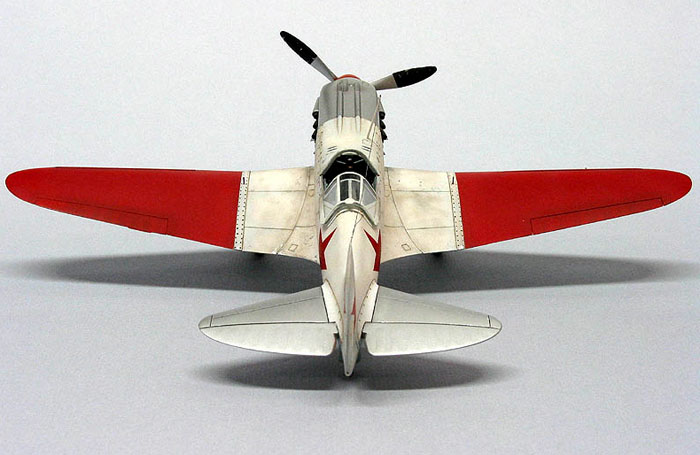
The spinner and outer wing panels were painted Tamiya flat red and over sprayed
in a random pattern with a heavily thinned faded red colour. To avoid the wings
taking on a pinkish hue, the faded red colour was mixed from Tamiya red, white
and yellow. The Soviet stars were painted on using masks cut from frisket
masking film.
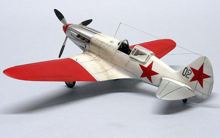
I unmasked the nose and stabilizers, and masked off the rest of the model to
paint the silver. The NMF on the nose is Alclad II “White Aluminum” which was
misted onto the unprimed plastic (gasp!). The key here was to apply the first
few coats very lightly so that they dry almost instantly and never have the
chance to craze the plastic. Risky, but it saves time if you do it right. While
the airbrush was loaded with the Alclad, the prop blades were also sprayed. The
back 2/3rds of the blades were painted acrylic dark grey and chipped with a
toothpick before the paint set up.
Weathering consisted of a Windsor and Newton burnt umber oil wash in the panel
lines and paint chipping done with Humbrol silver No. 11 and a 0000 brush.
Because the outer wings and the rear fuselage were wood, I made sure I applied
chipping only to those areas that were actually metal on the real aircraft.
General grubbiness was added with ground up chalk pastels (this was before I
discovered MiG Pigments), applied dry and manipulated with a damp cotton swab.
The engine exhausts were painted black and weathered with several shades of
ground brown chalk pastels, and the exhaust stains airbrushed on with a
brown/black colour mixed from Tamiya paints and thinned 90% with rubbing
alcohol.
The tail numbers and the little serial on the nose are the only decals on the
model, and these came from Aeromaster sheet number 48-313, "MiG-3's Early
Warriors Pt. I". Local applications of Future prevented silvering, and Polly
Scale clear flat was airbrushed after the decals and Future had dried.
I sanded flat spots on the tires and painted them Aeromaster
acrylic tire black, while the hubs were painted underside blue and glued on. The
tail wheel was painted in a similar manner and glued in place.
The pitot probe provided in the kit was set aside in favour of one made from a
short piece of stainless steel tubing. The tube was cut to length with a Dremel
tool, which was also used to round off the tip to make it look more aerodynamic.
The antenna mast was attached with superglue and the aerial was made from nylon
invisible mending thread painted Humbrol Metal Cote steel. The insulators were
made from sections of stretched Evergreen styrene tube. To make the insulators,
I heated the tube over a candle and stretched it thin, after which I cut the
insulators to length with a new X-acto blade. These were then carefully threaded
onto the antenna which was then superglued into anchor holes drilled into the
tail with a No. 80 bit. After tightening the antenna up with hot air from a
paint stripping gun, the insulators were fixed in place with a small amount of
Future brushed on.
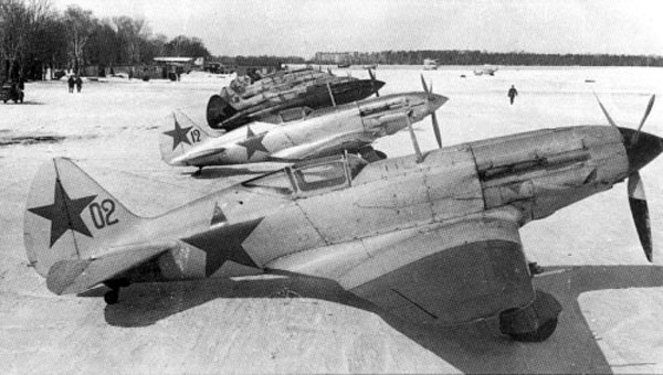
Ain’t it always the way? More information turns up after the
completion of a model, and there are several minor (or major) things wrong. So,
based on the photograph of the specific aircraft modelled, the following
potential inaccuracies are noted:
-
The spinner wasn’t red, but
rather a darker colour, probably green or even black.
-
The outer wing panels may in
fact be green as opposed to red although to my eye, the tonal value of the
wing is very similar to the Soviet stars.
-
The tail number wasn’t black,
but rather was red, again based on the comparison to the Soviet stars.
-
The nose and stabilizers may
have been some colour other than silver, based on the absence of specular
reflections (as opposed to Black 12 in the background).
-
No radio is visible behind the
pilot’s seat, in spite of the presence of the antennas.
-
There were no leading edge
slats.
For a very thorough analysis of this particular aircraft, I
refer the reader to the web page
http://mig3.sovietwarplanes.com/mig3/howred.html on Massimo Tessitori’s
excellent dedicated MiG-3 web site.
At the end of the day I’m not too concerned. Had I known I’d have done it a bit
differently, but hindsight is always 20/20.
This was a fun kit to build. It was difficult enough to
challenge some basic skills that were in real danger of becoming rusty, but it
was good enough to do so without becoming frustrating. It is a cool subject that
really stands out on the shelf next to all the P-47’s and Bf-109’s.
Click the thumbnails below to view
larger images:
Soviet Aces of World War 2
Modelling Manuals 17 |
|
|
|
|
Author: Hugh Morgan
Illustrator: John Weal
US Price: $17.95
UK Price: Ł12.99
Publisher:
Osprey Publishing
Publish Date:
October 15, 1997
Details: 96 pages; ISBN: 1855326329 |
|
|
Model, Images and
Article Copyright © 2004 by Tony Bell
Page Created 23 December 2001
Last updated 10 December 2004
Back to HyperScale Main Page
Back to Features Page |
 Home
| What's New |
Features |
Gallery |
Reviews |
Reference |
Forum |
Search
Home
| What's New |
Features |
Gallery |
Reviews |
Reference |
Forum |
Search