|
1/32 scale scratchbuilt
Federal Aircraft Factory (FAF)
N-20 Aiguillon
by Frank Mitchell
|
 |
|
Federal Aircraft
Factory
(FAF) N-20 Aiguillon |

HyperScale is proudly
sponsored by Squadron.com
Did you ever build one of those models that fought
you every inch of the way? Well, this is one of them. Lots of re-making
of things that I screwed up, or glue going into the wrong place, or
having to paint the bloody thing twice, etc. Trust me, you are never too
old or too experienced to have these things occur, nor is it any less
frustrating. However, the fact that this model was actually built at all
is a tribute to the great people that inhabit the modeling sites of the
internet.
For example, one day, while avoiding doing something constructive, I
threw out a question asking if anyone had information on obscure Swiss
aircraft. I almost immediately heard from Mike Kirk, a Brit who has
lived in Switzerland for many years. He first disabused me of the idea
that the airplane is obscure—it isn’t, in Switzerland. From then on, he
was a fountain of photographs and help, and I could not have done it
without his help. The good news, in fact, about this project is that
Mike kept sending lots of good pictures and information. The bad news
was that he kept sending me lots of good pictures, which meant that some
things had to be redone or modified as the later information became
available. There were a few cases (which I will not point out) where the
information was too late to be added without tearing the model apart,
but for the most part they were included. I had no idea so much
information about the N-20 was out there.
Background
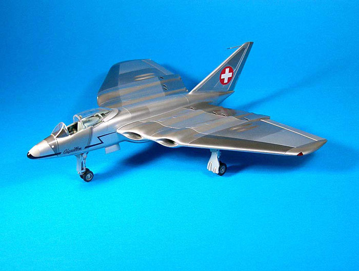
For those of you who are, like I was, rather
ignorant of this airplane, the N-20 Aiguillon (Sting) was ordered in May
1948, and contained several very new features. Its four British-derived
Mamba turbofan engines were buried in the wing, and the cold air from
the fans were ducted through additional combustion chambers on each side
of the engine. This reheat device, which doubled the normal thrust of
the engines, was to be used mainly for take-off and combat. For short
take-off and landing, the secondary airflow could be deflected through
large slots on the upper and lower wing surfaces. When the lower slots
only were open, the deflected air acted as an aerodynamic flap; with
both systems in operation, the deflected air acted as a thrust reverser.
As a substantial proportion of the air flowed through about half the
wingspan, the aerodynamic drag of the relatively thick wing was very
low. To extend endurance, two of the four engines could be shut down in
flight.
Performance estimates included a maximum speed of 680 m.p.h. at 3,280
ft.; time from 3,280 ft. to 32,800 ft., 2 minutes; take-off run 760 ft.
and landing run 777 ft.
The N-20 was designed to have a detachable weapons-bay that could be
changed in 10 minutes. Alternative loads were 1,764 lb. of bombs, six
20-mm. cannon, four 30-mm. cannon, thirty-two missiles, cameras or
additional fuel. Two 20-mm. Cannon were permanently mounted in the nose.
Anticipating the F-111, the pilot was provided with a watertight escape
capsule, ejected by an 8,810-lb.thrust rocket.
Due to problems with its engines, development of the N-20 was cancelled
in 1952. It was not flown, although it did have a number of high-speed
taxi tests and, according to one source, actually did lift off for a
short distance.
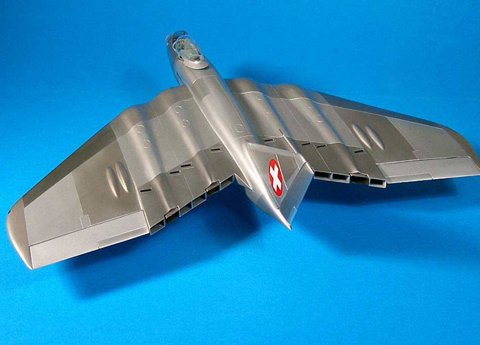
The model is an excellent example of the old adage
that the simpler something looks, the more complex it can be. Although
the lines are lovely, the intakes, along with those curvy engine
fairings, the exhaust/bypass outlets, the cockpit, and the landing gear
all combine to make a difficult-to-capture-and-look-decent shape. As
usual, the pictures will show most of the construction, and probably
better than words.
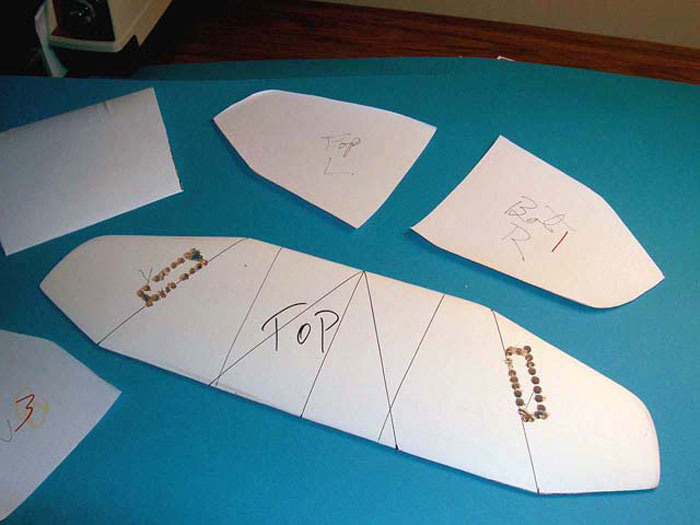
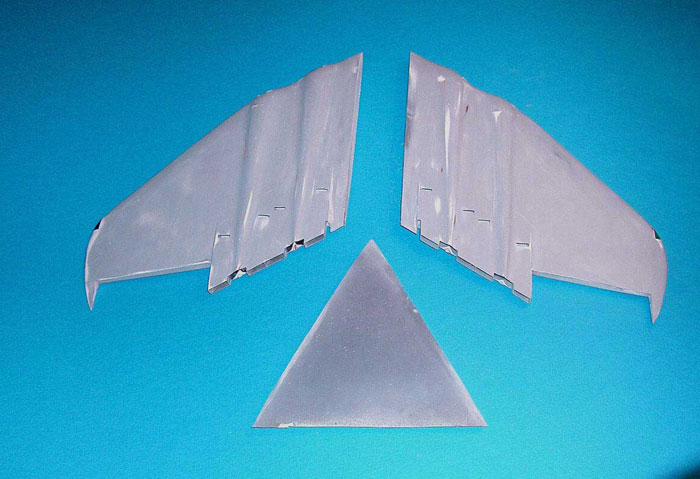
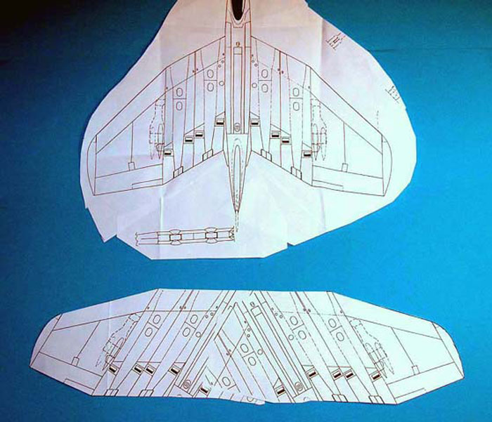
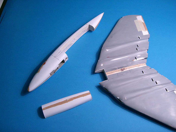
It seemed impractical and a lot of excess work to build the wing as it
is on the airplane, so the drawings were manipulated to make a straight
piece. It did mean constant checking to assure that everything would be
straight when the wings were finally cut apart, but it made life much
easier while getting there.
Once the basic wing was cut and sanded to shape it was formed using my
usual technique for big pieces, i.e., clamping the styrene in door
hinges and heating and smashing. The main wheel wells were cut into the
outer wings and the wells themselves made up from styrene sheet. The
skins were then attached to the wings with epoxy. Now the real fun
began.
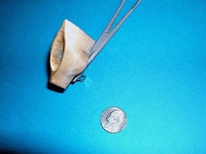
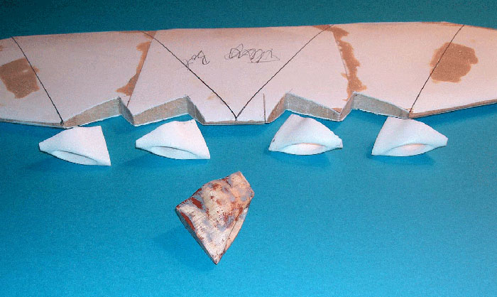
The first thing tackled were the intakes. After some thought, it seemed
that the easiest way to get identical, smooth intake surfaces inside and
out was to mold them from resin. In order to do that however, one needs
a mold. So, on a dull Saturday afternoon, I sat down with a chunk of
basswood and drilled, carved, and sanded away. 3 hours later, I had the
master seen in the pictures. A mold was made from RTV, and four intakes
were made. The appropriate openings were cut into the wing leading
edges, but before they could be mounted, I needed to find some engine
faces. They are close to the intake lips and very visible. After some
prowling through the backlog, I found some perfect ones in the exhausts
of a 48th S-3 Viking. I used one of those to make an RTV mold and did
four of them (This model was much like a ship in its need for
replication; that bloody wing needed either 4, 8, or 16 of everything).
Notches were cut into the wings so that the engine faces would be
equally spaced behind the intakes, but before they were glued into
place, the exhaust and fan outlet areas were built.
Click on the thumbnails
below to view larger images:
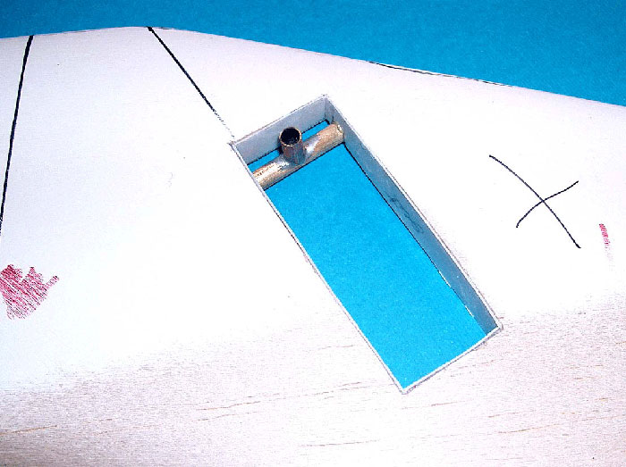
An section was cut from the wings the size of the
exhaust areas. The rest is probably easier seen in the pictures than
described in words, but basically the whole structure was built-up from
sheet styrene. Just couldn’t figure out any other way to make sure
everything was open and visible they way it should be. Once complete,
the two sections were epoxied into the wings, as were the engines and
engine faces.
A simple mold was cut from balsa for the main engine fairings and eight
of them were heat-and-smashed, cut out, and glued into place on the top
and bottom of the wing. Now the entire wing was filled and sanded ad
nauseum until everything looked straight and smooth. The control
surfaces were cut from the wing, nav lights were put into place, and the
wing was ready for the dramatic moment of being cut apart and
reassembled at its proper sweep back angle. It was, and everything even
lined up properly. Amazing. Riding on that high, I (thankfully) put the
wing aside so that the fuselage could be attacked.
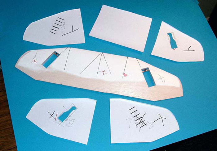
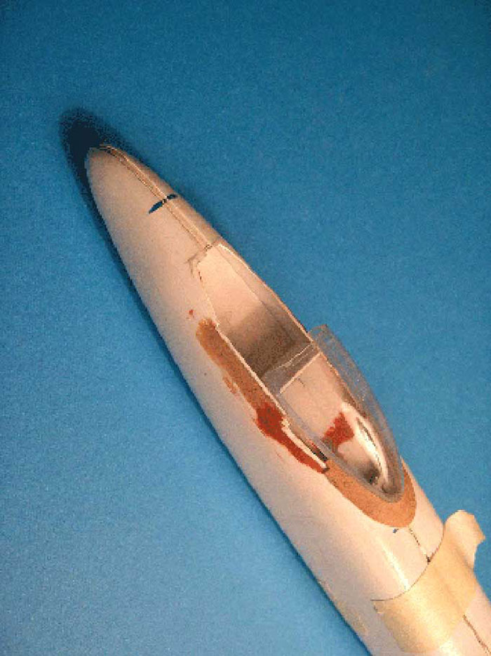
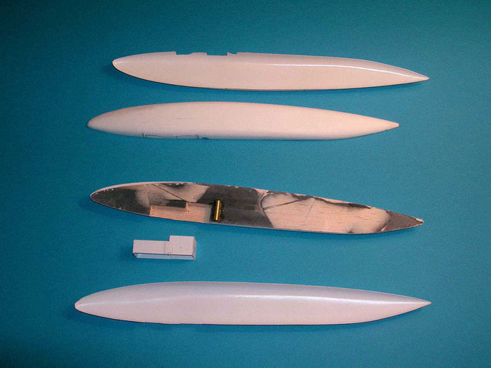
The fuselage was vacuum-formed over my usual balsa molds. The nose wheel
well was the first opening cut, and the well itself made up from sheet
styrene which was painted and detailed.
Click on the thumbnails
below to view larger images:
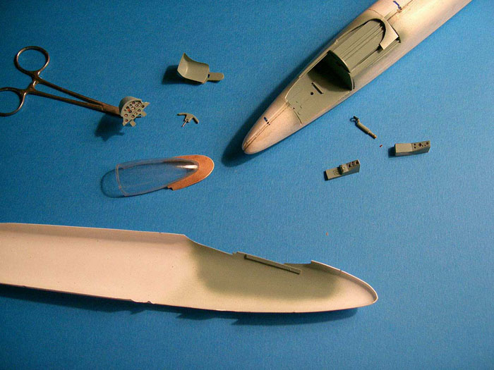
The cockpit opening was cut out and lined with
styrene sheet. The consoles were made from balsa and also covered with
thin sheet. The instrument panel was made in my usual way; a sandwich of
styrene backed with clear vinyl and having the instruments white-glued
to match the holes in the outer styrene. The control column was made up
from various bits and pieces of aluminum tubing and brass wire, and all
the usual cockpit detailing was added.
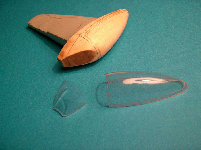
As an example of the earlier statement about this being a complex
project, the canopy, of all things, turned out to be a bit of a hassle.
For reasons that I assume had something to do with the escape capsule,
the N-20’s canopy is attached to a fairing that slides with it as it
opens. The fairing is rather thin and, to make life more interesting,
the canopy to which it attaches is entirely framed in clear plexiglass.
I could have just closed the thing and gone on with my life, but
cheaters never win, so after a bit of head scratching, my approach was
to carve a basswood mold for the windscreen/canopy and heat and smash
several vinyl copies. Then, on the mold itself, a line was drawn which
outlined the inside of the inner framework. One of the canopies was cut
down to that line, while another was cut to the overall canopy outline.
These were then (carefully) glued together with superglue, and the edges
sanded and polished. Next, the fairing was cut from sheet styrene and
glued to a spacer that was shaped to the bottom of the canopy. This
assembly was glued to the canopy itself, and epoxy was used to form the
final shape. Involved, but I couldn’t think of any other way to do it.
The windscreen also had its problems, again caused by the ejection pod.
There is a clear plexiglass panel at the rear of the screen, covering
the area of the arch. From a modeling standpoint, that means that the
windscreen is a sealed chamber, and that the fit has to be decent or it
won’t look right (or good). This was tackled by taping the windscreen to
the fuselage and carefully measuring the distance between the bottom
edges. That was then duplicated off the model using tape to make the
windscreen have the same shape it would have on the finished model. The
arch was then traced onto cardboard and then onto clear vinyl, measuring
and shaping all the way. When the fit seemed to be reasonable, it was
glued using very small amounts of superglue while trying very hard not
to get my fingers as well. The completed windscreen was not actually
glued on until the last second before painting began.
Once that was finished, the fuselage was put on the building board and
the outline of the wing cross-section was drawn on its sides. That area
was removed, and the wing was fitted in place. It was not glued yet;
lots to be done before that took place.
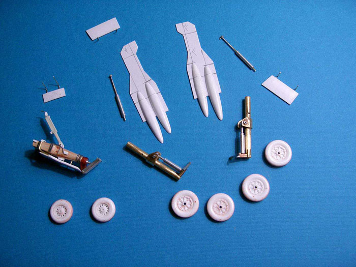
Next up was the landing gear, since they are all three trailing link
designs, and were made from brass and aluminum tubing with a bit of
soldering and supergluing. There was also some basswood used for the
nose gear leg shape; it surrounded a piece of tubing that supplied the
strength. Other bits and pieces included some square aluminum tubing,
and some colored plexiglass (the bottom of the nosegear that was also
the pivot for the trailing arm). The wheels were cast in resin using for
masters a main wheel from an ancient Monogram TBM (main wheels) and
something from the discarded parts stash (nose gear). The gear doors
were built up from sheet plastic.
A mold was made for the small wheel fairings that are on the top and
bottom of the wing, and eight copies heated and smashed. These were cut
out and glued in place, although the bottom ones were applied in several
pieces as they were attached to the geardoors as well as the wing. The
relevant gear doors also had to be modified to reflect the fairing
shape.
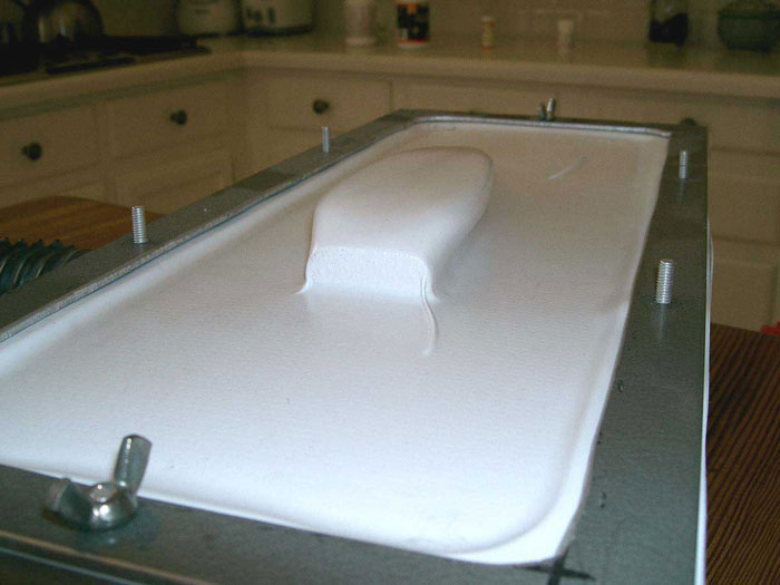
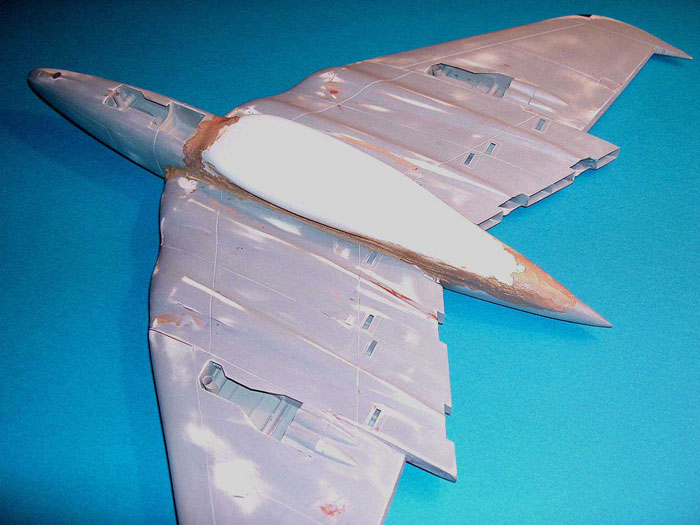
Next came the weapons pod. Don’t let anyone tell you that you can’t mold
undercuts using a vacuum-forming setup. You can; it just takes a little
thought. The mold was carved and sanded from balsa and smoothed using my
favorite primer, Kilz. The mold was then vacuum-formed in the same way
as the other pieces of the model, just using care and patience to make
sure that the plastic is as warm as it will get, short of melting. Then
turn on the shop-vacuum, and quickly place the warm plastic over the
mold. I also use a pair of soft gloves to make sure the plastic has
followed the shape. The result can be seen in the photos. Note that this
really doesn’t work very well with sharp-edged shapes, but in this case,
the curves of the pod did very well; a bit thin, but useable.
Click on the thumbnails
below to view larger images:
With all the main components built, it was time for
a little priming and sanding followed by scribing of panel lines,
hatches, etc. When that was finished (if it ever is), the wings were
glued into place, followed by the weapons pod, followed by the fin, with
lots of sanding, priming, and scribing taking place between each step.
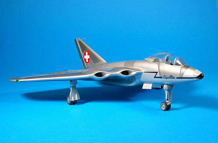
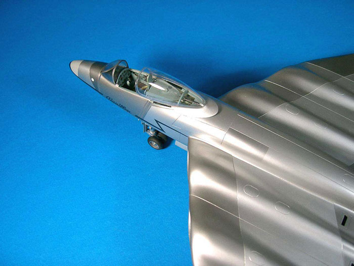
Natural Metal Finish
 The
airplane was in natural metal when it was tested, and that I what I
decided to do. I did cheat in one respect; I left off the nose test
probe. Looks much cooler that way. The
airplane was in natural metal when it was tested, and that I what I
decided to do. I did cheat in one respect; I left off the nose test
probe. Looks much cooler that way.
I used Alclad, masking off various panels using frisket. The control
surfaces, and other small parts were painted with varying shades of
Alclad and Testor’s Flat Aluminum. As I said earlier, I completely
screwed up paint job #1 and, after letting the thing sit for a couple of
weeks, I sanded off all the old paint and started over.
Markings
The decals are few; the Swiss tail marking came
from a Hunter decal sheet, and the sweep spear was a combination of
paint (forward), and decal sheet (aft). The name was done by the simple
expedient of blowing it up to 8.5 x 11, and tracing it with the blackest
marker I could find.
When reduced to a little over an inch long, all the
jiggly lines disappeared and it was copied on to clear decal sheet. I
looked hard at all the pictures I had, but could not find any of the
tiny-written so common today. Either it was too small, or I missed it.
So anyway, it is (finally) finished, and it does make an intriguing
addition to the collection. For anyone coming to the Atlanta Nationals,
it will be on display; just don’t look too close.
Click on the thumbnails
below to view larger images:
Model, Images and Text Copyright ©
2005 by Frank Mitchell
Page Created 01 June, 2005
Last Updated
01 June, 2005
Back to
HyperScale Main Page |
 Home
| What's New |
Features |
Gallery |
Reviews |
Reference |
Forum |
Search
Home
| What's New |
Features |
Gallery |
Reviews |
Reference |
Forum |
Search