Home
| What's New |
Features |
Gallery |
Reviews |
Reference |
Forum |
Search
Home
| What's New |
Features |
Gallery |
Reviews |
Reference |
Forum |
Search
|
|
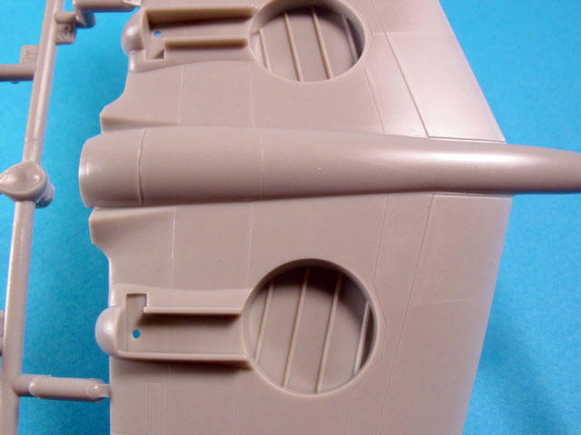
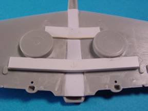
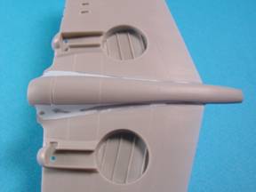
After cleaning up the cut with a knife and a bit of sandpaper, assemble the wing to the spars created earlier with superglue using the scribed outlines to line everything up. Next fill the hole left by the fairing with some thick sheet plastic and fill and sand any gaps with superglue. With this done, it is simply a matter of replacing the fairing at the correct height and refining the shape with 3-M Acryl Blue putty. (Fig. 3)
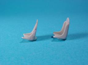
Return to NormalityWith the above bit of surgery out of the way you can heave a sigh of relief and look forward to building the rest of the kit that presents few other hassles. Depending on how careful you are in installing the spars, you may need to do a bit more trimming at the wing roots to get everything together but we’ll deal with that later. I probably enjoy working on the cockpit section of kits most of all and that’s where I turned my attention next. The HobbyCraft cockpit is not too bad and is the best out of the box option of the three 1/48th scale kits. I wanted to use the kit cockpit but couldn’t resist making a few enhancements. The seat is the weakest part of the cockpit and could easily be replaced. I elected to modify the kit part, as I wanted to preserve my Meteor Productions cockpit sets for the Trumpeter and Monogram kits in my collection where they are really needed. Surprisingly, the accurate shape of a P-40 seat may be found lurking beneath the surface of the kit part. I used sandpaper to thin the sides of the seat and scribed in the recessed ribs in the seat back. I used thin strips of plastic to represent the ribs on the rear and sides of the seats and added some small discs punched from plastic to create some rivet detail. I carved some lightening holes in a thin strip of plastic and added it to the seat pan to finish off the part. After a bit of effort, the appearance of the seat is much improved compared to the original. (Fig.4-5)
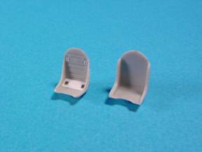
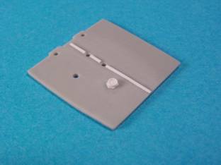
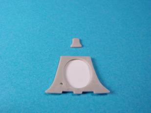
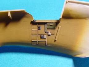
Beyond the seat, the rest of the cockpit is quite nice. I just added a bit of ribbing and a fuel gage to the kit floor. (Fig. 6) I also added a blanking plate to the rear bulkhead. HobbyCraft molds this part open as do the aftermarket sets by Meteor but my references indicate that there was a cover installed here. I also re-shaped the headrest to better match my reference photos (Fig. 7)
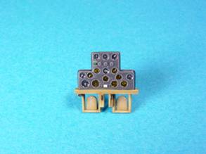
With all of the detailing out of the way, painting the cockpit was fairly straight- forward. I mixed a suitable interior green shade from Tamiya acrylic paints. When dry, I dry-brushed the interior with Testors enamel zinc chromate lightened with yellow and white. I like using enamels for dry brushing because acrylics tend to clump and dry too fast for the technique. The various boxes and fittings were painted with black and individually dry brushed with light gray enamel. (Fig. 8) I painted the instrument panel in a similar fashion and picked out individual dials with Prismacolor artists’ pencils. I finished off the dials with drops of clear gloss and clear yellow. (Fig. 9)
With the cockpit painting finished, I installed everything and assembled the fuselage and wing halves according to the instructions. Fit was generally good, though I applied a bead of super glue to all of the seams and sanded it away when dry. This is a good insurance policy against visible seams later down the road.
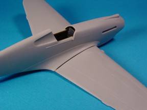
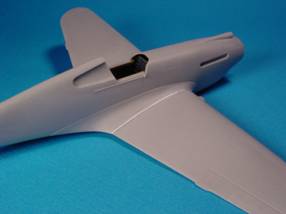
Inevitably (with me anyway) major modifications to a kit give rise to some unexpected problems. As I mentioned earlier, the wing modifications caused a change in the opening between the upper wing halves making it narrower than the fuselage. In these cases, you just have to be flexible and adapt. I used a number ten X-acto blade to carve a bit of the wing root away on either side of the fuselage. This allowed the wing to be fitted to the fuselage but left a substantial gap along either side of the fuselage. (Fig. 10) I installed shims fabricated from sheet plastic to fill most of the gap and covered the remainder with superglue. When sanded out, the seams were filled and perfectly blended. (Fig. 11) Superglue is a wonder filler as long as it is sanded right away. Don’t leave it longer than 20 minutes or it will harden too much to be sanded!
With the wings mated and all seams filled, the model was ready to be primed and painted.
| ||||||||||||||||||||||||||||||||||||||||||||
|
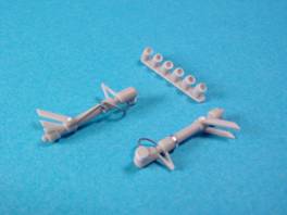
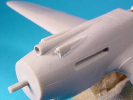
Fig. 12: A bit of solder and plastic discs really improve the appearance of the gear struts. Opening the exhaust stubs makes big difference. |
Fig. 13: The cowl .50 caliber Machine guns were opened with a pin vise. The fairings were blended in with 3-M Acryl blue putty removed with a damp Q-tip dipped in nail polish remover while still wet. |
Construction |
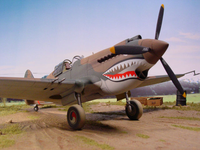
For this model, I wanted to try a technique I found described on the Tamiya Website by Andrew Dextras called “dual diffusion.” This basically turns the traditional method of painting the model from the lightest shade to the darkest on its head. To begin, the model was first primed in a very dark grey color achieved by mixing flat black and flat white Tamiya paint. At this stage I checked for any flaws that required additional filling. To my amazement, there were none.
For the next step I applied the dark green color for the camouflage on the topside of the aircraft. Again this was derived from a mixture of primary colors from the Tamiya range to match photos found in the excellent Eagle Editions publication, “Tigers Over China”. Next the lighter olive/tan shade was added. Finally, I flipped the model over and applied the light gray underside color. In all cases, I attempted to apply the colors in a cloudy random manner allowing the darker color underneath to peek out. This was intended to add depth to the finish and replicate the manner in which the elements weather the paint. I went over each color with a lightened tone that was applied in random streaks from front to back on the wings and top to bottom on the fuselage sides to further the effect. I was fairly pleased with the results, however, I’ve concluded that I should have left the finish a lot more uneven and patchy and let the darker primer show through a bit more as the later weathering really subdued the effect.
Weathering
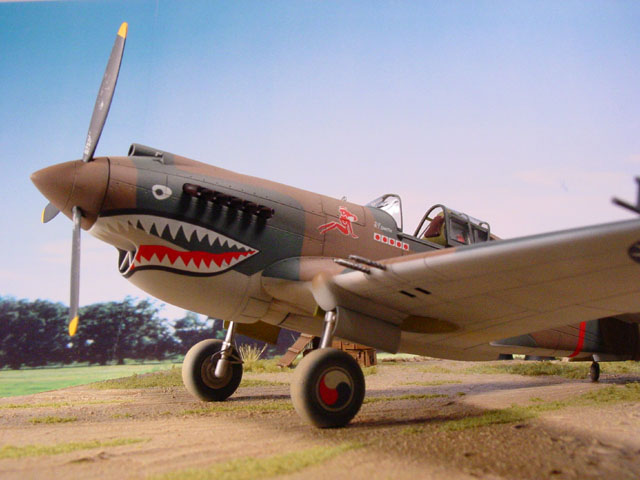
I turned to the weathering after applying a glosscoat, decals and flat coat. Mr. Dextras’ article proposes highlighting the panel lines by spraying over them with a thinned mixture of black and brown. I was not confident of my ability to get that much control with my airbrush so I resorted to a conventional wash of thinned oil paint. In this instance I used raw umber for the topside and Payne’s Grey for the bottom. I added oil leaks and streaks with a thicker mixture of oil paint and used a mixture of black and brown pastel chalks to replicate the powder stains around the guns and shell ejection ports. I applied chipping with a silver Prismacolor pencil. After a final flat coat to seal everything together, I finished off the weathering with a very light overspray of a light buff (tan) color over the entire model to blend all of the weathering and tone down the decals. I used the kit decals and aside from a tendency to break if flexed too much, they proved to be excellent and the best I’ve seen in a Hobby Craft kit.
I replicated the position lights by first painting them with a dark grey color. I then added a dot in the center of each light with a very light grey/ off white. Finally the entire light was over painted with the appropriate clear color from the Tamiya range. This technique gives the impression of a clear light and is much easier than trying remove the molded lights and replace them with clear stock.
After adding all of the detail parts and a stretched sprue antenna, the model was complete.
Base and Figures |
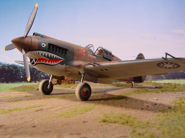
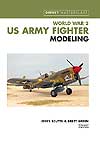
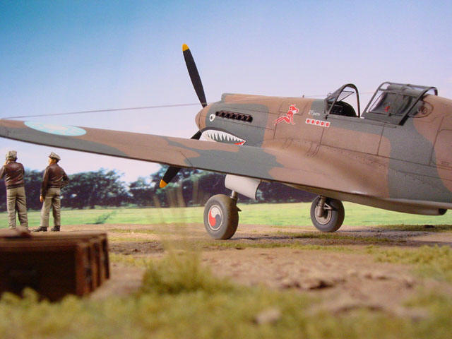
I used two excellent figures from the Wingz line from VLS. They were very well cast and a joy to paint. The base was made from 1” foam insulation with ground cover represented by tile grout. Some crates and barrels were added to create more visual interest to the scene.
The model, figures and base were photographed against an enlarged photo taken in Savannah, GA, my boyhood home, that reminded me of the wartime photos I’d seen of China and Burma. It looked closer than suburban Maryland in any event.
Base and Figures |
Click the thumbnails below to view larger images:
|
|
|||
|
|||||||||||
Back to HyperScale Main Page