|
Classic Airframes' 1/48 Scale
Hawker Sea Hawk FB.5
by
Stephen Naylor
|
 |
|
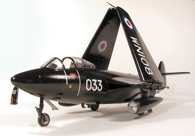
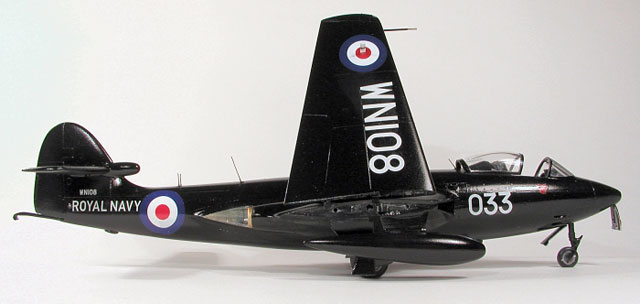
Hawker Sea Hawk FB.5
WN108 ('033') |

Classic
Airframes' 1/48 scale Hawker Sea Hawk is available online from
Squadron
For a look at the contents of
Classic Airframes' 1/48 scale Hawker Sea Hawk,
see the in-box
review elsewhere on HyperScale.
Armstrong Whitworth Sea Hawk FB.5, WN108 ('033'),
was operated by Airwork Services Limited FRU (Fleet Requirements Unit)
from their base at Hurn Airport (now Bournemouth Airport) in Dorset
(UK), from June 1958 to August 1963. Airworks used various marks of Sea
Hawk at Hurn, as well as other types, in order to provide gunnery target
practise and radar calibration for warships of the Royal Navy, during
exercises off the south coast of England.
Sea Hawk FB.5's were basically the FB.3 model
fitted with the uprated Nene 103 engine, a conversion carried out by the
original manufacturer on this FB.3 airframe (#AW6041) in 1955. In this
way, all FB.5's were conversions - there were no production examples.
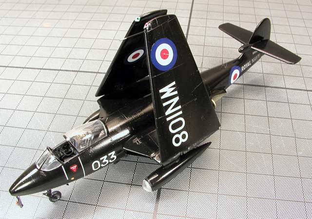
As soon as I heard that CA was to produce a Sea
Hawk, I knew that the aircraft I would model would be one in the FRU
Hurn 'all-over black' finish (more on this later), but which one?
Whilst there are several Hurn-based examples I would like to have done,
I eventually chose 'WN108', mainly because 'Kits at War' (Dutch Decal)
produced a timely decal sheet featuring the aircraft (their sheet #K4/13
'Royal Navy Postwar'). This avoided the need for me to source
appropriate decals from elsewhere, especially being a black aircraft
requiring white lettering and numbers of the correct size and style. As
a bonus, this aircraft is also preserved at the Ulster Aviation Society
Heritage Centre in Northern Ireland, though the only useful photograph I
have found to date of 'WN108', is the one on page 15 of Warpaint No.29.
Sea Hawk 'WN108' Details
In terms of the subject-specific features or
modifications I undertook on the kit, these were just two comprising;
●
No fins on the under-wing drop tanks (a feature of FRU/Hurn
Sea Hawks)
●
Port drop tank to be fitted with a searchlight (Harley
Light?) in its nose. [This searchlight 'pod' was an aid to target
acquisition by ship-board gunners during exercises, as was the all-over
black finish. Choosing to fit this pod is a bit of 'modeler's license'
on my part, as although this feature is shown on other aircraft of the
time, I have no actual proof of one being fitted to 'WN108'].
Summary
Although they will be mentioned shortly during
the build steps, here is a quick list of the other corrections or
modifications I made to the kit;
●
Opened the canopy (to show off all that excellent
resin/etch).
●
Opened the cannon ports under the nose.
●
Opted for folded wings.
●
Added scissor links to main undercarriage leg oleos.
●
Discarded use of photoetch (PE) Parts 'PE8', 'PE9', 'PE10'
and 'PE14/15'
(the engine intake guides
– see later).
●
Replaced the kit's stubby resin jet pipes with longer
(internally) brass tubing.
●
Added the curiously missing 'tail bumper' to the tail.
Other than the decal sheet mentioned earlier and
my own scratchbuilding efforts, no aftermarket accessories were used,
though I was tempted to replace the ejection seat with something more
detailed. However, given the long gestation of this build and the
'issues' I had (some kit-related, some of my own making), I went with
the kit seat to save time (and my sanity!).
Finally; CA's Sea Hawk FB.3/FGA.6/FGA.50 kit has
already been extensively reviewed elsewhere, so as usual I do not
propose to repeat what has already been said. On the other hand there
are some 'issues' with the kit which will have an influence on the
modeler's 'experience', so I will mention them where appropriate.
Extras
●
Kits At War's (Dutch Decals) 1:48 decal sheet K4/13 'Royal
Navy Postwar' (www.kitsatwar.nl).
Getting Underway
In describing this build, I will follow the kit's
instruction sheet sequence and parts numbering, though this is not
necessarily the order in which I proceeded. Although I realise this is
not as convenient for those without access to these instructions, I
think it will still work with a bit of explanation along the way, and
perhaps be of more use to other modelers faced with the open box of
parts.
STEP 1
(Instrument Panels)
One of the delights of the kit for me, was the
depiction of the main and front quarter instrument panels. After
dipping the clear acetate instruments sheet in Johnson's 'Klear' floor
polish, and allowing to dry, I sprayed the rear face of it with white
automotive primer (as per the instructions), so that the dials, etc,
would show up better. The faces of the panel etches (Parts 'PE1', 'PE2'
and 'PE3') were then sprayed with black automotive primer, followed by
dry-brushing with white enamel paint to pick out the highlights and
added a few lamps picked out with a fine brush in appropriate colours.
These latter parts were then secured in place over the appropriate areas
of the aforementioned instruments acetate with superglue. Once trimmed
out of the acetate, three beautiful panels resulted, the best I have yet
seen on a model. Strange therefore, that some subsequent CA kit
offerings (Meteor NF and Canberras for example), only have simple
moulded-plastic instrument panels. However, moving on...
STEP 2
(Cockpit Wall Instruments)
No problems here. Resin pieces 'R13' – 'R16' fit
fine and similarly benefit from dry-brush work and detailing (check your
references).
STEP 3 (The Cockpit)
One of the 'problem areas' with this kit is
squeezing that resin cockpit tub (Part 'R1') into the fuselage.
As indicated in most reviews, a considerable
amount of material had to be removed from not only the sides, but
particularly the base, of the main cockpit tub resin casting. In fact,
the floor of mine ended up so thin, that it actually separated from the
base! Despite all this fitting and sanding however, I was still not
really able to get the two fuselage halves (split horizontally) to meet
properly. This ultimately led to some filling and sanding of the mating
seams, with consequent loss of panel line detail, requiring re-scribing
later. That said, the the side panel detail of the cockpit tub is good
and shows up well once painted (lightened black) and picked out in
appropriate colours (references again).
The gyro gunsight (Part 'R3')
and its 'film' reflector glass (I only fitted one of the two required -
my eyesight is not what it was!) was painted and left to be fitted after
final painting, as was the joystick and ejection seat (Part 'R2'). On
the subject of the seat; it passes muster but the perfectionists amongst
you will probably want to replace it with a more-detailed aftermarket
specimen. For simplicity's sake I chose to use the kit seat, though
fitting the PE parts was fiddly. In the end, the retractable knee guard
etch (Part 'PE13') broke off once too often for my patience, so I
discarded it.
STEP 4
(Lower Fuselage Internals)
No problems here. The resin main wheel wells
('R7') and intake duct housings ('R5' and 'R6') are superbly moulded and
fit with little other attention. Do not forget the required weight in
the nose (10g + suggested: see later for further problems I had in this
regard), otherwise you will end up with a 'tail-sitter'.
STEP 5
(Closing the Main Fuselage Halves)
For me, this was an area where I undertook some
technical modifications, partly to correct a problem, and partly to
enable a more secure assembly. Obviously this was my decision and I'm
sure others will do things differently, but anyway here goes...
The kit instructions require that the jet exhaust
pipe mounts (Parts 'A8' and 'A27'), which form part of the aircraft's
two jet pipe 'pen-nib fairings', are fixed in place between the fuselage
halves (after some fitting and fettling) and then the tail assembly is
butted on to the rear of the closed fuselage halves in the next step. I
was not happy about this method for a couple of reasons.
Firstly, as the parts ('A8' and 'A27') form part
of the 'pen-nib fairing', the majority of which is actually ed onto the
tail halves (parts 'C1' and 'C2'), it is therefore important that they
line up correctly with the latter, rather than just fitting them to the
main fuselage and then having to accept the resultant alignment the kit
sequence gives you. Secondly, I was also not that happy (from a visual
perspective) with how short the actual resin jet pipe 'cans' were (Parts
'R9' x 2).
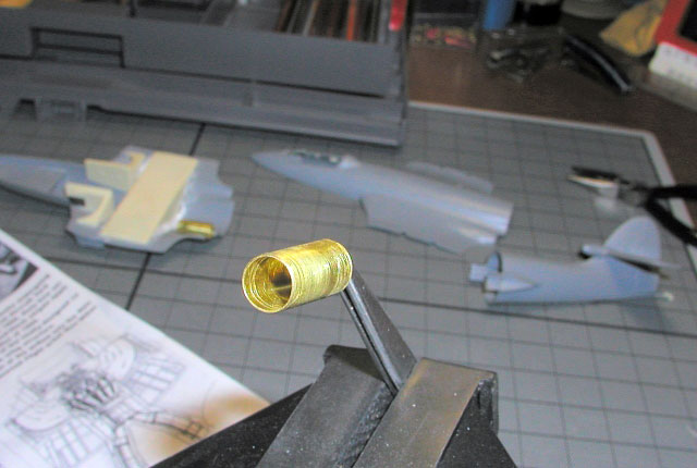
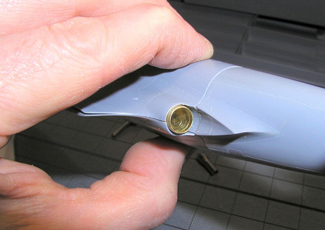
To solve that, I substituted two of my own jet
pipes made from suitable thin-walled brass tube and placed a couple of
mounts for them (ex-1/72 Airfix Lancaster wheel centers I think, from
the scrap box), inside the lower fuselage half in order to fit the pipes
to them, after final assembly. These scrap 'mounts' also have the
advantage of stopping the pipes from disappearing completely inside the
body when you do come to fit them! Fitting the pipes later also allowed
me to paint them, and the natural metal finish (NMF) 'pen-nib fairings',
as separate items later, rather than as an assembly. Note, that if you
do use the CA-supplied resin jet pipes, there is a problem in that the
location 'pips' moulded on parts 'A8' and 'A27', which determine where
the supplied jet pipe 'cans' ('R9') are positioned, are actually cast
too far aft anyway (in reality, the ends of the jet pipes barely emerge
from the rear of the outer part of the fuselage fairing).
So if you are still with me, the upshot of all
this is that I actually fitted parts 'A8' and 'A27' (having first
removed those location 'pips') to the assembled tail in Step 6, and
offered that sub-assembly up to the dry-assembled fuselage halves, so
that I could get the tail/'pen-nib fairing' spot-on before closing the
fuselage permanently. More on that in Step 6.
The fit problems at the cockpit end have already
been mentioned, so what else? Well the only other problem (for me) is
with the intake duct splitter plates (Parts 'PE8', 'PE9' and 'PE10') and
their respective 'top plates' (Parts 'PE14' and 'PE15'). The problem,
is that the kit shows them as being fitted flush with the leading edge
of the intakes, 'ala' DH Vampire. In fact, these actually curved
(rather than straight) guide vanes are in reality much further back (and
staggered aft) inside the intake ducts and can therefore hardly be
seen. This is especially true in the case of my model, as the insides
of the ducts were going to be black anyway. As a result, I left all
this PE out completely, though I did still fit the boundary layer
splitter plates (Parts 'PE11' and 'PE12') next to the fuselage here,
back in Step 4.
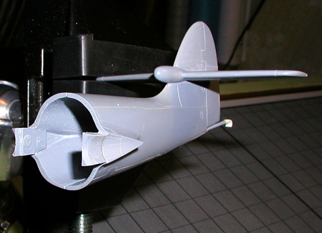
STEP 6
(Tail Assembly)
See Step 5 above for how and why I did things
slightly differently here. One or two things are worth mentioning
though. The main thing, is that despite my best efforts, and in keeping
with the experience of many other modelers at this point, I failed to
get a good match between the cross-sectional profile of the tail
sub-assembly (split vertically) and that of the main fuselage (split
horizontally), at this important butt joint. Not sure if it was all my
fault or partly the shape of the kit's moulding, but in the end I again
had to resort to a fair bit of filling/sanding/re-scribing around this
joint after assembly, to restore its smooth aerodynamic shape. Remember
also to fit something appropriately shaped to the underside of the tail,
to represent the rubber 'bumper' seen in this location (for some reason,
CA left this feature off this kit's tail, but did provide it on the
'Mk.101' version).
Other pointers are: don't do as I did and fit the
tailplane (Parts 'A3/A4') to the tail sub-assembly early on, to 'make
some progress'. Wait until AFTER the tail is actually assembled to the
fuselage, so you can sight back over the top of the fuselage and get the
tailplane parallel with the wing (or wing stubs if opting for folded
wings). I couldn't wait however, and although the tailplane seemed
square when I fitted it to the tail assembly there is, even now, still a
slight tilt towards Starboard after I assembled the tail unit to the
fuselage. Whilst this 'tilt' may be mostly of my own making, it might
also be because once assembled the tail itself seems, for some reason,
not to be quite vertical with respect to the fuselage?
Just one final don't here. Don't fit the
arrestor hook now; wait until just before final painting - the resin
hook-end on mine broke off three times(!). Luckily 'The Carpet Monster'
failed to get it!
STEP 7
(Wing Assembly - Deployed)
Not followed - see Step 8.
STEP 8 (Wing Assembly - Folded)
The wings were no problem really. Getting the PE
on the hinge end of the wing halves to stick with superglue was fun
(Parts 'PE16' and 'PE17'), and they needed some trimming to match the
wing profile. Though the resin parts (Parts 'R17' and 'R18') fitted
reasonably well to their respective points in the fuselage, one of the
paradoxes of this method of providing the wing-fold, is that the PE on
the ends of the folded wings is very good (but will not really be seen),
whilst the resin parts on the fuselage (which are more prominent) do not
really represent this area too well at all.
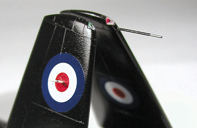
As is my preference, I also fabricated clear
plastic wingtip lights port and starboard, drilled-out and filled with
red or green food colourant as appropriate.
In lieu of suitable microtubing, I substituted a cut-off dressmaking pin
for the kit's pitot tube on the port wingtip.
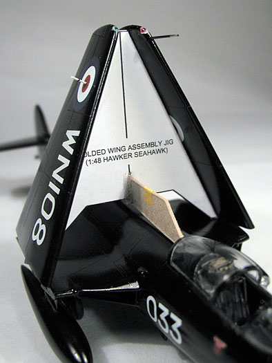
The wing sub-assemblies were painted and decaled
separately, then assembled to the fuselage using a card jig I designed
with CAD on the computer, to provide symmetry and support whilst the
glue set.
Click on the thumbnails
below to view larger images:
STEP 9
(Nose Wheel Assembly)
No real problems here. With care, you can leave
the wheel ('R10') off until later and squeeze it between the forks of
the nosewheel oleo ('A16' and 'A25') after assembly and painting. The
only other improvement, was to beef-up the PE arrestor wire guard
('PE5') with some superglue gel, once fitted, and then sand it to a
shape more like the forging it represents.
STEP
10 (Main Wheel Assembly)
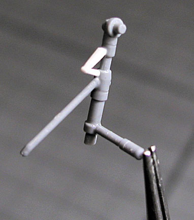
Again, this is all pretty much straightforward.
To help assembly of the main undercarriage (Parts 'A13'/'A29',
'A18'/A24' and 'A20'/'A22'), I drilled a fine hole into the fuselage end
of each gear actuator ('A18'/A24') and also into the corresponding
location points for that actuator in the resin main wheel wells ('R7').
This was done, so that a short piece of fine wire could be glued into
the end of each actuator, both to assist with location during final
assembly and to help with undercarriage strength. Although a small
detail, I also added the missing scissor link to each mainwheel leg,
sourced from the scrap box (removed from ex-1/72 Airfix RA-5C Vigilante
undercarriage units I think) though in truth, they can hardly be seen on
the finished model.
One other thing to watch in Step 10, is that the
kit's instruction sheet shows the resin catapult strop hook ('R12'), as
being fitted in a position aft of the rear gunbay access doors. In
reality, this hook is mounted just forward of the chainlink/shell
ejector chute access panels (you will see a small rectangular engraved
panel area for it, at the correct location). On the prototype, this
hook was retractable, though my reference photograph and many others,
show that in practice it was usually left in the deployed position.
Finally here; the shell ejector chute parts ('A19' and 'A23') need their
upper ends attended to, in order to get a good fit against (and the
slight outward angle from) the fuselage.
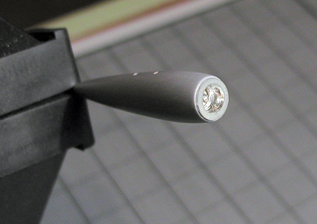
STEP 11 (Underwing Stores and Doors, Etc)
As mentioned earlier, I fitted the two drop tanks
('B5'/'B6' + 'B7'/'B8') to the two inner stores pylons ('A21' x 2),
having first modified the tanks to FRU specifications.
Initially, this involves removing the rear fins
on each tank (a standard FRU Sea Hawk feature). Additionally, on this
aircraft, the Port drop tank was then further modified by having its
nose cut back and replaced with a glazed searchlight (Harley Light?).
The light unit was made from a scrap rear rocket motor (chromed plastic)
from an old 'Zero-X' toy from my childhood - remember that? (the toy,
not my childhood!). To finish it, a large-headed dressmaking pin
represented the bulb.
The searchlight's glazed nose/lens was made by
'heat-smashing' some clear plastic sheet over the end of the resin radar
nose left over from CA's NF.21 Sea Hornet kit. Once cut out from the
sheet, this glazing was then attached to the tank with white wood glue.
I had no drawings for these tank modifications, I just roughly scaled it
from the reference photos I had to hand.
Everything else at this stage went together OK,
though I obviously didn't need the second set of stores pylons ('A21'),
one under each folded wing, for this aircraft.
Click on the thumbnails
below to view larger images:
STEP
12 (Canopy and Other Details)
This final step on the instruction sheet, mainly
covers the fitting of the cockpit canopy ('C1').
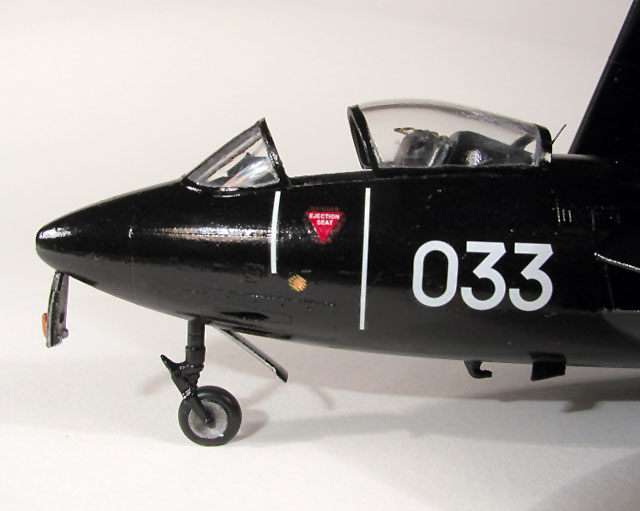
What should have been the most difficult part of
this (separating the canopy into two halves to allow the sliding section
to be displayed open) was, in the end, the easiest. Merely a simply
operation with a razor saw, followed by sanding and polishing to cleanup
the cut faces. Once the front (fixed) canopy section had been painted
internally, it was secured to the nose with superglue (using the sliding
canopy section as a guide) and any resulting gaps between it and the
fuselage filled and rubbed down. The sliding section of the canopy was
masked and painted separately, then secured to the fuselage with white
wood glue on final assembly.
Step 12 also covers the fitting of one of the
many antennas (i.e. 'PE7') - though other antennas are expected to be
fitted in preceding steps. In my case, I elected not to use any of the
PE antennas from the kit's fret. This is firstly because I don't think
that PE is necessarily a good representation of these things (my
thoughts are, 'just because you can etch something, does not mean you
should'. Secondly, most of these antenna are better left off until
after final painting and finishing anyway. Normally, I use fine wire or
bristles from a brush for the wire-type antennas and shaped Evergreen
strip for the blade-type UHF antennas (e.g. the one in the centre of the
roundel, under the starboard wingtip). There is a good reference
diagram covering all possible antenna 'fits' to Sea Hawks, on page 30 of
the '4+' book (see the reference list at the end).
The usual filling and sanding was undertaken and
once cleaned up, the cockpit area and glazing was masked off, as were
the wing-tip navigation lights and the tip of the pitot tube (that metal
pin), on the separate wing assemblies. Parts such as the main
undercarriage and nosewheel oleo assemblies, the wheels, undercarriage
doors, sliding canopy and the pair of jet pipes were left off to be
painted and weathered separately and assembled later.
So, on to the painting. Should be simple - its
just black isn't it? Well the exterior of the airframe is, but what
about the wheel wells, undercarriage and wing-folds? The kit
instructions are silent with regards the wing-fold area but as usual,
suggest that the wheel wells and the inside of the undercarriage doors
should/could either be aluminium or the same colour as the underside of
the aircraft.
From research and photos, I know that Hurn's
Fleet Requirements Unit (FRU) received their Sea Hawks from the Fleet
Air Arm in their last service scheme and then repainted themselves in
black. However, that then raises the question; what scheme was 'WN108'
in when received by the FRU in 1958? Barring any exceptional
circumstances, the underside options are clearly either 'Sky' (more
likely?) or White (less likely?). Even if I knew that (and I do not),
the next point is whether the FRU would have left the wheel wells and
insides of the undercarraige doors as delivered (for simplicity's sake)
or would they have gone to the trouble of repainting them? From a
maintenance point of view, I cannot imagine that black for these areas
is a good idea, but I could be wrong of course. To add to the
complexity, my only photo of 'WN108' shows that this aircraft had (as
with some other, but not all, FRU black-finished machines) a black
nosewheel strut/oleo. Of course, this photo and many others of Sea
Hawks does not show the main undercarraige clearly, making it difficult
for the modeler to confirm whether they too were painted black. This
problem is compounded by the fact that on an aircraft with such a short
undercarriage, this area is often in dark shadow. In the end, I decided
that I would go with black undercarriage legs and aluminium/silver for
the wheel wells and hubs, as well as the inside of undercarriage
doors. For the wing-fold, I decided on black, partly because the few
(b/w) reference photos of black Sea Hawks with folded wings I have, seem
not to show a light colour (aluminum or 'Sky'?) in this area, and partly
because black tends to hide the relatively poor representation of the
wing-fold joint on the fuselage.
Having thus, finally, decided the colour scheme,
the interior of the wheel wells, the inside of the undercarriage doors,
the wheel centres, the ejector seat, the interior and exterior of the
masked canopy and the wheel hubs all received a spray coat of cellulose
automotive Silver primer from a 'rattle can'. With the exception of the
ejector seat and the canopy, all then received a very dilute wash of
black enamel paint to accentuate the detail. The wheel wells were then
masked off using damp tissue and the model, plus the wings, the exterior
of the undercarriage doors, the undercarriage assemblies, the ejector
seat and the exterior of the sliding canopy, were then sprayed with a
coat of cellulose automotive Grey primer, also from a 'rattle can',
followed by a top coat of Humbrol Matt Black. Once dry, these areas
received a couple of light coats of Johnson's 'Klear', prior to
decaling.
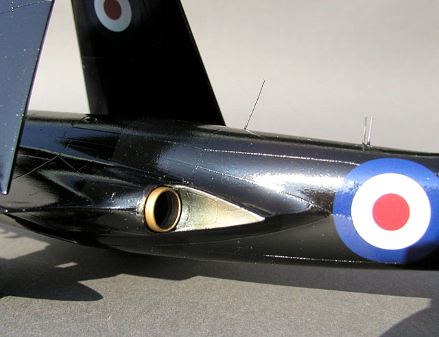
Using the 'Klear'-coated black finish as a base,
I separately masked off the engine exhaust 'pen-nib fairings' and,
together with the painted exhausts themselves, sprayed them with Alclad
II 'Polished Aluminum'. Afterwards, I tried Tamiya acrylic 'Clear Blue'
('X-23') and 'Clear Orange' ('X-26') on these areas to simulate heat
discolouration of the stainless steel, but without a great deal of
success - need more practice. Perhaps on my next project I'll give
Bare Metal Foil a try and see what happens.
The appropriate decals from the 'Kits At War'
#K4/13 sheet were then applied, using 'MicrolSol' and 'MicroSet',
seemingly with no problem, followed by a second coating of 'Klear' to
seal them. Some slight silvering has since become apparent, but it is
only visible under close scrutiny and strong lighting (e.g. in digital
photos!). Thinned Humbrol Gloss Varnish provided the airbrushed
finishing coat.
Prior to assembling the undercarraiges to the
airframe, the tyres were picked out in Matt Black and weathered slightly
(dry brushing), remembering also to add the pairs of white 'creep marks'
to each tyre/wheel rim (including the nosewheel). To complete the
model, the various wire and strip antennas were then fitted and the
wings assembled in their final position using the card jig I mentioned
earlier.
Unfortunately, as alluded to earlier on, when the
finished aircraft was placed flat on a level surface, I had still ended
up with a 'tail-sitter' (insert profanities here)! Locations for adding
extra weight were, by now of course, severely limited. In the end, I
had to feed some fishing weight 'shot' into the roof of the nosewheel
bay and pour in some epoxy glue to secure it in place. Although an
unsightly solution, should you happen to pick up the model and examine
it, the Sea Hawk does at least now sit flat on its wheels unaided, but
only just - Phew!
Perhaps one of the most difficult 'post-build'
tasks has been to take some decent photographs. Trying to photograph a
shiny black object has proved to be quite a challenge, whether indoors,
or outdoors, natural or artificial light or flash, automatic or manual
settings! Even now, I am not that happy with the results, but at least
digital photography allows for endless experimentation. Of course, you
do have to bear in mind that gloss black does have a tendency to show up
the slightest flaw on any model and its paint job, especially to the
unforgiving lens of a digital camera (that's my excuse and I am sticking
to it!).
Would I build another Classic Airframes Sea
Hawk? Lets just say its not high on my list of priorities, and I don't
have one in the unbuilt kit 'stash'. Having said that, I am pleased
with the final result and it is the best kit of the 'Hawk' around,
though for me, it was a 'trying' build and there were times when I
thought I would never get it finished. Still, there are also markings
for an all-red FB.3 Sea Hawk of the 1958 'Red Devils' aerobatic team on
that 'Kits At War' decal sheet, so as a former Bond once said, 'never
say never again'...
-
Hawker Sea Hawk; Tony Buttler MRAeS; Warpaint No.29; Hall
Park Books.
-
Hawker Sea Hawk; Michal Ovcacik, Karel Susa, et al; Mark 1
Limited, 2001; 4+ Publication.
-
Hawker Sea Hawk - Type History Database; Derek James;
Aeroplane Monthly; September 2002; p.47 -69
-
Hawker Sea Hawk; Richard J Caruana; Scale Aviation Modeller;
1996?; p.156 -163
-
The Fleet's Hawk; Richard J Caruana?; Modelaid Quarterly,
Issue 3; 1980's?; p.83 - 88
-
The Hawker Sea Hawk; Francis K Mason; Profile Publications;
1966; No.71
-
http://daveg4otu.tripod.com/fru.html This is a webpage
(part of a larger 'Aviation in Hampshire, UK' website) dedicated to
the Airwork Fleet Requirements Unit, listing all the aircraft that
worked at Hurn before the Unit was relocated to Yeovilton in 1972
The photographs were taken with my Olympus
Camedia 4040 Zoom camera on a tripod, mostly using aperture priority
setting (to preserve some depth of field), close/'macro' focusing and
occasionally 'AEL' (exposure lock). The latter was tried in order to
read exposure from a grey card, rather than relying on the automatic
reading from the camera's sensor when pointed at the shiny black model.
The final choice of images were then adjusted, sharpened, cropped and
re-sized using Paint Shop Pro7. Most are indoor shots, lit by up to
three angle-poise lamps fitted with daylight bulbs.
Click on the thumbnails
below to view larger images:
Model, Images and Text Copyright © 2006
by Stephen Naylor
Page Created 12 December, 2006
Last Updated
21 February, 2007
Back to
HyperScale Main Page |
 Home
| What's New |
Features |
Gallery |
Reviews |
Reference |
Forum |
Search
Home
| What's New |
Features |
Gallery |
Reviews |
Reference |
Forum |
Search