|
Dynavector's
1/48 scale vacform
De Havilland
Sea Vixen FAW.2
by Ingo Degenhardt
|
 |
|
DeHavilland Sea Vixen FAW.2 |
images
by Lutz Degenhardt

HyperScale is proudly supported by Squadron
There are quite a number of bizarre-looking British aircraft from the
1950’s and one of them is certainly the Sea Vixen by DeHavilland.
Developed from the D.H. 110 prototype it was DeHavilland’s proposal for
an all-weather fighter bomber demanded by RAF and RN.
When the RAF finally went for the Gloster Javelin, development work
continued now focusing on the carrier-based version only.
Despite a catastrophic crash of one of the prototypes (WG 236) at the
Farnborough Air Show in 1952 work on the Sea Vixen continued and finally
it was accepted by the RN to replace the Sea Venom (also by D.H.). In
1959 the first squadrons were equipped with the Sea Vixen FAW.1
It soon became apparent that the FAW.1 suffered from insufficient range
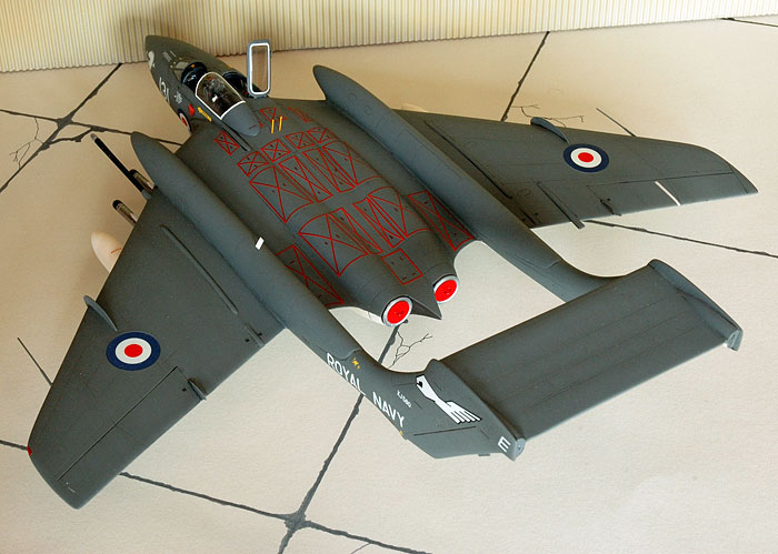
– a problem solved with the introduction of the FAW.2 with it’s enlarged
twin booms, now extending over the wing leading edges, carrying
significantly more fuel. With this and some further improvements the
FAW.2 became the final version of the Sea Vixen from 1962 on. Total
production included 119 FAW.1, ob which 67 were converted to FAW.2
standard and 29 new produced FAW.2 aircraft.
Sea Vixens remained in service with the Royal Navy until 1972, when 899
squadron aboard HMS Eagle was disbanded as the last squadron equipped
with Sea Vixens.
Many of the now surplus Sea Vixens still saw service at various test-
and evaluation units for several years and 11 were converted into
remotely controlled D3 drones.
I just had to have a Sea Vixen – in 1/48. So there was no other
choice than Dynavector’s vacuform model. I was a little bit concerned as
this would be my first vacu and the twin-boomed Sea Vixen being not
quite an ideal object for vacuform-beginners.
I finally decided to give it a try and read a lot about vacuform
modelling and it’s peculiarities. Good preparation always is useful and
especially here, where the most important operations are due right at
the beginning.
Opening the plain box I discovered two big white rectangular plastic
sheets containing the outformed parts. A smaller variant for the clear
parts and a heavy plastic bag with white metal parts. Furthermore a
surprisingly rich decal sheet and the 6-page instructions.
Looked like a lot of work. And it was.
I started by removing the main parts (25 pcs) from their plastic
environment. Accuracy is the most important thing during this stage,
because the fate of the model is already decided here. With a permanent
ink marker I drew a broad line around each part, carefully making sure
no white spots are left on the marker’s black line. Then a sharp hobby
knife is drawn around the part, following exactly the shape of the part,
held at a 45 degree angle. Only moderate pressure is applied. After
repeating this operation several times I started to bend and twist the
part carefully to break it from the sheet. With the cuts deep enough it
should break exactly along that line. May be here there some additional
knife work is necessary as the thickness of the plastic varies
sometimes. The separated part now has a thin black line around it. This
line indicates exactly how much surplus material now has to be sanded
off – i.e. everything White below it. The black line has to be strictly
obeyed.
Now it gets a little bit difficult – neither too much nor too less
plastic must be removed. Both causes a lot of trouble later during
assembly.
I used a sanding block and a sheet of sanding paper taped to the desk
for the sanding operations, changing between the two whenever the one or
the other seemed to work better for the task I was working on.
Permanently checking the progress is an absolute must as the sanding is
easily overdone. Removing and sanding the parts is a lot of work and
takes a while to finish, but finally I had my 25 parts in front of me.
Now the marked openings for cockpits and wheel wells had to be cut out.
Some care is needed here too – the parts can easily be damaged in the
process, and again, not to cut out too much as this is very hard to
correct.
From now on everything is just like a normal injection moulded kit –
almost.
In case of the Sea Vixen the engraved panel lines had to be partly
rescribed as they are not always continuous. Some (vertical tail plane)
are wrong and/or incomplete and had to be corrected. Assembly of the
main components is mostly trouble-free as long as one pays heed to the
recommendations from the instructions. Reinforcing some of the joints
from the inside is no mistake either.
The numerous white metal parts require a good deal of preparation
because they are rather rough and there is a lot of flash. Even though
Dynavector is considered a top-manufacturer of vacu-formed kits, not all
necessary parts are contained. I had to do some scratchbuilding. But
first I had to find out what was missing – Dynavector does not tell.
Good references are essential here.
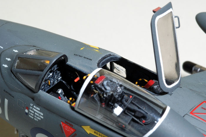
Except for the tubs the cockpit parts are completely white metal and
provide a good base for the extensive work that is inevitable if you
want a detailed cockpit. It also serves as bow weight, but to be sure I
added some lead to the front fuselage.
The seats were a disappointment – they do not even meet the detail of
modern 1/72 standards, not even close. I immediately forgot about them
as there are some excellent Martin-Baker Mk.2 ejection seats by Airwaves
available.
Depending on personal preferences and/or skill limitations any amount of
detail can be added to the cockpits, just make sure the seats will still
fit in afterwards. In case of the observer’s ‘black hole’ this only
makes sense when the canopy is displayed in the open position.
Windscreen and canopy of the pilot have to be shortened considerably
on their right lower edges because attached as they are, they will show
a prominent angle to the left which is wrong. They are straight just
like any other cockpit – only on the left half of the fuselage. This
goes as well for the pilots instrument panel.
In addition to cockpit detailing other scratchbuilt items were:
A little bit of extra detailing I added to the wheel well covers and
main gear actuators. The leading wing fences are white metal parts and
much too thick. I used thems as a pattern to make new ones from thin
plasticard.
So it’s a lot of work, this Sea Vixen, but slowly it approached the next
step – painting.
Painting
Now here everything is familiar business.
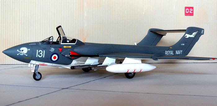
The standard Fleet Air Arm Sea Vixen had upper surfaces in Extra Dark
Sea Gray and undersides in White.
I used Xtra-Color X5 for the EDSG and Humbrol White – both gloss colors
that provide a perfect surface for the decals.
I did some weathering by lightening up the EDSG a bit for the initial
paint job and then used the original paint to spray along engravings,
shadowy areas and so on. A few random cloudy patterns were sprayed on
too.
A wash with heavily diluted flat black enamel followed, during which the
lower fuselage and wings received a rather heavy treatment of the wash
as most in-service Sea Vixens showed a very dirty underside; at least
this is my impression from several photographs.
Decals
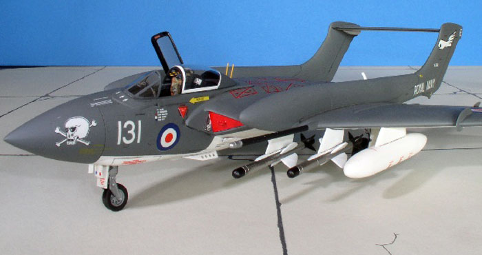
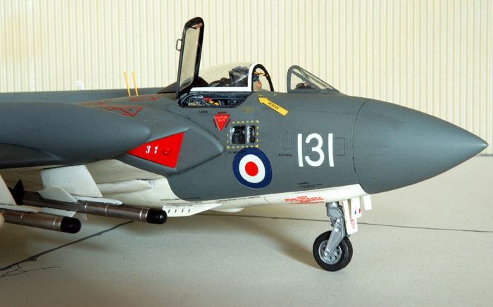
The already mentioned rich decal sheet provides markings for three
aircraft – two planes of 899 squadron/HMS Eagle; ‘131’ with a skull and
crossed bones as nose art and ‘137’ with a sharkmouth and brightly
colored flowers painted on the underside of the horizontal stabilizer.
Both aircraft date from the early seventies. The third option is one the
colorful D3 drones in cream yellow and red – 1980/81.
The decal sheet even had complete stencils but in general I was a little
bit suspicious looking at the decals – they were flat and had a very
thick carrier film. But there was no other choice at the time, so I
started work and soon was surprised at the good behaviour they showed:
There was nearly not silvering (not even among the mass of red
walkway lines on the fuselage top) and despite their thickness they
reacted quite well to Microscale Set & Sol. So no serious problems on
irregular surfaces. The only extra-treatment they needed were two coats
of clear flat to make them blend into the surface.
I used Humbrol Matt Koat for the finish although Sea Vixens were
initially painted glossy but this seemed to have faded rather fast
during active service and on many photographs the paint look quite flat.
To fit the weathering done beforehand, I went for a flat, used-looking
clear coat.
All in all I am very satisfied with the result and will have no fear
to make another vacuform model in the future. Of course there are some
things I could have done better but I think I have learned a good deal
and will avoid some mistakes next time.
May be a Gloster Javelin or a Fairey Gannet…
Model and Text Copyright © 2005 by
Ingo Degenhardt
Images Copyright © 2005 by Lutz Degenhardt
Page Created 18 August, 2005
Last Updated
17 August, 2005
Back to
HyperScale Main Page
|
 Home
| What's New |
Features |
Gallery |
Reviews |
Reference |
Forum |
Search
Home
| What's New |
Features |
Gallery |
Reviews |
Reference |
Forum |
Search