|
A-Model's 1/72 scale
Tuploev Tu-128
Fiddler
by Jim Rotramel
|
 |
|
Tuploev Tu-128 Fiddler |

HyperScale is proudly supported by Squadron
Well, Sports fans, somebody has to go first, and I just couldn’t resist
taking on A-Models Fiddler kit. Hopefully, what I learned will help your
build go a bit smoother. I would put the “ease” of building this monster
somewhere between the Testors B-2 and a Mach II kit (Yikes!).
Remember kids, this is a
limited run kit (and a very ambitious one at that!). I’m NOT
complaining, just letting you know that if you demand Tamiyagawa fit,
you’re going to be severely disappointed!
I never dreamed I would have an opportunity to build this Cold War
interceptor, and am overjoyed that this kit is as good as it is.
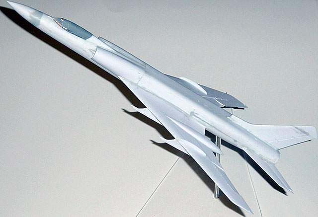
First Impressions This was
an enormous aircraft—a fighter as big as a B-58 Hustler! I suppose it’s
because of the limitations of the A-Model molding equipment, but the kit
has many more pieces than you would expect from Monogram or Hasegawa. For
instance, the nose wheel well has separate pieces for the top and each
side, each exhaust has five pieces, each main gear bogie has 17 pieces
(!), etc. There is a fair amount of flash, especially around the smaller
parts, but nothing unmanageable. I’m going to generally follow the
instruction sheet sequence in this review.
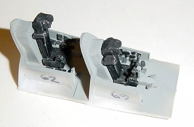
Cockpit (Steps 1, 2, & 4)
The cockpits are nicely detailed for 1/72, but unless you plan on cutting
apart the single piece canopy to open the them, virtually none of it will
be visible once the kit is built. I did note that parts 68 and 69 (the
front cockpit sidewalls) are reversed on the instruction sheet. Other
nits: 1) The ejection seats are too narrow. 2) The control yoke (part 73)
on mine had been pulled from the mold too quickly and was slightly
deformed. 3) The rudder pedals/control column base (part 72), if assembled
using its locating pin, will be off-center (just delete the locating pin)
and you’ll probably want to drill a hole in its top to insert the control
column into.
Aside from the nits, it all fit together well and the assembly fits well
into the top front fuselage (part 104). To prevent sanding dust from
creeping into the cockpit after the canopy was installed, I cut a 17mm
diameter half disk to close off the front of the interior and sealed the
whole cockpit assembly into the fuselage with a seam of superglue along
the edges.
Landing Gear (Steps 3 & 9)
As you can see from the photos, I built my Fiddler “gear up” (as I do all
1/72nd kits), but here are some observations. As previously mentioned,
there are a LOT of parts to the landing gear assemblies and the very
delicate parts have a fair amount of flash on them, so cleaning up for
assembly will require some care. Overall, I think you can build this “gear
down” without undue difficulty. The one thing you’ll want to change is the
nose gear installation. It is designed to be installed in the nose well
and then into the fuselage nose section as it is assembled. If you’re half
the ham-fist I am, this WILL be broken during subsequent assembly!
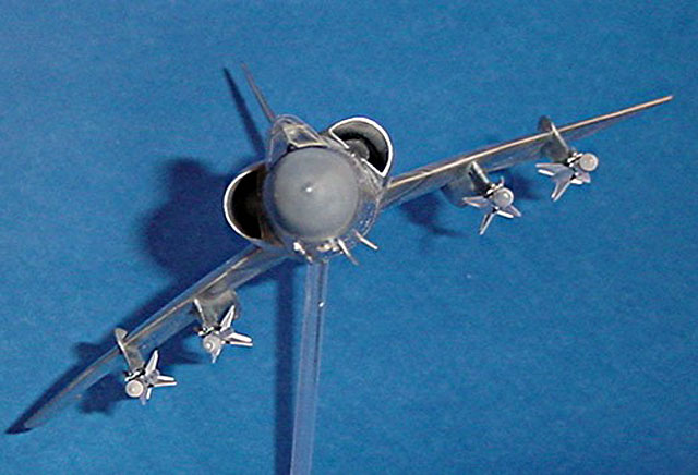
Exhaust Nozzles (Step 5)
 This
was the most curious part of the kit for me. While the rest of the kit
seems accurate, the nozzles don’t resemble ANY of the photographs I have
of the Fiddler. (BTW, Linden Hill has some very helpful photos on their
web-site.) My first hint came when I tried to assemble parts 27 and 31,
found they had the same diameter and asked, “Why did they do that?” Then I
began looking at photos and discovered that what was in the kit bore
absolutely no resemblance to the real thing. What I ended up doing (and
this is much easier than it sounds) is making my own. I bought 1/2” and
5/8” diameter brass tubing; cut two 3/4” segments of the former and two
1/16” segments of the latter using my trusty Dremel with its Emery wheel
attachment (AND eye protection!). I then superglued strips of plasticard
on the outside of the long tubes, fit the rings over those assemblies
about one width back, then cut off the short part of the strips at the
exhaust end of the nozzle and glued on the kit’s turbine faces. It only
took about an hour to do both and I think they look pretty good (at least
they look something like the real thing!). This
was the most curious part of the kit for me. While the rest of the kit
seems accurate, the nozzles don’t resemble ANY of the photographs I have
of the Fiddler. (BTW, Linden Hill has some very helpful photos on their
web-site.) My first hint came when I tried to assemble parts 27 and 31,
found they had the same diameter and asked, “Why did they do that?” Then I
began looking at photos and discovered that what was in the kit bore
absolutely no resemblance to the real thing. What I ended up doing (and
this is much easier than it sounds) is making my own. I bought 1/2” and
5/8” diameter brass tubing; cut two 3/4” segments of the former and two
1/16” segments of the latter using my trusty Dremel with its Emery wheel
attachment (AND eye protection!). I then superglued strips of plasticard
on the outside of the long tubes, fit the rings over those assemblies
about one width back, then cut off the short part of the strips at the
exhaust end of the nozzle and glued on the kit’s turbine faces. It only
took about an hour to do both and I think they look pretty good (at least
they look something like the real thing!).
Wings (Steps 6 & 7 & 12)
What is it with kit manufactures these days? They seem obsessed with
individual control surfaces. I remember them going through that phase back
in the 1960s and thought they had outgrown it. I guess everything old is
new again. I would be happy with thin trailing edges—but things are what
they are.
You need to remember to install the carry-through box (part 21) between
the right wing upper and lower halves (parts 6 & 17) and then assemble the
left wing upper and lower halves (parts 7 & 16) around it to form the
complete wing. I found that the end of the lower wing halves needed to be
thinned a bit to eliminate a “step” between the upper and lower parts. One
thing that annoyed me was that while they provided separate flaps, there
was no indication of how to pose them in a lowered position (if desired).
Also, they don’t fit very well. The instructions show the flaps (parts 8 &
12) and ailerons (parts 9 & 13) being installed from behind the
wings—you’ll actually be fitting them from the top or bottom as that is
the only way the hinges and slots align. The inboard flaps won’t fit
without some thinning of their forward bottom “tongues”. Also, on one
side, the bullet hinge fairing on my kit’s lower wing could have used some
filing on the side that is hidden after assembly to improve the fit of its
inboard flap. On the right side, I found it necessary to add a thin strip
of plasticard to the landing gear pod’s inboard flap fairing to eliminate
a gap when the flap was fitted. The other side fit fine.
I added the wheel pods here and was glad I did. These are the poorest
fitting parts of the kit. They are too narrow at the rear and require
substantial filling on both sides. If I was building it “gear down”, I
would have assembled the landing gear making sure they fit into the
locating holes on the top wing (Parts 6 & 7), then glued the lower pod
pieces to the wing and after all the filling and sanding was finished,
insert the gear later.
Fuselage I (Steps 4, 8 & 10)
Before assembling the upper and lower front fuselages, you’re instructed
to drill out holes for the landing lights (parts 109). The clear pieces
themselves are physically small, difficult to make round because of flash,
and too large in scale. I took a “that looks about right” (TLAR) approach,
drilling out holes that looked about the right size, gluing the clear
pieces on the inside, inserting small rhinestones into the holes from the
outside, filling them with superglue or clear epoxy, and later sanding
them flush.
On my kit, the top front fuselage half was slightly wider than the bottom
half. The bottom half has a tongue at the back to “help” when fitting it
to the lower back fuselage (Part 1) and wing assembly. If used, it will
prevent the lower front and back halves from mating flush. I cut mine off.
What you WILL want to do is cut a 1 x 3/4” piece of THICK plasticard and
insert it the 1-inch dimension between the top and bottom front fuselage
halves from the back to spread them so they will mate flush with the
assembled aft fuselage.
I left the radome off until the rest of the fuselage/wing assembly was
completed.
Fit the wing to the aft fuselage. I trimmed the fuselage fillets for the
inboard flaps, which were about 1/8 inch too long, but in retrospect, this
may not have been the best thing to do. What you might want to think about
before you glue the wing and lower fuselage together is trimming the
fillets so that theystart flush with the fuselage and fair smoothly into
the flap trailing edge.
I next glued the front fuselage assembly to the bottom aft fuselage (Part
1) and wing assembly. Once satisfied with the alignment, I set that
assembly aside to dry and harden overnight.
Inlet Ducts (Step 10)
The
inlet spikes (parts 29 & 30) don’t fit cleanly to the fuselage, but be
careful when filling and sanding the resulting gaps as the flat inlet ramp
is very thin and can inadvertently be sanded in the process. The inlet
ducts (parts 18 & 19) and compressor faces (parts 22) should be assembled
as a unit and allowed to dry before you start to manhandle them. Before
installing them, grind away the exposed lip around the edge of the
compressor faces. The assembly then fits (sort of) to the front fuselage,
but filling and sanding along the entire inlet assembly will be required
to make these suckers seamless! Lacking definitive information on what
color the Fiddler intake ducts were, I looked at available photos of other
Soviet aircraft from that era and ended up making a mix of Metalizer Burnt
Metal and Brass. In any event, by the time everything is assembled, very
little of the ducts will be visible. I wasted a lot of time on this. My
recommendation is to forget about in inlet ducts as they are difficult to
see even with a flashlight after the model is assembled and save the
compressor faces for some other project.
Fuselage II (Step 10)
To
get the top rear fuselage (Part 2) to fit over the compressor faces will
require cutting a notch in each side to compensate for the thickness of
the plastic. (See my final comment in the previous paragraph). Women and
young children should be cleared from earshot while you fit the top rear
fuselage to the front fuselage/wing/lower fuselage assembly! In the end I
had to trim a bit (1/2 mm or so) from the back of the top front fuselage
(Part 104) to get it to mate with the front of the top rear fuselage (Part
2). While most of the fuselage/wing assembly lined up pretty well, the aft
vertical tab of the right wing stuck out so far that I had to carve it
down before it fit well enough to even begin to think about sanding the
rest of the panel lines off the sides of the fuselage! As you can see,
quite a bit of filling and sanding was required to eliminate the seams
between the parts.
Inlets (Step 10)
Once I
had the fuselage/wing assembly all glued together, I felt I was over the
hump and it would all be downhill from there on. Wrong. Then I added the
inlets (Parts 32 & 33). The one on the right side fit fine. The inlets
mate to the flat part of the inlets (parts 29 & 30), all four fuselage
segments and fit around the upper and lower wing halves. The right one fit
fine. But the left one… In the end, I cut off the tongue that wrapped
around the wing root, added about 1/16 shim to fill the gap between the
inlet and upper wing and used plasticard and filler to take care of the
lower fairing of the inlet into the lower fuselage/wing. After all the
sweating and cursing was over, the inlets looked acceptable, but not quite
symmetrical as to the mating of the upper inlet to the top fuselage. As
noted above, I wasted a lot of time working on the inlet ducting. My
recommendation to you is to basically forget the ducts. Assemble the
inlets (Parts 29/33 and 30/32) and then fit them to the fuselage/wing
assembly, concentrating on the fit between the inlets and front fuselage.
This may not work any better than what I did, but it might.
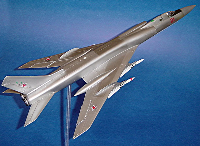
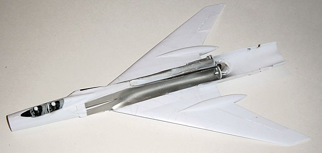
Tail Plane (Step 11)
Not
much to report here, except that for my money Parts 42 & 35 are the left
tail and 43 & 35 are the right tail, opposite of what is on the
instructions, unless they were designed to produce negative lift. Both
parts 42 & 43 have a somewhat irregular “wavy” shape on one side that
required more filling and sanding, as you can see from the Mr. Surfacer
stains on the accompanying photos. Also, the front rod on the tailplanes
will need to be trimmed way back to make them fit.
Nose Radome (Step 4)
I
delayed adding the radome, but there is no reason you really need to. I
was disappointed to discover that there is a small, but significant step
between the radome and fuselage. I used several applications of Mr.
Surfacer (as you can see from the photos) to overcome this. I probably
should have used a layer of putty first.
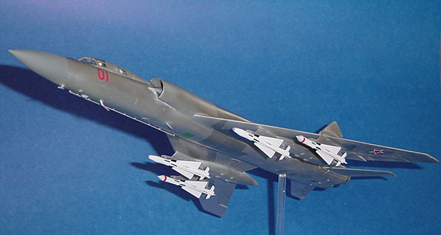
Missile Pylons (Step 13)
I
glued all the pylon pieces together before attaching them to the wing. The
outboard pylon/wing fence assemblies (Parts 36 & 37) fit well (finally,
something that did!) with only a little putty required at the leading edge
of the wing. However, the inboard pylons, which are “supposed” to fair
into the front of the landing gear pods, don’t. Quite a bit of grinding
off and test fitting was required to get everything to finally go together
correctly.
Clean Up
I started out
with 150 grit for major shaping, worked down to 600 to get things smoothed
out, finishing up with sanding pads, working down to 12,000 grit.
Then I primed the airframe with Halford’s primer, found a couple of spots
that needed a little more work and then worked from 600 back down to 12,
000 grit one final time.
Missiles (Step 13)
The
AA-5 “Ash” missiles have single piece bodies (Parts 98 & 99), which I
liked. What I wasn’t so keen on was that the separate wings (Parts 101)
weren’t quite as long as the ones molded into the bodies and that the
separate tail fins were of a different size not only from one another but
also the ones molded onto the bodies. Furthermore, they chose to attach
these small pieces to the sprue at the leading edge, so they ended up
being much thicker than they should have been! If you’re feeling really
industrious, you might want to cut your own tail fins out of plasticard.
(If Eduard does a photoetch set for this kit, they might want to think
about including the missile tail fins...) One other thing, the
instructions for locating the decals of what I believe are the proximity
fuzes are completely wrong. On the top and bottom of both missiles an
antenna “stripe” should be located between each set of wings with the
front of the decal about 1 mm behind the front point of the wing. On
either side of the missile, the fuze “stripe” should be in front of the
point of the wing. Also, the front portion of each wing even with the top
and bottom fuze stripes appears to be black (leaving a small (about 1mm
long) white triangle at the front of the wing). Finally, the conical
radome of the radar-guided variants appears to be a dirty white or light
gray.
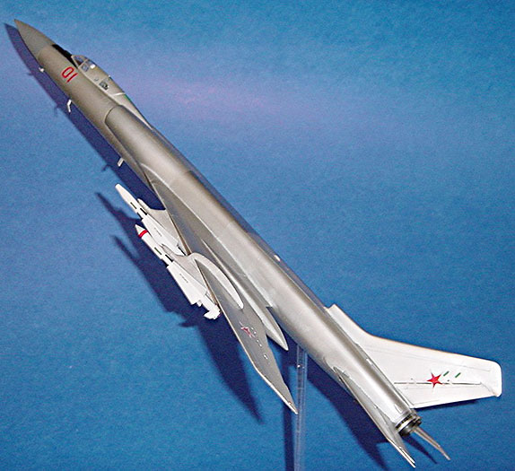
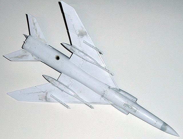
I finished the model using Alcad II Aluminum and Dark Aluminum and a wash
using Heavenly Hues to bring out some of the surviving panel lines (there
were a few!). The kit decals are nothing to write home about. First off,
they are flat, not good for a natural metal aircraft, so they have to be
gloss-coated. Also, the national insignia are surprisingly bad,
considering that the kit comes from part of the former USSR, being both
too large and with too big of white surround of the stars.
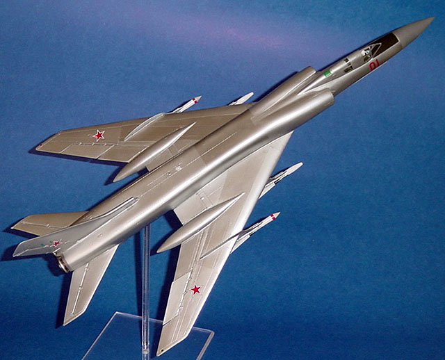
What I found to match up well with both available photos and the kit
instructions (!) were stars from the spare box that were 14 mm from
tip-to-tip. The kit instructions call for the Radome to be dark gray, but
the available photos I’ve found show it to be medium gray (I ended up
using Humbrol 164, which is BS 381C: 638 or 26173).
And this is what I do to relax?! Seriously, this may sound like a lot of
carping, but we aren’t likely to see a kit of this aircraft from Tamiya
anytime soon and I am tickled to have one in my collection. It looks like
a Fiddler (I’m not a micrometer kind of guy so will leave that to others)
and despite some obvious shortcomings, makes into a most impressive model.
Now, if A-Model will only do an accurate 1/72 T-22 Backfire C to replace
that clunky old ESCI kit...
Click the thumbnails below to view larger
images:
Model, Images and Text
Copyright © 2004 by
Jim Rotramel
Page Created 11 April, 2004
Last Updated
10 April, 2004
Back to
HyperScale Main Page |
 Home
| What's New |
Features |
Gallery |
Reviews |
Reference |
Forum |
Search
Home
| What's New |
Features |
Gallery |
Reviews |
Reference |
Forum |
Search