|
This is part two of a three part posting on my U-2S
"Senior Span/Spur" project. It has only taken two years
to get to this point. Sorry for the delay...
In part one I discussed a brief history of the U-2, a
description of the Testors / Italeri kits, and
the building of the fuselage on my U-2S model. In this
part I will discuss the completion of the fuselage,
construction of the wings, and attachment of the wings
to the fuselage.
Follow these links to get to the other parts of this
posting.
| |
Part
One: |
Aircraft History, Model Kit
Description, and Fuselage Interior Construction |
I left off in the last part with the fuselage having
just been assembled. That completed the work on the
inside of the fuselage. Now, there are lots of tings to
do on the outside of the fuselage.
Before installing the wheel bay unit into the
fuselage, I had cut the fuselage sides to open up the
engine intake areas. Into these openings, I could now
install the rear engine intake duct pieces. First, I
painted them following the instruction sheet directions.
The inner walls are colored with a color closely
resembling Israeli Pale Gray-Green (F.S.34242). I used
this color from the old Floquil Military Colors
line. Then, I gently pushed them into place inside the
engin eintake openings on either side of the fuselage.
The pieces are keyed to fit only one way. Scribing on
the pieces tells which piece goes on which side.
The fuselage update set completely replaces the
forward intake pieces in the kit with seamless one-piece
resin engine intakes. I painted the inside of the
intakes in the same Israeli Pale Gray-Green that I used
on the inner duct pieces, then I attached them to the
sides of the fuselage. They do not fit as well as I
would have hoped. Shrinkage in the resin causes htem to
be a bit small. I fixed this by applying a backing piece
of 0.015" sheet styrene on the sides that go against the
fuselage. This pushed the intake pieces out enough to
remove the step in the surface where the intakes meet
the fuselage.
When I constructed the the original intake master
pieces, I used the actual kit pieces as a starting
point. The result is that the new resin intake pieces
still have some of the original fit issues of the kit
pieces. I needed to fill voids on the top and bottom of
the pieces to achieve a flush surface with the fuselage.
I also needed to file down the mounting areas on the
fuselage sides because the intake pieces were too far
away from the fuselage (based on reference images).
The oil cooler louver details on the outside of the
intakes was another sticky point for me. My original
masters did not include these details. Considering the
nature of the louvers (being mostly flush), I considered
using a decal to represent them. As such, I only scribed
in the outline of the outer panel. The master pattern
maker at Meteor decided to help me and cut in the
louvers with some high-tech router milling machine.
Unfortunately, this person did not consult enough
references to get the louvers right (IMHO). They are too
big, too deep, and look more like grills than louvers
(IMHO). They are vast improvements on the louvers molded
on the kit intake pieces to be sure, but I wanted to
tone them down for my model.
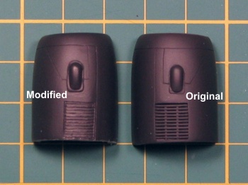
Corrected Intake Louver
|
I decided the only real way to do this was to start
over. I took a bunch of super glue and filled in the
louvers. Sanding this smooth, I re-scribed the panel
lines around the louvers. Next I measured and lightly
scribed the placement of the louvers and their
individual blades. Using a new X-Acto blade, I
scraped the lines so as to create the louver blades. It
took most of one night and a couple re-paintings with
primer to get to the point where I happier with the
louvers. The final version is seen in the picture to the
right contrasted with the louver as provided in the
Cutting Edge resin set.
My version of these
louvers is still not perfect. As they are hand carved,
there are some irregularities. They also are missing the
tabs on the louver blades that give the impression of
braces. But, I like my version better as they are much
less "in your face" on the finished model. When looking
at real U-2 aircraft, these louvers are mosty invisible
unless the lighting is just perfect to light up the
louver blades.
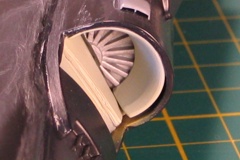
After working out the fit and permanently attaching
the intake pieces, I was very pleased with the view
looking in from the front of the engine intake. It is
not completely accurate (being a bit too shallow in
depth), but you would be hard pressed to see this on the
final model sitting on a display table.
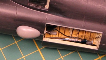
Inner Engine Intake Pieces |
Outer Engine Intake Pieces |
View from the Front |
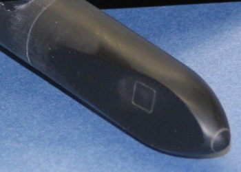
With the intakes
attached, I started test fitting the ASARS II nose.
There is a slight shrinkage when resin cures. To my
dismay, I found the nose was smaller in diameter than
the kit fuselage -- so much for expecting a "drop in
fit" with the nose. Rather than increasing the diameter
of the resin ASARS nose piece (which would have
necessitated some elaborate putty work to blend the
expansion into the rest of the nose), I chose to try to
reduce the diameter of the kit fuselage.
Helping me in this pursuit, I had someone in the UK
send me an e-mail telling me his ideas that the
Cutting Edge ASARS nose seemed to be too short based
on his investigations. I decided to take a much more
detailed look at the part using some side-view images to
measure the details of the nose. Bottom line, yes, the
nose is too short by somewhere between four and ten
scale inches. Also, the ADF fairing on the top is out of
place by a small amount and molded too large.
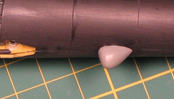
The ADF issues are hard to see without a tape
measure, so I ignored these, but the length of the nose
was noticeable to me, so I decided to fix it. I added a
1/8" adapter to the rear of the nose to lengthen it by a
scale six inches. This extention acted as an adapter and
gave me the chance to start to enlarge the nose diameter
to better meet the size of the kit fuselage. I then
filed down the forward 1/8" of the fuselage to reduce
its diameter to meet the size of the nose piece.
Fortuneately, the thickness of the fuselage pieces is
sufficient so as to allow this thinning without breaking
through.
Effectively, this process slightly decreased the
cross-section of the fuselage, nominally increased the
forward fuselage taper, and lengthened the nose, but it
made everything meet up without having to blend a lot of
putty on the nose itself. I glued the nose into place
and addressed the seams where it met the reduced
diameter fuselage. There are a couple small blisters on
each side of the fuselage just behind the nose joint
that seem to only be on ASARS equipped aircraft. I
whipped up the blister shapes using some strip styrene
and attached them in place.
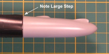
The Fit of the ASARS Nose
Before Fixing It |
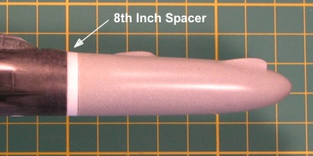
The Fit of the ASARS Nose
After Fixing It |
The Italeri
horizontal tails have some fine ribs molded onto the
upper leading edges. After some investigation, I found
these only pertain to early-built aircraft (serial
numbers 68-10329 thru 68-10340). The ribs are stiffeners
to solve a flutter issue when the super pods were added
to the wings. Later-built aircraft (serial numbers
80-1063 thru 80-1099), do not have these ribs. To solve
the flutter issue, the later airframes had the interior
structure beefed up when they were constructed.
If building a model of an early-built aircraft, leave
the kit-provided ribs on the tails. If building a model
of a later-built aircraft, remove the ribs. Here is the
problem, though -- the ribs should be on both the top
and bottom of the tails. The kit only has them on
the top.
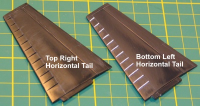
Horizontal Tail Ribs
|
The original aircraft I saw at the Andrews AFB air show
was a later-built aircraft without the ribs on the
horizontal tails. However, I really liked the look of
the ribs on the kit tail and decided to change the tail
number on my model to be an early-built aircraft with
the ribs. This meant I had to scratch-build the ribs on
the lower sides of the tails. I did this with 0.010" by
0.030" strip styrene. I rough-cut the taper into the
strip, tacked it to the tail, chopped it to the right
length, and permanently glued the rib. My results are
show here to the right.
For any modelers
considereing whether they need these ribbed tails, for
what it is worth, I learned from looking over a U-2
aircraft attrition table that most all the early U-2R
airframes have been lost for one reason or another. Most
any U-2 seen today is a later-built aircraft that will
not have the reinforcing ribs on the horizontal tails.
All the ER-2 aircraft flown by NASA and the two-seat
U-2R/S aircraft are also later-built aircraft without
the ribs.
To help other modelers wanting ribbed horizontal
tails, I provided my modified tail pieces to Meteor
Productions. The recently released U-2 horizontal tails
correction set is made from my masters. I actually used
Cutting Edge pieces on my model, here, not
modified kit pieces.
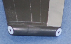
The vertical tail on the U-2 is sort-of unique,
especially in the way it handles trimming the aircraft.
Instead of (or in addition to?) standard trim tabs on
the horizontal tails, the entire unit formed by the
vertical and horizontal tails is one solid item that is
pivoted inside the fuselage to accomplish trimming the
aircraft. The thin white or silver line on the leading
lower vertical tail is one scuff zone for this unit when
it pivots.
Another scuff zone exists all along the lower edge of
the vertical tail where the tail slides in and out of
the rear fuselage. This scuff zone is black though,
instead of the white or silver found at the leading
edge, so it is easy to miss on a casual look, but it is
there. A glove fairing at the base of the rudder that
produces a small step in the surface is part of this
scuff area. I wanted to include this fairing on my model
and added it using some 0.010" sheet styrene.
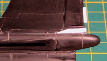
Vertical Tail Scuff-Zone |
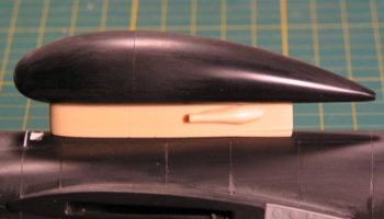
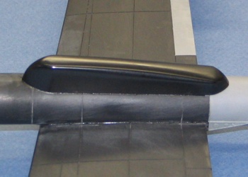
Senior Span/Spur Dorsal
Antenna Unit |
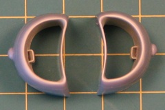
The next thing I worked
on was the bulbous Senior Span/Spur dorsal antenna.
Comparing the Cutting Edge pieces to the recent
Italeri U-2S pieces, I found I liked the
Italeri antenna pod better, but I preferred the
Cutting Edge antenna pylon. I cleaned up the
Cutting Edge antenna pylon pieces and attached the
piece for the large cooling intake found on the left
side of the antenna pylon. Then, I assembled the
Italeri antenna pod and hacked it off of its pylon.
After cleaning up the seams, I attached it to the
Cutting Edge antenna pylon. I attached the unit to
the fuselage with brass wire pins to make sure it was
secure.
Choosing to use the Cutting Edge dorsal
antenna pylon opened a can of worms for me. The pylon
has recessed scribing while the Italeri kit has
raised. I hate when all the components of a model do not
match on this detail. I toyed briefly with the thought
of adding raised scribing to the Cutting Edge
piece, but decided against it. Instead, I broke out my
scribing tools and rescribed the rest of the model to
match the recessed lines of the Cutting Edge
piece. Since the majority of the lines are just long
straight runs, this was not as difficult as it can be on
some other aircraft.
At this point, I was down to minor things on the
fusleage. I added mounting plates and drilled holes for
the anti-collision beacon lights that are provided in
the Cutting Edge fuselage update set. I would add
the lights after I was done painting.
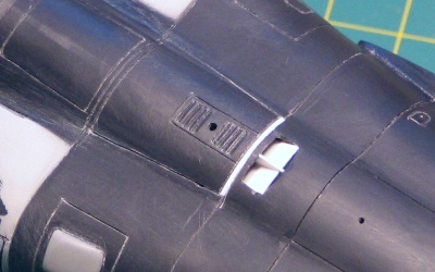
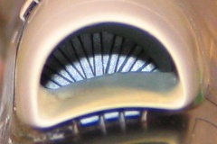
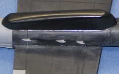
Spine Exhaust Port
|
The kit has several molded-in louvers on the upper
fuselage. These are way over-done, represented as deep
depressions with some molded ribbing. I took a moment to
fill most of them in with super glue and sand them
smooth. The louvers molded over the wing roots are only
applicable to U-2R aircraft with the J75 engine. The
aircraft lost these louvers when they were upgraded to
the U-2S standard and received a TF118 engine. Since it
was a U-2S that I was building, I just filled these and
left them go.
The louver on the
aircraft spine, just ahead of the Senior Span/Spur
antenna pylon, is not a louver at all on the real
aircraft. It is an open exhaust vent for the hot air
exiting the air conditioning unit behind the cockpit. I
drilled this vent open and added some sheet styrene to
create the angled forward slope of the vent. In front of
this exhaust are a couple louvers that bracket the
location of the upper communications blade antenna. I
used an X-acto knife to scrape thes in like I did
for the louvers on the sides of the engine intakes.
Under the forward and rear fusleage, there are two
data link antennae bulges on the U-2. Over time, these
antennae have varied in shape and size. Sometimes they
are not even installed. Looking at reference pictures, I
determined that the aircraft I was building used the
more common types of these data link antennae. The
needed bulges are provided in the Cutting Edge
fuselage update set. I cleaned them up and attached them
to the fuselage.
Forward Data Link Antenna
Bulge |
Rear Data Link Antenna Bulge |
The last thing I
addressed on the fuselage was to drill a bunch of
locator holes in the lower center fuselage. These holes
would be the locators for the antennae farm found on the
bottom of Senior Spear aircraft. The Cutting Edge
Senior Span/Spur/Spear update set and the Italeri
"Senior Span" kit both provide all these antennae as
well as instructions on where they all go.
With the fuselage mostly assembled, it was time to
turn my attentions to the wings. Many pictures of parked
U-2 aircraft show the wing flaps being down, although
the one I saw at the Andrews AFB air show had its wing
flaps up. This left me with a quandary -- do I drop the
flaps or not? I decided to have the flaps dropped.
Besides the look of the model with its flaps down, this
would also give me a chance to correct some fit issues
on the wings. There is a substantial seam on the wing
top that cuts straight through the flaps. Replacing the
wing flaps removes this wing seam when the kit's wing
flaps are cut off.
I used the Cutting Edge U-2R/S / TR-1 Wing
Correction set. Having created the masters for this set,
there were no surprises in its usage. Not only does the
set provide dropped wing flaps, it also provides
replacement super pod tail cones, corrected antenna
fairings, and properly sized ailerons along with some
other minor details.
I started by cutting the wing flaps and ailerons off
of the kit wings. I then measured the distances
carefully to where various items should be located and
further cut the wings to make these details line up
correctly. The exact measurements are outlined in the
Cutting Edge instructions.
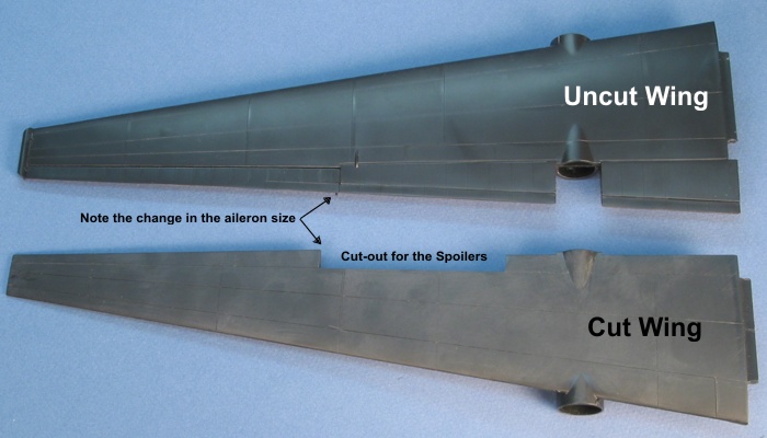
Cut and Uncut Wings |
Before I assembled the
wings and started attaching the correction set pieces to
the wing, I took time to re-scribe the wings to engraved
scribing. As it was all just long straight runs, this
was done easily with a metal ruller and an X-acto #11
blade drawn backwards over the wing surface. A few of
the kit scribed lines are located in the wrong place, so
I also took time to measure out the corrected locations
and scribe the lines. Most notable amoung the incorrct
lines are the wing fold lines. They should be 70 inches
from the wing tip. Italeri molded them about a
scale foot (a quarter inch) too far inboard.
Assuming the wings are cut correctly, the resin
pieces attached to the wing easily. I missed by a little
on one of the spoiler wells and had to add a strip of
styrene to fill a gap that I created by accident. The
instructions say "measure twice, cut once", but I always
get too excited to take time to be that thorough. I
permanently attached the super pod tail cones, spoiler
wells, System 20 and GPS fairings, and the ailerons. I
left the wing flaps loose until after doing some
painting. With the mounting tabs on the flaps, they hold
themselves into place quite well, so I could get the
look of the wings without committing glue to the flaps.
There is one quick fix to make on the resin wing
pieces. When I made the masters, I accidentally scribed
some bad lines on the outboard flaps. I thought I had
sufficiently filled in the bad lines, but in the resin
pieces you can still see the hint of them. Note the
pointer in the one image below and remove all traces of
the line being pointed to in the pictures. The same line
is present on both sides of both outboard flaps.
Sorry...
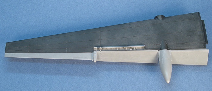
Wing Flaps Installed |
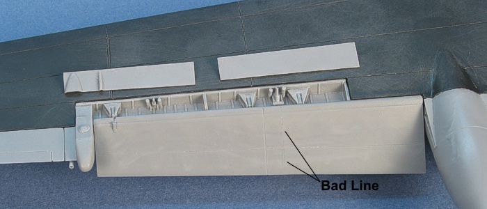
Wing Correction Detail |
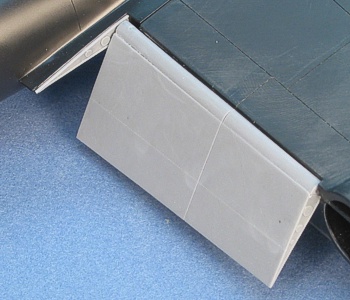
Flap Angle Detail
|
Next, I turned my attention to work on the super pods.
In the "Sky Patrol" kit, the super pods are simple tubes
with rounded cones that fit on the front and rear of
each wing-mounted center section. There are no bulges or
antennae provided. In the "Senior Span" kit, the nose
cones of the super pods are modified to incorporate the
flattened sides of the Senior Ruby installation and the
canoe fairing for the left super pod is included for the
Senior Spear installation.
Wanting to have my model
outfitted with both Senior Spear and Senior Ruby
(collectively referred to as Senior Glass), I built up
the Senior Ruby nose cones for the super pods and
attached them to the wings, orientating the flat spots
at a slight angle down from facing straight out to the
sides. I studied all the pictures I could find and
decided to use the Italeri kit canoe fairing
under the left super pod. I am not convinced that its
shape is any better or worse than the Cutting Edge
equivalent piece, it is just different. The selling
feature for me was that the kit canoe fairing fit better
onto the super pod.
Senior Ruby Super Pod Nose |
Senior Spear Super Pod Canoe |
Then, I addressed the
seams where the super pod nose cones are attached. With
a little pre-work to flatten out the mating surfaces,
the cones mounted with only a small seam. I filled this
and sanded it smooth. Then, I turned right around and
scribed a panel line right where the seam line had been.
I continued on to scribe lines around the super pods
based on the diagram in the Cutting Edge Senior
Spear/Span instructions. With the scribing done, I
located and drilled holes along the pod centerlines to
mount the Senior Spear blade antennae.
The last details I added to the super pods where a
series of small intake vents along the outside of each
pod. These are provided in the Cutting Edge wing
correction set. There are three intakes on the left pod
and two on the right. Shrouded in shadows under the
wings, I did not even know these intakes existed before
I started researching to create the wing correct set
masters. Some pictures I got from a source on the
Internet highlighted them to me. Knowing about them, I
was then able to find them in my own pictures, too. It
is amazing how long you can look at some pictures and
not see some details.
The wingtip skids from the kit are fine. I cut these
from their sprue and attached them on the wingtips. The
ECM pods that attach to the skids are also pretty much
fine right out of the kit. I did add some laminated
sheet styrene to their end plates with punched out holes
to represent the round center antenna points, then
attached the pods to the skids. I also filed off the
solid kit navigation lights and drilled holes to mount
Cutting Edge clear red/green lenses from the
generic Cutting Edge navigation light sets.
With the wingtips done, I moved to the undersides of
the wings. First thing here is to change the location of
the pogo leg mounting holes. Italeri molds the
holes too far inboard. They stay within the same
scribing panel, but move outboard to the outer edge of
the panel. Picturtes show what looks like a reinforcing
plate where the pogo legs attach, so I built this up
using 0.005" sheet styrene. Then I drilled the mounting
holes for the pogos.
The final additions to the wings were the fuel cell
pressurization intakes. These small scoops are found in
the lower middle of the wings, just inboard of the
attachment points for the pogo legs. These are also
provded in the Cutting Edge wing correction set.
Super Pod Vents |
Wingtip |
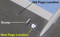
Fuel Cell Pressurization Scoop |
With all these wing
modifications complete, it was time to rent a gymnasium
to hold the fully constructed model. Thus, I started the
process to attach the wings to the fuselage.
As I was dry fitting the wings to the fuselage, I
came to the realization that the wing joint was going to
be a weak point in the model. And, the lowered wing
flaps had decreased the size of the mounting area for
the wings. There is more than twelve inches of wing
hanging off each side of the fuselage. Those long wings
have relatively small mounting areas with their locating
tabs being rather short (in comparison to the overall
length of the wings). Even if I did manage to firmly
attach the wings to the fuselage, the weight of the
wings hanging on the model could potentially split open
the upper fuselage seam. I decided I wanted to add a
length of brass tube as a wing spar to add strength to
this joint. This would also help to align the wings for
attaching them and keep them aligned after they were
attached.

Wing Spar Modification |
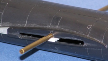
Fuselage with Wing Spar |
To start the process, I
measured and cut away a center portion of the wing
locator tab on each wing. I then drilled an appropriate
sized hole (1/8th inch)
in the wing inner edge at the place where I had removed
the locator tab section. It was important that these
holes in the wings would line up with each other so the
spar would fit straight across from one wing to the
other.
With the wings modified, I then measured the fuselage
to locate the correct positions of the holes to pass the
wing spar though. Drilling more holes in these locations
on the fuselage set up the whole assembly to be
completed. I measured the brass tube to determine how
far into each wing I needed the spar to go, then cut it
to the determined length (5 inches). This provided about
an inch and one half of spar sticking into each wing.
That seemed enough to me. After making sure the spar was
level in the fuselage and that the wings fit as I
wanted, I super glued it in place on the fuselage. I
then slipped the wings on for a final check. With
everything lining up the way I wanted, I glued the wings
to the fuselage.
I reworked and modified many more places on the model
than I thought I would at the beginning of the project.
The picture below shows the model just before I painted
it. With the black plastic of the original kit, all the
modifications in white plastic and gray/beige resin
stand out quite well.
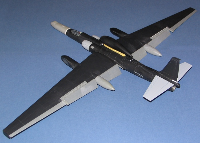
Assembled Model Before
Painting |
This completed the
airframe construction. Time for painting. As the
descriptions have gone on here long enough, I decided to
break here and have the painting and finishing of the
kit be a third part in my U-2S "Senior Span/Spur"
project postings.
(Newest to Oldest)
-
U-2R/S Walk Around
by David W Aungst
On-Line HyperScale Reference, 2003
-
U-2: The Second
Generation by Chris Pocock
World Airpower Journal, Volume 28, AirTime
Publishing, 1997
-
Dragon Lady by
Ted Carlson / Toyokazu Matsuzaki
Koku-Fan Magazine, Volume 1996-04, Bunrin-Do
Company, Limited, 1996
-
Recce Tech by
Paul F Crickmore
Osprey Color Series, Osprey Aerospace Publishing,
1989
-
U-2 Spyplane in
Action by Larry Davis
, Squadron In Action #86, Squadron Publishing,
1988/2002
-
Lockheed U-2R/TR-1
by Jay Miller
AeroFax MiniGraph #28, AeroFax, Inc., 1988
-
Lockheed U-2
by Jay Miller
AeroFax AeroGraph #3, AeroFax, Inc., 1983
|
 Home
| What's New |
Features |
Gallery |
Reviews |
Reference |
Forum |
Search
Home
| What's New |
Features |
Gallery |
Reviews |
Reference |
Forum |
Search