|
Revell's 1/72 scale U-Boat
Typ VII C U-552 (late)
by Don Jamieson
|
 |
|
U-Boot Typ VII C |
images by Brett Green

Revell's
1/72 scale U-Boat Type VII C is available online from Squadron
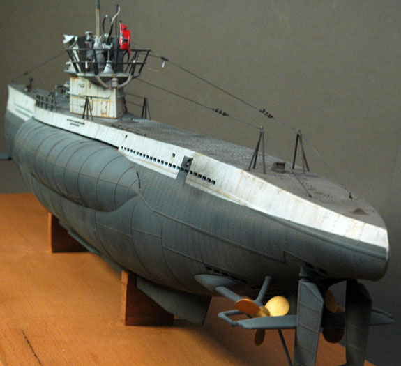
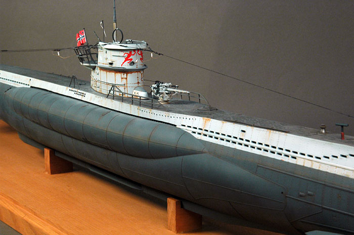
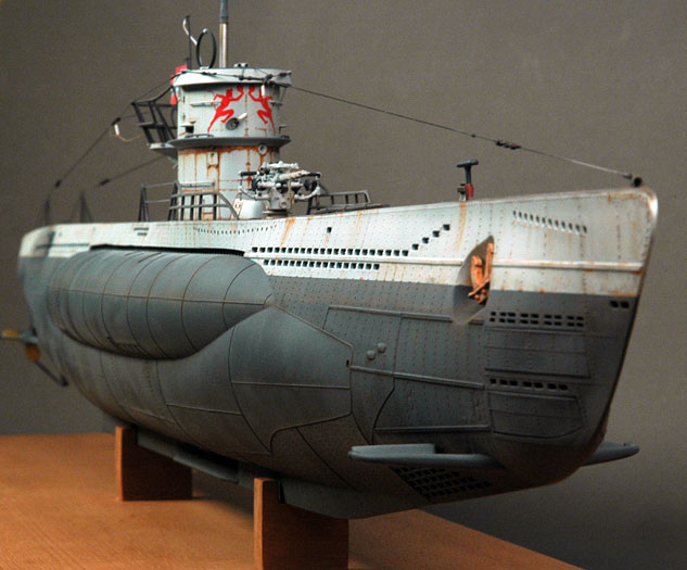
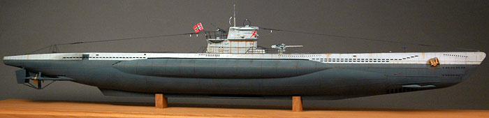
Here is Revell's 1/72
scale Type VII C U Boat.
I finally had the chance to devote some attention to this fantastic kit.
It is big and does take up a lot of space especially when you add a
solid Tasmanian Oak base “That weighs a ton”.
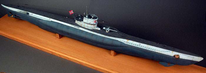
The model out of the box is quite acceptable but I spent many hours of
research, scratch building and general assembly to do justice to the
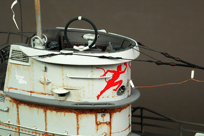
U-Boat I was representing. I had an interest in U552 because of its
colourful markings on the conning tower and one of its most notable
“Skippers”, KptLt Eric Topp and early on decided to build the late
version of this boat. I broke the assembly down into subsections for
ease of completion. The main areas on which I concentrated are
highlighted in this article.
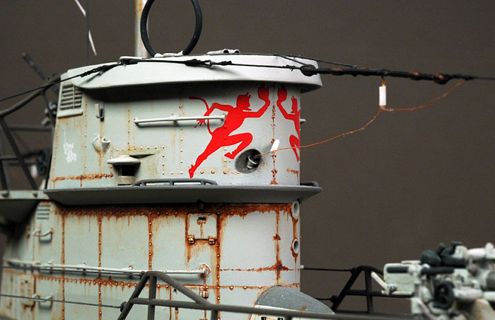
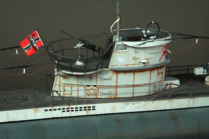
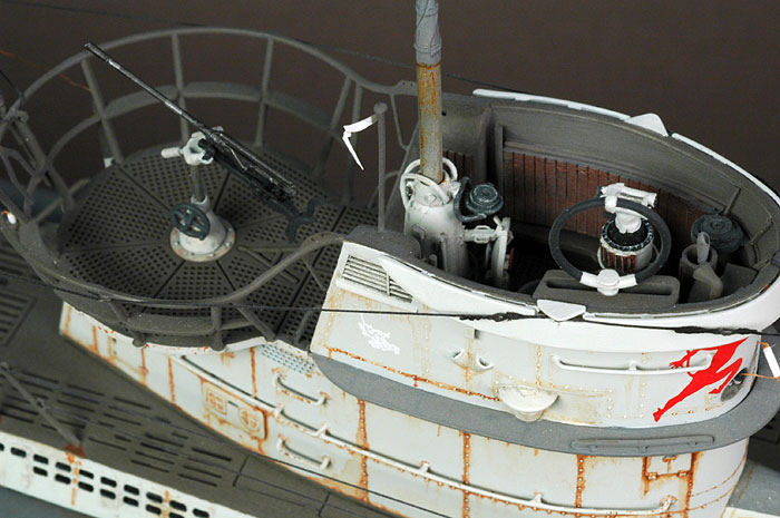
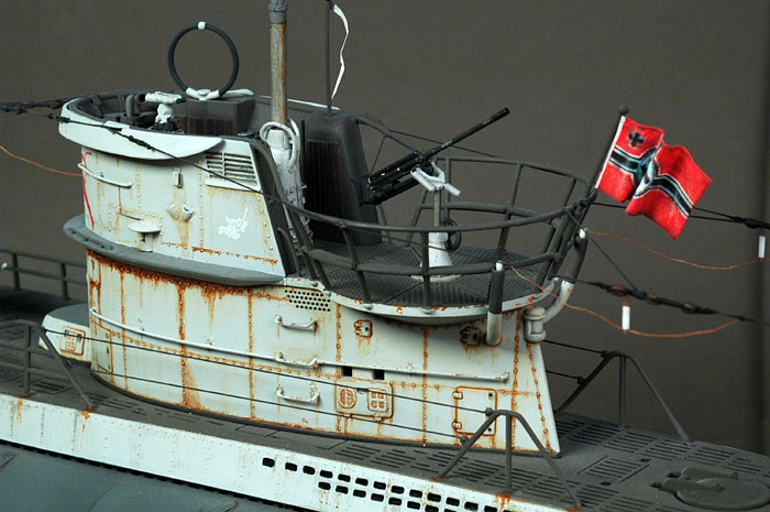
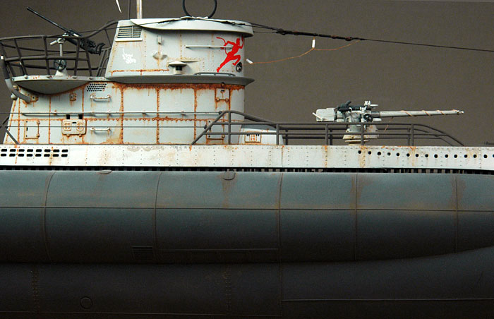
Conning Tower
This was assembled in
two parts, upper and lower. All rails were replaced with brass wire.
Following reference photos, the lower portion aft on both sides had the
access hatches opened up and lowered below the railings. An additional
hatch was positioned below these on which the circle and square with
cross markings were hand painted with thick paint to provide that welded
relief look. I had been informed these were markings for compressed air
and oxygen. This same method was used on the magnetic compass fairing.
The “horns” which carry the receiving aerial wires at the aft edge of
the conning tower that extend up to the wintergarten rails was made from
plastic tube which had wire stiffeners placed inside.
The two indentations on the forward port lower side almost at the
centreline were, I am told foghorns. These were opened up and configured
to look like the references.
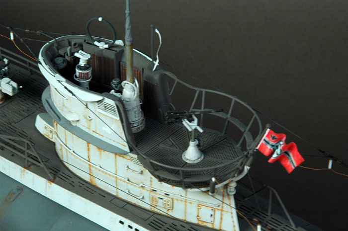
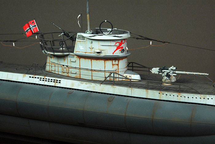
The upper section was the most challenging. The periscope fairing was
lengthened and detailed including the missing compass. The main
periscope was thinned down and a set of cables was fixed to the upper
part. These apparently broke the water flow into general turbulence
(something to do with harmonic frequencies, causing vibration and in
some cases, structural failure as the long unsupported piece of the
periscope moved through the water). “It’s an engineering kind of thing”.
The UZO was rebuilt as it was undersized and when completed, a
scratchbuilt pair of binoculars was positioned on top.
The main hatch received inner detail in the form of locking lugs and a
wheel. The open hatchway has a ladder down to the internal conning tower
space. The voice pipe was repositioned higher onto the shelf below the
lip of the forward conning tower starboard side. The kit-supplied shelf
(part 54) was halved and a compass was positioned portside where the
other half of the shelf would have gone. According to my references,
below this, the kit part (part 56) that I believe is an engine repeater
was detailed and placed slightly more aft.
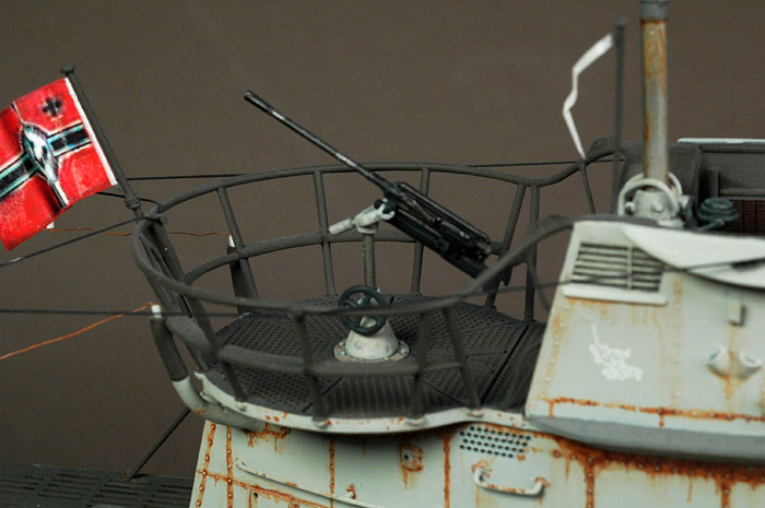
The 20mm cannon was detailed with new shoulder braces, as mine were
broken beyond repair. A sight was also added. The shaft on which it sits
is brass tubing. The wintergarten railings are the kits but were
repositioned so that they blended with the bridge wings. Brackets were
added to represent the part of the mounting points for the
torpedo-loading frame. Various other items were added to dress up this
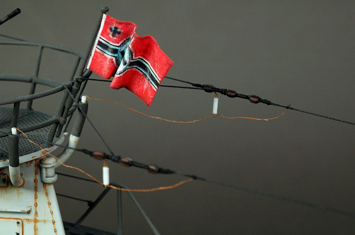
area. The Flagpole was made from brass rod. The flag was printed on a
laser jet printer and replaced the kit flag which apart from not having
swastikas, looked generally wrong. A Commanders flagpole was made
including the pennant and positioned on the starboard side on the
ventilation trunk.
8.8cm Deck Gun
The 8.8cm deck gun is
another viewing attraction of this kit which is ok in its supplied form
but can be further improved for accuracy. All my kit supplied crew
braces were broken so I replaced them with brass rod and insulation
material from wires. They were then correctly formed and placed in the
stowed position.
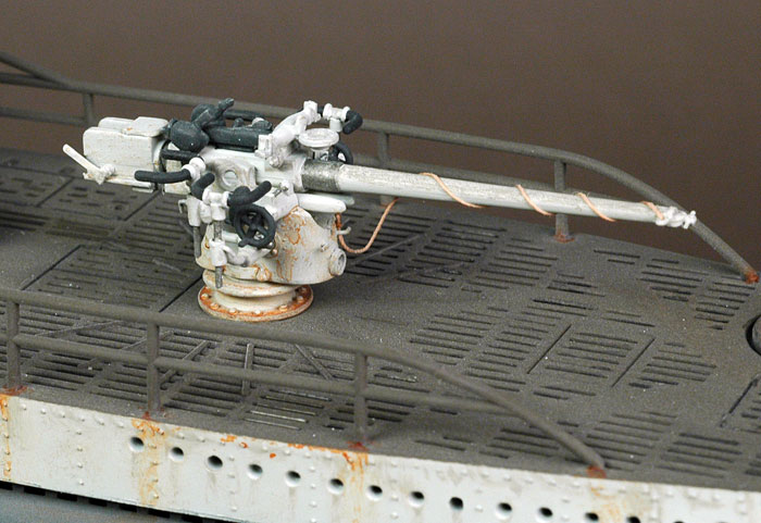
Various other bits were
added to the gun and base including a receptacle for the gun tompion.
The tompion on the end of the kit barrel was further detailed and a
lanyard made from tan quilting thread was applied.
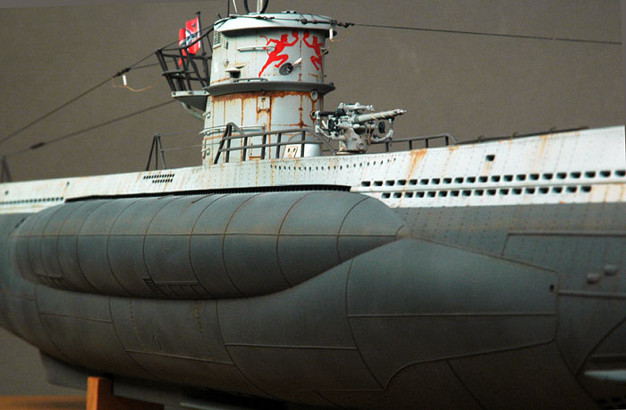
The Hull
I drilled out the many
flood holes by hand using a pin vice with a drill bit and cleaned up
with a scalpel and files. No, I don’t own a Dremel power tool. It really
wasn’t a hassle (quite therapeutic really) and they were less than the
thousands of portholes I drilled out for my Titanic model. I paid
careful attention to the known copies of photos that I had of U 552 to
ensure that I could best represent the right pattern and in some cases
had to add, delete and reposition them. The long indentation along the
top of the saddle tanks were recessed floodholes. I cut out and backed
this area with spaced square plastic rod to represent the floodhole
pattern. The extreme bow holes were repositioned and the correct number
was made two to starboard and three to port.
All this as on the real boat would allow light to show through from the
deck and sides. This did pose a problem. I made sections of the inner
pressure hull and some details like the torpedo stowage canisters from
rolled card paper and various bits of plastic tubing and strip. These
were then sprayed with a very dark grey and give this area some sense of
depth and internal structure. The bow tow hole was made bigger.
Some may question the position of the anchor being too close to the
forward hydroplane fairing. In its present position, the skipper would
be very upset if when going to anchor, they dropped the “pick” on the
hydroplane fairing. I thought about moving it and also considered moving
the hydroplanes aft a bit, but decided that I had done enough surgery on
the hull.
Rigging
To represent the wires
fore and aft on the boat, I used 3/0-and 4/0 gauge surgical braided silk
and incorporated this into the kit parts.
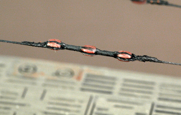
Some couplings
particularly around the conning tower where the cable runs were made
from wire. The lead in and out wires to these are fine copper wire on
scratch built insulators.
Boy, is this a hot topic
for U-boat fans. I used various mixes of Tamiya and Gunze acrylic paints
and weathered the kit based on the copies of photos I had. Weathering
was done with pastels, washes and airbrush streaking.
As mentioned before, the completed boat was mounted on a piece of solid
Tasmanian oak. It has a 3mm routed edge to take a clear acrylic case.
I thoroughly enjoyed
building this kit and it has pride of place in my home. It took many
months to complete due to time constraints and the need to check
reference material to detail and fashion replacement parts. I hope you
enjoy the photos.
Click the
thumbnails below to view larger images:
Kriegsmarine U-boats
1939–45 (1)
New Vanguard 51 |
|
|
|
|
Author: Gordon Williamson
Illustrator: Ian Palmer
US Price: $14.95
UK Price: £8.99
Publisher:
Osprey Publishing
Publish Date:
May 25, 2002
Details: 48 pages; ISBN: 1841763632 |
|
|
Model and Text by Copyright ©
2005 Don Jamieson
Images Copyright © 2005 by
Brett Green
Page Created 22 October, 2005
Last Updated
24 October, 2005
Back to
HyperScale Main Page |
 Home
| What's New |
Features |
Gallery |
Reviews |
Reference |
Forum |
Search
Home
| What's New |
Features |
Gallery |
Reviews |
Reference |
Forum |
Search