|
Scratchbuilt 1/32 Scale
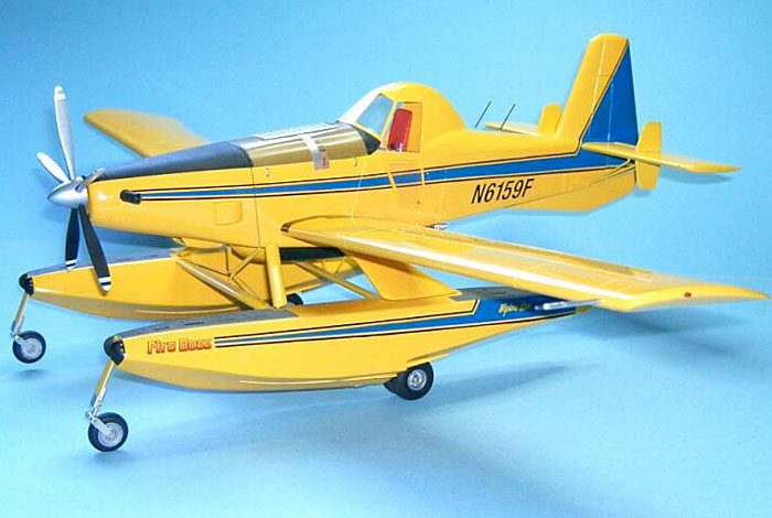
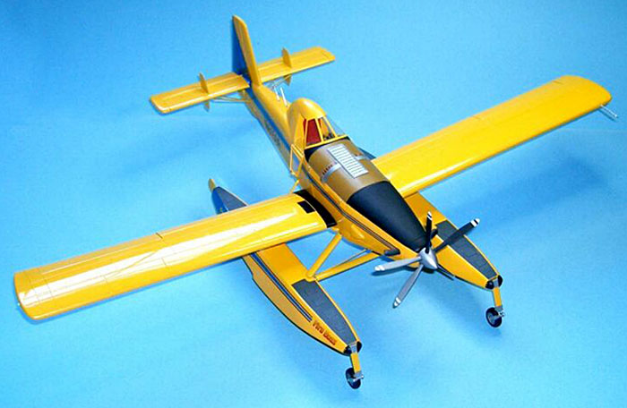
Wipaire Fire Boss
by Dr Frank Mitchell
|
|
|
Wipaire Fire Boss
|

HyperScale is proudly supported by
Squadron.com
We sometimes get into models in strange ways.
For example, I was idly looking over the magazines at
my friendly Barnes and Noble when I spotted this airplane on the cover of
Canadian Aviation. 10 seconds later I had decided to build one in 32nd
scale.
Thanks to some very kind people at the float manufacturer and the Canadian
representative, I was able to obtain drawings and information on the
floats, and, along with some more data gathered on the Internet, there was
enough to begin.
Before I go into construction, however, I guess I
ought to describe the aircraft.
The Airplane:
The Wipaire Fire Boss is a quick response
fire-suppression aircraft with an 820-gallon maximum hopper capacity. The
airframe is an Air Tractor AT-802 agricultural aircraft. It is powered by
a P&W PT6A turbine engine and has a span of 58 feet and length of 35 ¾
feet, making for a 1/32nd scale span of about 22 inches.
Not a small airplane.
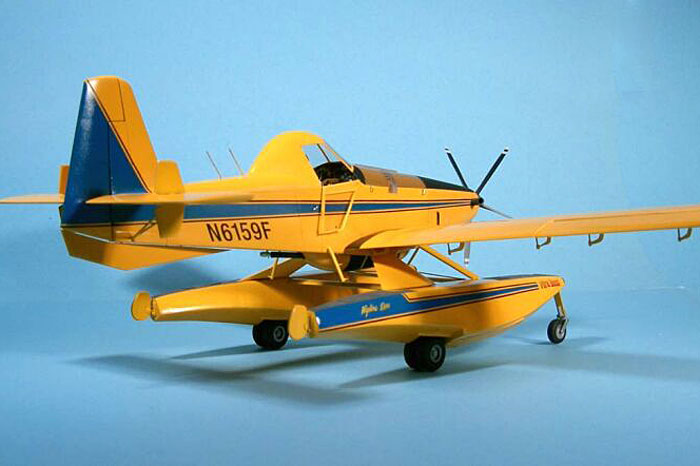
The floats and fire-fighting equipment are added by Wipaire, Inc., in St.
Paul, MN. Since it is an amphibian, the aircraft can operate as a
land-based tanker or, using scoops built into the bottom of the floats, it
can pick up water by skimming the surface of nearby lakes and rivers,
which would seem to be an interesting technique to learn.
I have attached a number of “in-construction” photos,
so feel free to watch the bouncing ball.
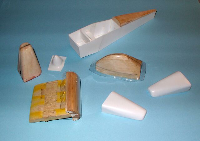
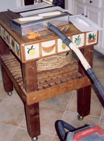 The
first step of construction was to carve molds for the floats, wings, tail,
canopy, and engine/nose. These were vacuum-formed using my old
tried-and-true techniques (see photo at right). The
first step of construction was to carve molds for the floats, wings, tail,
canopy, and engine/nose. These were vacuum-formed using my old
tried-and-true techniques (see photo at right).
The molded floats were cut out and formers installed, leaving suitable
openings for the wheel wells and trying to maintain sharp edges where
possible. I also tried to make sure to add a former or some other support
for the float struts and landing gear mounts.
Click the
thumbnails below to view larger images:
The main part of the fuselage (from the engine back)
was built up using 60 thou sheet styrene, with attention given to making
it as square and straight as possible. A wood block was added to the top
rear and sanded to shape.
The fitting the floats to the fuselage was fiddly
because of trying to make sure that everything was square and reasonably
sturdy. The rear struts are large faired shapes which also contain the
water uptake pipes, so each of them were made using a brass wire skeleton
with a wooden fairing around the struts. The visible portion of the uptake
pipes were made from plastic tubing. All-in-all, lots of trial and error
in this area since I couldn’t come up with a jig that wouldn’t get in the
way, while trying to keep everything unglued for painting and finishing.
Nobody said it would be easy.
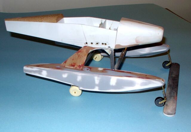
The landing gear was made from brass and aluminum tubing (main) and brass
sheet/tubing (nose), along with a bit of soldering. The wheels were resin
copies of a couple of wheels from the scrap box using a RTV molds.
The two molded halves of the nose were glued onto the balsa molds (for
strength and to make mounting it and the prop easier). The nose was
cleaned up and keyed to the main fuselage with two pieces of aluminum
tubing. Several scoops and vents were molded over balsa forms and keyed to
the cowling with brass wire. A spinner was turned from acrylic rod, while
the prop blades were made by cutting the basic shape from sheet styrene
and then adding half-round strip to the lower section. This was all
covered with epoxy and sanded to the proper shape. They were then keyed to
the spinner using brass wire.
Click the
thumbnails below to view larger images:
The exhaust stacks were made from
styrene tubing bent using tube benders and a bit of heat.
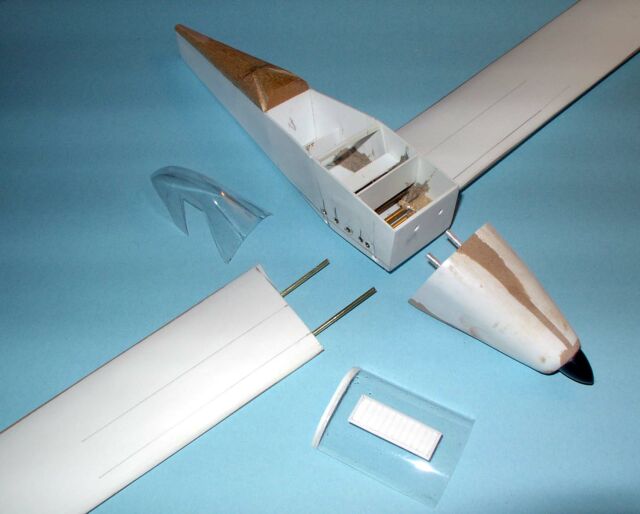
The wings were made by gluing (epoxy) the molded wing skins to the balsa
molds. The fuselage was prepared for the wings by drilling holes through
the structure and supergluing brass tubes that would receive smaller tubes
mounted in the wings. The reason I went to that trouble was that the wings
are rather long, and I needed all the strength I could get.
The tail was made in the same way as the wings, but supporting struts for
the stabilizer were made from brass wire and the small stabilizer and
under-fuselage fins were cut from styrene sheet.
All the control surfaces were cut out and re-mounted with brass pins.
The actuators for the ailerons/flaps consist of arms cut from brass sheet,
which were then soldered to a piece of brass rod (a photo helps to make
sense of that). This was then cut between each arm. They were mounted in
the wing by supergluing the pointed ends into small slots cut in the
appropriate places on the bottom of the wings. Brass wire was run through
the small pieces of tubing into the control surfaces.
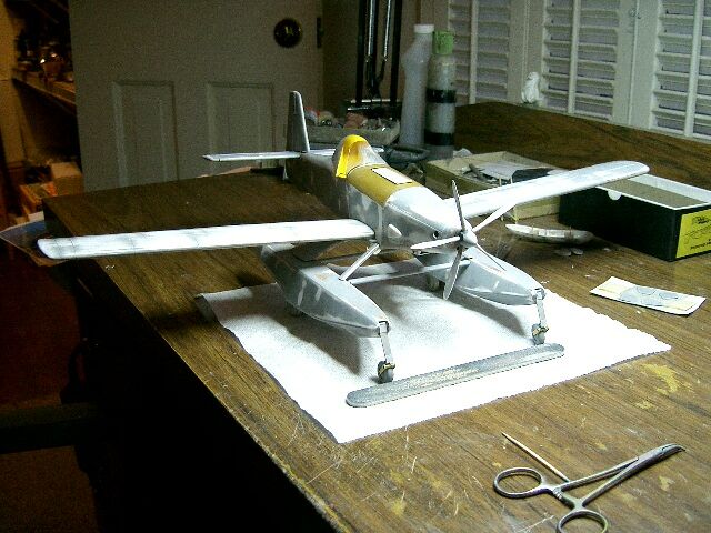
When taped together, the model and revealed itself to
be a confirmed tail-sitter. That was fixed by drilling a couple of ¼”
holes into the balsa core of the engine, and dropping into each of them
several lead fishing weights. A drop of superglue was dropped down the
hole to keep everything in place.
The top of the main tank was clear 1/32nd plexiglass molded over a balsa
form which was trimmed to fit the fuselage and the nose. There is a large
vent in the top of the tank to allow over-fill to escape when scooping
water. That was made from styrene; a matching hole was cut into the tank
top. To get the look I was after, a bit of yellow paint was mixed with
brown and thinned probably 80%. A light coat of this was sprayed inside
the cover. The point was to make the tank top semi-translucent. The tank
interior was sprayed flat black.
The canopy was trimmed and sanded to fit the rear fuselage and the water
tank, and the interior was detailed in all the usual ways.
At this point, all the parts were primed and sanded (several times) using
automotive lacquer primer. When I was satisfied with the surface, the
pieces were scribed as necessary. Mercifully, there wasn’t all that much
on this airplane.
Now came the painting process. This is a fairly large
model, and it is essentially all gloss yellow, not the easiest color to
work with.
 The
first coat of paint was Testor’s semi-gloss white. Although it covers
reasonably well, I really didn’t try to make it flawless. The yellow was
also by Testor but was the little square jars of enamel that have been
around for a hundred years. I still think it has the finest pigment and is
the best there is for gloss (and a lot of flat) paints. In this case, I
mixed two bottles of gloss yellow with one bottle of flat yellow along
with some lacquer thinner (I wanted a slightly flat surface because of the
masking that had to be done). I shot three coats of yellow at one sitting,
then two more the next day, adding maybe a half bottle more of the gloss
to even-out the thin areas. By using several coats, there was a minimum of
lost detail. The bottom line is that white and yellow, particularly gloss,
can try one’s patience, and the only solution is several thin coats,
giving each ample time to dry. The
first coat of paint was Testor’s semi-gloss white. Although it covers
reasonably well, I really didn’t try to make it flawless. The yellow was
also by Testor but was the little square jars of enamel that have been
around for a hundred years. I still think it has the finest pigment and is
the best there is for gloss (and a lot of flat) paints. In this case, I
mixed two bottles of gloss yellow with one bottle of flat yellow along
with some lacquer thinner (I wanted a slightly flat surface because of the
masking that had to be done). I shot three coats of yellow at one sitting,
then two more the next day, adding maybe a half bottle more of the gloss
to even-out the thin areas. By using several coats, there was a minimum of
lost detail. The bottom line is that white and yellow, particularly gloss,
can try one’s patience, and the only solution is several thin coats,
giving each ample time to dry.
The next step was the blue and black trim, and for
this, I needed several yards of drafting tape. One of those
three-hours-to-mask-and-thirty-seconds-to-spray situations.
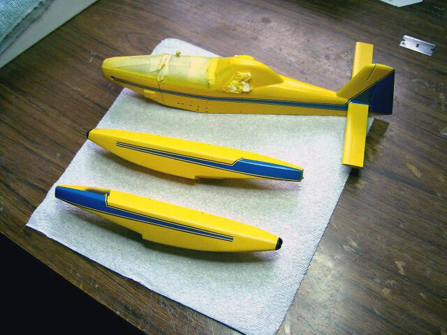
When that was done, I shot a coat of Future to
achieve the high gloss I wanted. From all the pictures I have, these
aircraft appear to be kept in pristine condition, so there was no
weathering applied.
The decals were mostly from the Master, Mike Grant. He nailed them, as
usual. There were a few other small ones that came from the scrap box.
Another light coat of Future was shot over the decals as a seal and to
make them match the rest of the model.
There was now nothing left to do but assemble the beast. This was one of
those models that was very satisfying to finish up. Everything still fit,
and I left only a few glue fingerprints on the paint. An accomplishment
for me.
When all is said and done, this is a fascinating
aircraft and an interesting, if somewhat protracted, project.
Next, I think I might next try a new invention I just
heard about; it is called a kit, and all those parts are supplied for you.
Amazing...
Click the
thumbnails below to view larger images:
[photogallery/photo26778/real.htm]
Model, Images and Text Copyright © 2004
by Dr Frank Mitchell
Page Created 17 February, 2004
Last Updated
17 March, 2004
Back to
HyperScale Main Page |
Home |
What's New |
Features |
Gallery |
Reviews |
Reference |
Forum |
Search