|
BAE Hawk Mk.127 LIF
by Mick Evans
|
|
|
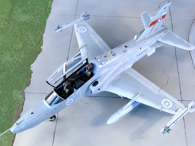
BAE SYSTEMS Hawk 127 LIF |
images by
Brett Green

HyperScale is proudly supported by Squadron.com
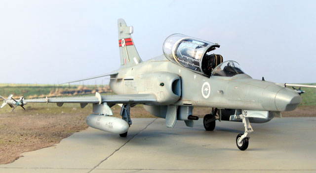
Here are images of the completed, soon-to-be-released, High Planes
1/48 BAE Hawk Mk127. For images of the kit parts during development,
click here to see my
Preview in the Reviews section of HyperScale.
|
High Planes 1/48 Scale BAE Hawk Mk. 127 LIF |
|
Advantages |
Excellent resin,
metal, plastic details.
Exceptional Decals |
|
Disadvantages |
Some scratch building
required.
Some flash on plastic parts. |
The kit was easy to build for a multi-media offering.
The plastic parts feature the usual heavy gate injection moulds, and
these have to be carefully removed from the sprue with a razor saw or
sharp knife. All the recess areas such as the cockpit, wheel wells,
engine exhaust, etc, have to be carefully cleaned up from moulding flask
and in some cases the area has to be sharpened up a bit. This is a
necessary process but not too difficult.
The next step before construction can begin is the cleanup of the mating
surfaces. I started by taping a sheet of 500 wet and dry paper to my
workbench, and softly sanded the mating surfaces until they were smooth.
The fuselage halves were then taped together and the cockpit, nose wheel
well, and engine exhaust were cleaned up and aligned. The engine exhaust
aperture was smoothed up using a large round file, as the opening is
circular. The nose wheel well area needs some plastic to be removed from
the bottom of the fuselage halves to achieve a square fit. The spine
area needs to be reduced to a flat surface across the fuselage; this was
done using a coarse flat file.
During the filing process it is paramount to keep trial fitting the
spine panel until a flush fit is achieved. The same needs to be done for
the lower wing area, until the lower wing fits snug into the recess.
Once these two areas are complete the fuselage halves can be reduced in
width.
Tape the cockpit halves in place and see how much slack is available,
this will give an indication as to the correct width on the nose area.
Taping the spine and lower wing into position will give the correct aft
fuselage dimensions. Reduce the fuselage halves on the wet and dry paper
until the correct width dimensions are achieved. Once this is done
correctly there will be no fit problems with the kit.
Before assembling the fuselage, the intakes should be cleaned up and dry
fitted.
Assemble the splitter plate to the intakes and then trial fit them to
the fuselage. A bit of cleanup work may be required on the fuselage
halves to achieve a good fit. Assemble the fuselage, lower wing and
intakes using tape and Blue Tack.
Trial fit the upper wing surfaces then clean up the inner wing to
fuselage mating surface. If this is done correctly then no filler will
be needed on the upper wing to fuselage join. Once this is done the
intakes can be glued into place using the rear edge and upper wings for
alignment. Fill the rear join before proceeding as there is no panel
line there, and it is much easier to fill and sand at this point.
Disassemble all the taped temporary construction and start assembly of
the cockpit as per the instructions. Trial fit the jet pipe adding a
support and end stop from scrap sprue. Assemble the fuselage as per the
instructions.
I deliberately left the nose wheel well out and then installed it
though the cockpit, this way achieving correct alignment and fit.
The spine was next. I drilled out the APU aperture and added and
exhaust duct. I then drilled out the inlet and exhaust ducts for the
heat exchangers, adding a mesh faceplate for the heat exchanger fronts,
and some ducting from plastic card for the exhaust ducts. The spine was
then glued in place. A minor error in the kit is evident at this point.
The rear cockpit bulkhead should have a ledge that is flush with the
canopy sills, but falls a few millimetres short. A strip of thick
plastic card was a quick solution in this case and hides the gap between
the cockpit tub and the spine bulkhead.
The wings were the next assembly stage. A piece of wheel well detail
needs to be removed from the lower wings. This is where Highplanes
changed design after the wing master was complete. They now include the
detail as a drop in box, which is a much better idea. The lower and
upper wing was assembled using tape, and fitted in place to the
fuselage. Only the lower wing was glued to the fuselage at this point.
When dry the upper wings were removed, final upper wing to fuselage
trimming carried out and then glued in place. There should be a very
large panel line on the lower forward wing to fuselage join, as there is
approx a 20mm gap filled with a recessed rubber seal, so don’t go crazy
with the filler.
The tail planes are the next fit. These require drilling and a piece
of rod to be attached for fitment. The correct angle for these and the
lower fins are supplied in the instructions.
The cockpit is fitted out at this point, and is very straightforward
with no fit problems. A small pipe needs to be removed from the MK10
ejection seats, as it is not fitted to the Hawk MK10s. The wing fences
and antenna bases are manufactured from plastic card using the templates
supplied on the instruction sheets and then fitted in place.
The final assembly work is the trimming of the beautiful Falcon vac-formed
canopy. This was then masked and painted black ready to receive a final
coat when the kit is painted.
Any remaining seams on the assembled airframe were finished with Mr
Surfacer 500 and sanded smooth. Touch up scribing was performed and then
the whole model was polished with steel wool.
Painting was then carried out with Xtra Color paints, and some subtle
panel highlighting was done with oils paints - Burnt Sienna for panel
lines, and Raw Umber for control surfaces, flaps, speed brake and Ram
Air Turbine doors.
The decals were then applied before a coat of semi gloss was sprayed
to seal the kit. They go on very well with no silvering and conform to
the surface detail. The decal for the canopy MDC is spot on. The MDC is
a shaped charge that is held in place with resin and this is replicated
perfectly. The decal film conveniently forms the resin. Many kit
manufacturers etch this into the canopy, and this is incorrect.
Assembly of the undercarriage presents no problem, with angles for
the main undercarriage doors being provided in the instructions. This
will ensure clearance for the gun pod if fitted at a later stage. The
antennas were then manufactured from plastic card and fitted. The canopy
bows were painted and then fitted. I manufactured some side rails from
plastic and fitted these to the canopy.
Highplanes may do a detail set in the future for the Hawk that will
include etched metal antennas and wing fences, resin dropped flaps,
Sidewinder missiles and outer wing pylons. These were not included in
the kit as they are considered optional and would increase the price.
High Planes has produced a very nice kit that requires no extra
detail sets other than some scratch building from plastic card.
The canopy is typical of Falcon - cleanly moulded and crystal clear.
The decals are exceptional and accurate.
The key to building the kit is trial fit, trim, trial fit, trial fit
again, and then glue. Spend the time in preparation and you will be
rewarded with an exact replica. This version supplied to me from High
Planes was the prototype moulding, and I have since received the
production run parts, which are even crisper.
Thanks to High Planes Models for the review parts.
The kit retails for around AUD$70.00 (approx. USD$41.00).
Available from:
High Planes Models
hiplanes@corryongcec.net.au
Snowy Mountains Models
http://www.users.bigpond.com/smmodels/
or email at
smmodels@bigpond.com
Model, Images and Text Copyright © 2003 by
Mick Evans
Page Created 03 February, 2003
Last Updated 17 March, 2004
Back to HyperScale
Main Page
|
 Home |
What's New |
Features |
Gallery |
Reviews |
Reference |
Forum |
Search
Home |
What's New |
Features |
Gallery |
Reviews |
Reference |
Forum |
Search