|
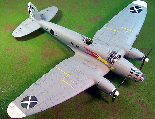
Heinkel He 111B "Pedro"
by Matt Swan
|
|
|
Heinkel He 111B |
Converting Monogram's 1/48 He
111 H4/5 to an early He 111B Pedro using the Cutting Edge resin conversion
kit.

Cutting Edge's 1/48 scale
He 11 Early Conversion sets
are available online from
Meteor Productions
Project start date 12/26/03
For this project I am using Monogram 1/48 scale kit #5509 of the
Heinkel He-111 H4/5
which you can take
a look at here and the Cutting Edge resin conversion kit #48446 to
back date the model to an early “B” Pedro version from the Spanish Civil
War. You can look at the Cutting Edge conversion kit and the decal package
I’ll be using by
following this link.
The Cutting Edge instructions are a little vague in places so it is
important to study all the parts carefully and think through your
conversion process. Right away, while examining the wing pieces I found a
problem - the left hand wing leading edge replacement piece has a nasty
warp to it. This issue was eventually addressed with hot water - we’ll
look at the correction technique a little later. The fuselage pieces on
the Monogram kit have a couple of sinkholes that will need to be filled
also just behind the cockpit. No other part problems were apparent at this
point in time.
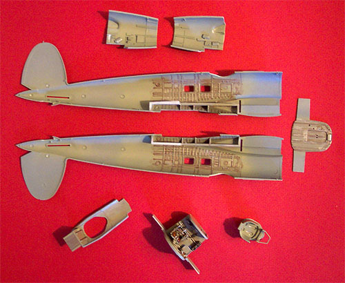
The larger resin pieces such as the nose sections and the clear resin
pieces are removed from their casting blocks with a cut-off wheel on my
Dremel while the smaller, more delicate pieces are removed with a razor
saw.
The nose of the Monogram fuselage needs to be removed and this is the
first area of decision. The CE instructions say to remove the nose at the
indicated panel lines – well they don’t really indicate anything so you
have to hold up the replacement piece and study the situation carefully.
If you cut right at the panel line you will create a gap between the
pieces that will need filling, rather you should cut about 1mm ahead of
the panel line even with the forward slot for the wing spar.
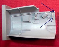
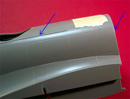 In
the picture to the right one blue arrow indicates the panel line to pay
attention to while the other indicates the slide track for the original
kit gunners dome which has to be removed. The slide tracks for the
original kit pilot access hatch have to be removed also. The kit nose is
sliced off with the Dremel and cleaned up with a sanding stick. I test fit
the forward bulkhead into the wing spar slots several times while cleaning
up the cut area so as to not remove too much plastic. All the while I am
doing this I am also considering the best approach to installing the four
pieces that will comprise the new nose. Should I attach them to the
fuselage sides then assemble the sides or should I assemble the sides then
attach the new nosepieces? In
the picture to the right one blue arrow indicates the panel line to pay
attention to while the other indicates the slide track for the original
kit gunners dome which has to be removed. The slide tracks for the
original kit pilot access hatch have to be removed also. The kit nose is
sliced off with the Dremel and cleaned up with a sanding stick. I test fit
the forward bulkhead into the wing spar slots several times while cleaning
up the cut area so as to not remove too much plastic. All the while I am
doing this I am also considering the best approach to installing the four
pieces that will comprise the new nose. Should I attach them to the
fuselage sides then assemble the sides or should I assemble the sides then
attach the new nosepieces?
Ultimately, I decided to assemble the fuselage as one step and assemble
the nose pieces into a left and right section then attach them to the kit.
While test fitting the new pieces I have found some interference
between the observer’s seat back and what looks to be a fire extinguisher
molded into the right hand sidewall. It’s still early into the project so
I will wait and see if this works itself out or not.
 Now
I examine the belly of the kit fuselage looking for the panel lines to cut
for the new gunners dustbin station. These panel lines are readily
apparent and just to make life a little easier I mark the area with a
magic marker before cutting. This area is also removed with the Dremel and
cleaned up with alternate treatments of a razor knife and a sanding stick.
Again, the replacement piece is test fit several times to each side of the
fuselage while the clean-up process happens. Now
I examine the belly of the kit fuselage looking for the panel lines to cut
for the new gunners dustbin station. These panel lines are readily
apparent and just to make life a little easier I mark the area with a
magic marker before cutting. This area is also removed with the Dremel and
cleaned up with alternate treatments of a razor knife and a sanding stick.
Again, the replacement piece is test fit several times to each side of the
fuselage while the clean-up process happens.
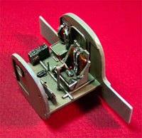
I’ve washed all the pieces in warm soapy water then let them air dry
before proceeding. Next I’ve removed the smaller cockpit pieces and
attached the various levers to the floor pan and dashboard prior to
painting. For most of you painting the interior of a Luftwaffe aircraft
means RLM66 black-gray but this color requirement did not happen until
1941 while the aircraft I am modeling was in service in 1939 so it’s
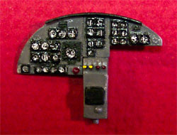
interior will be RLM 02 light gray. Control panels are done in black with
details picked out with white, red and yellow enamels. I’ve washed the
finished pieces with a sludge wash based around Higgins brown ink and
Grumbacher Ivory Black acrylic paste. The dash was done with RLM 66 and
the instrument clusters done in black then the faces whited out. Reheat
decals were placed over the instruments to finish it off.
 The
pilot and observer seats are finished and installed in the cockpit but the
dash is not glued in yet – it will be placed after the cockpit assembly is
attached to the fuselage and at least one side wall is in place to ensure
that the sun shield is in the correct position. The
pilot and observer seats are finished and installed in the cockpit but the
dash is not glued in yet – it will be placed after the cockpit assembly is
attached to the fuselage and at least one side wall is in place to ensure
that the sun shield is in the correct position.
The interior floor structure for the aft gunner’s position is test fit
then glued in place. I test fit the rear bulkhead at the same time so that
there will be no conflict between the pieces in later assembly.
The main pieces for the gunner’s dustbin are assembled and painted. I
have left the seat pan off until the other painting is complete. It took
me a few minutes but I finally figured out what the Cutting Edge
instructions were referring to as the “B Stand” and got the dorsal gunners
platform located and glued in place on the replacement ventral panel.
After the wash had dried I dry brushed the interior pieces with Model
Master Steel.
12/28/03
 I
have now taken care of various mundane construction processes now like
gluing together the stabilizer pieces and the main wheels. The tail wheel
assembly has been painted, assembled and installed into the fuselage also.
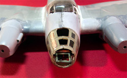
The Cutting Edge kit includes masks for not only the exterior windows but
for the interior windows in the nose and let me tell you – this was a
great idea. The clear nosepieces are of very different engineering then we
usually see in the model industry. All the details are molded on the
interior and the exterior is smooth. All the windows are recessed from the
interior. I polished the exterior with some very, very fine sand paper
then dipped both pieces in Future and let them cure overnight. Next I
placed all the interior masks and then airbrushed the interior RLM 02.
When I removed the masks the results were fantastic. I carefully added
some wash to the interior details of these parts then super-glued them to
the gray resin nosepieces to form my left and right side pieces. I
have now taken care of various mundane construction processes now like
gluing together the stabilizer pieces and the main wheels. The tail wheel
assembly has been painted, assembled and installed into the fuselage also.
The Cutting Edge kit includes masks for not only the exterior windows but
for the interior windows in the nose and let me tell you – this was a
great idea. The clear nosepieces are of very different engineering then we
usually see in the model industry. All the details are molded on the
interior and the exterior is smooth. All the windows are recessed from the
interior. I polished the exterior with some very, very fine sand paper
then dipped both pieces in Future and let them cure overnight. Next I
placed all the interior masks and then airbrushed the interior RLM 02.
When I removed the masks the results were fantastic. I carefully added
some wash to the interior details of these parts then super-glued them to
the gray resin nosepieces to form my left and right side pieces.
 Now
that the tail wheel and the rear floor structures have been installed I
can put the rear bulkhead in place, install the four rear fuselage windows
(with Black Magic masks in place) and close up the main fuselage. Tenex 7R
is my glue of choice when working with polystyrene and makes short work of
this step. After the glue had done it’s job the seam is sanded and the
bomb bay doors are glued in place. Next the resin cockpit assembly is
super-glued in place. At this point I test fit the new nose pieces and
once again I find interference between the observer seat and a fire
extinguisher. This piece will have to be removed from the sidewall and
relocated about 2mm forward of it’s original position. I also have some
slight problems with a small piece of framing at the same area that needs
to be notched to improve the fit. Now
that the tail wheel and the rear floor structures have been installed I
can put the rear bulkhead in place, install the four rear fuselage windows
(with Black Magic masks in place) and close up the main fuselage. Tenex 7R
is my glue of choice when working with polystyrene and makes short work of
this step. After the glue had done it’s job the seam is sanded and the
bomb bay doors are glued in place. Next the resin cockpit assembly is
super-glued in place. At this point I test fit the new nose pieces and
once again I find interference between the observer seat and a fire
extinguisher. This piece will have to be removed from the sidewall and
relocated about 2mm forward of it’s original position. I also have some
slight problems with a small piece of framing at the same area that needs
to be notched to improve the fit.
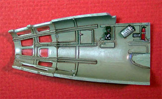
In the first picture below you see the original nose piece with blue
arrows indicating the two areas of interference. In the second picture is
the nearly finished nosepiece with the fire extinguisher relocated and the
framing notched out. There are still a few minor detail pieces to be added
to the interior and the upper two windows will be installed after the nose
has been completely assembled.
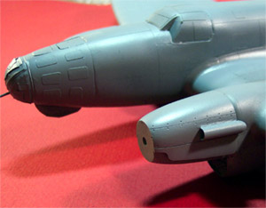
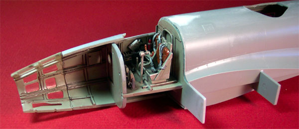
In the next picture we can see the main fuselage assembly with the
right side nose piece in place, it is not glued but simply held in place
by the structure itself at this point. Take note of the fuselage top, you
can see that all the slide rails have been removed, the panel lines have
been rescribed across the glue seam and where the Monogram kit had some
sinkholes – they have been puttied and sanded. So far this is the only
place that has needed any putty, I don’t think I will be so lucky as the
conversion progresses.
12/31/03
As I move into the wing modification this conversion kit begins to show
it’s teeth. Once again vague instructions from CE are hampering the work.
The instructions state to cut off the wing leading edge on the indicated
panel lines. From looking at the parts this seems to indicate a double
line that runs the length of the top of the wing. I figured out that I
must cut the leading edge off at the inner of the two panel lines. Okay,
no problem doing that. Now looking at the bottom panel of the wing I see
another single panel line that runs in the same location, or at least it
looked like the same location – not.
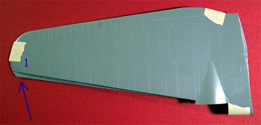
In the photo above we can see what happens after following these two
panel lines. Fortunately it is a matter of not having cut off enough
rather than having cut off too much. At arrow #1 there is a good quarter
inch of overlap that needs correcting. On the lower panel at the engine
cowling the panel line is at the correct starting point, it just ends at
the wrong point. I taped the wing halves together and placed a small cut
on the bottom half wing tip where it meets the top half wing tip then laid
a piece of masking tape from the beginning point at the engine nacelle to
the cut mark and scribed a new line to mark the additional area to be cut
off.
That solved the first problem.
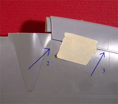
When test fitting the resin pieces I found that things were not quite
meeting up. To fix this problem the top wing leading edge must be cut into
the engine nacelle just a little bit until you reach the panel line
indicated by arrow #2. See arrow #3. The cut line at that point forms the
second of the double panel line where the original cut was made, compare
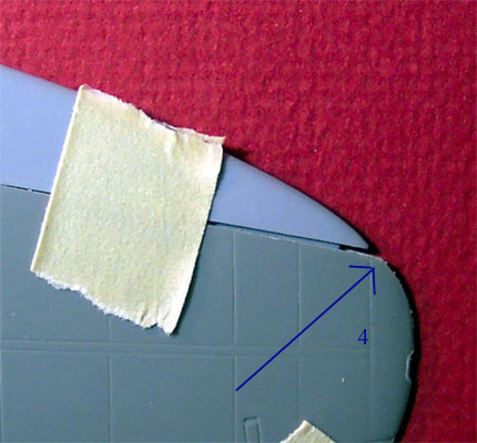
this to the uncut wing from your kit. Also, once the cut has been made you
must sand some plastic off the inside of the wing along the cut line, both
top and bottom, or the plastic wing will sit proud of the resin leading
edge. The replacement leading edge does not extend all the way to the end
of the original wing and you must reshape the wing tip (see arrow #4 in
the picture above). You must also thin the wing material at the tip by
sanding the inner surface prior to assembly.
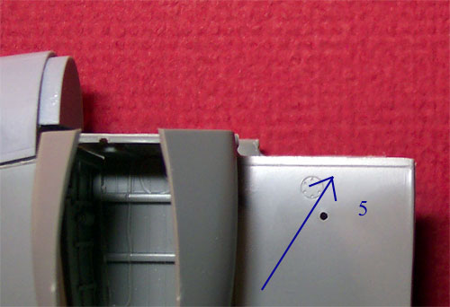 That
pretty much handles the problems centered around the main leading edge.
The small section between the engine nacelle and the wing root has similar
concerns. You can cut the top wing panel at the obvious panel line but the
lower wing half has no line that can be followed. If you cut the line that
looks right on the lower panel you will be in big trouble as you will have
cut off TOO MUCH and that is difficult to fix. See arrow #5 - that's
exactly 1mm from the panel line to the cut line. The whole wing thing is
looking good now (after 3 and a half hours of work) but I will not glue
any of these parts together until I have test fit all this to the fuselage
to ensure that everything meets up correctly. That forward wing spar is
going to be a problem also, I can see that right now. That
pretty much handles the problems centered around the main leading edge.
The small section between the engine nacelle and the wing root has similar
concerns. You can cut the top wing panel at the obvious panel line but the
lower wing half has no line that can be followed. If you cut the line that
looks right on the lower panel you will be in big trouble as you will have
cut off TOO MUCH and that is difficult to fix. See arrow #5 - that's
exactly 1mm from the panel line to the cut line. The whole wing thing is
looking good now (after 3 and a half hours of work) but I will not glue
any of these parts together until I have test fit all this to the fuselage
to ensure that everything meets up correctly. That forward wing spar is
going to be a problem also, I can see that right now.
As I had mentioned in the beginning of this article I had a warped
leading edge piece. Now this piece was labeled as the left hand piece but
from everything I could see it was actually the right hand piece. It was
not until I was actually working on the wing modification that it became
apparent that Monogram had labeled the wings from the modeler’s point of
view and not the pilot's as they should have. It seems that Cutting Edge
was trying to conform to the kit labeling when they labeled their parts.
Just one more item of confusion. Anyway, back to the warped piece. I
heated up a bowl of water to 180 degrees Fahrenheit and let the offending
piece soak in it for about five minutes to absorb the heat. I laid it on a
flat surface and pressed it back into shape and held it while it cooled
and the warp was removed. Later on as I worked on the wing I found more
warpage in the resin engine-to-wing piece that will be corrected in the
same manner.
1/2/04
There is a lot of stuff happening with the wing and the directions
really suck on the coverage of this area so in an effort to help out
future modelers attempting this conversion I need to spend just a little
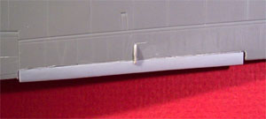
more time on this subject. This next picture shows the tape demarcation
for the new cut line on the bottom wing half. Once the tape is laid out I
place a flexible steel ruler over the tape then scribe the line with my
Xacto knife.
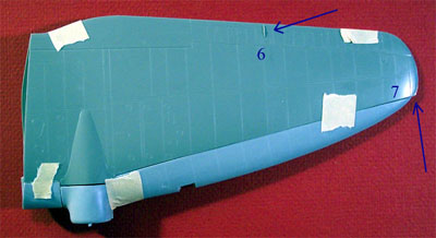
After a lot of test fitting and thinking about it I have finally glued
the main wing panels together. The gear doors/bay walls have been glued in
place but no resin parts have been glued in place yet. In the following
pictures arrow #6 indicates the trim tab actuator that has to be removed
temporarily. I carefully slice this off the wing and set it aside until
the new extended trim tab has been installed. There is another actuator
underneath the wing but if you are careful about the removal of the molded
in trim tab you should not have to mess with it. Arrow #7 illustrates the
unmodified wing tip. In this shot we are looking at the left hand wing,
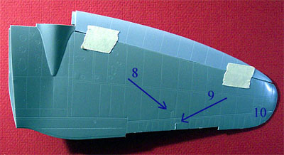
which all the instructions identify as the right wing. In the next picture
the trim tab has been removed. Arrow #8 indicates one of several engraved
hinges that will have to be filled and sanded. Arrow #9 indicates the mark
from removing the upper trim tab actuator – don’t sand this off as you
will need it to help locate the actuator when you reinstall it. Area #10
shows the reshaped wing tip both front and back, yes the backside has been
sanded to create a more elliptical shape.
Click the thumbnails below
to view larger images:
 And
finally, here you can see the new, extended trim tab in place with the
actuator reinstalled. The kit instructions at this point tell you to
install the rhomboidal aileron baffles in the indicated positions under
the wing. And
finally, here you can see the new, extended trim tab in place with the
actuator reinstalled. The kit instructions at this point tell you to
install the rhomboidal aileron baffles in the indicated positions under
the wing.
Guess what? There are no indicated positions! There are no pictures of
the underside of the wing whatsoever!
For this I needed to turn to the experts on HyperScale and those most
helpful people produced information that indicates this baffle should be
mounted just forward of the aileron and about three quarters of an inch
from the outside edge of the landing flap – thanks Peppy.
1/4/04
After two more evenings of modeling time devoted to the wings, many dry
fit sessions and a review on how to swear like a sailor the wings have
been assembled – mostly.
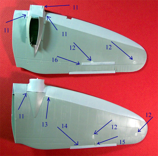
Here we can take a quick review of all the various modifications and
some of the problems encountered. Arrows numbered 11 illustrate the many
areas where I had to use repeat applications of super-glue and accelerator
to fill gaps. Arrows numbered 12 indicate the engraved hinges that have
been filled with Squadron White Putty. On the lower side of the wing the
hinge material had to be cut out of the hinge line to make it a continuous
engraved line. Arrow number 13 indicates one of about four different areas
where very small gaps had formed along the new leading edge. These were
filled by putting some putty on a cotton swab with some acetone based
fingernail polish remover and then rubbing it into the gap. Arrow 14 is
the new extended trim tab and 15 is the actuator. Arrow 16 is the
rhomboidal baffle installed forward of the aileron on the lower side of
each wing.
All the super-glue fills were shaved with a Xacto leaf blade then
sanded smooth. After all puttying, filling and sanding had been finished I
went over all the panel lines with the tip of my #11 Xacto blade and
cleaned the debris out of them. Both wings were then wiped down with a
Micro Sheen tack cloth. I still have to install the engine nacelles and
radiators but that will wait until after the gear bays have been painted.
The CE instructions talked about cutting or grinding a slot into the
back side of the leading edge pieces to accept the forward wing spar.
Screw that! I’ve had enough of these wings already and simply chopped the
forward wing spar off even with the fuselage wall and will use plenty of
super-glue to attach the wings. It has been a lot of work and a lot of
headache but I think the wings are looking pretty nice at this point. They
also dry fit well to the fuselage with that wing spar removed.
1/6/04
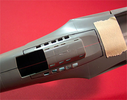
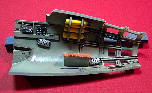 I’m
getting ready to attach the nose pieces and wanted to include a picture of
the left side equipment here because it will be about impossible to see
once everything is in place. Getting these nosepieces to meet up with the
fuselage and with each other is no easy task. I have a good-sized gap
along the bottom and had to stress the top to get it to meet. Once again
I’m filling with superglue and trimming seams. I’m
getting ready to attach the nose pieces and wanted to include a picture of
the left side equipment here because it will be about impossible to see
once everything is in place. Getting these nosepieces to meet up with the
fuselage and with each other is no easy task. I have a good-sized gap
along the bottom and had to stress the top to get it to meet. Once again
I’m filling with superglue and trimming seams.
The final piece of glazing to go onto the nose is salvaged from the kit
nosepiece. I have cut it off and sanded the edges smooth and then test fit
it. Guess what – it fit perfectly! I can’t glue it in place yet as there
are still a few detail pieces to go into the nose but it’s nice to know
that I will not have to fight with this piece.
The next item for some attention is the engine nacelle. I want to be
able to have the propellers mobile. To achieve this I locate the center of
the cowling face then drill it out to a size equal to the original kit
prop shaft pin. After figuring this all out and doing it I discovered that
the interior of the engine nacelle is already marked with a small stub of
the correct size in the correct position to assist the modeler. And I felt
so good about my centering job too. All right then, now both nacelles are
mounted to the wings and the nacelle extensions are place underneath. All
the gaps are filled with superglue and trimmed up.
 Now
that the engine nacelles and nose seams have been finished off I’m ready
to attach the wings. Now
that the engine nacelles and nose seams have been finished off I’m ready
to attach the wings.
I coated the inner wing joint areas that are resin with superglue and
let that tack the wing in place then applied Tenex 7R along the rest of
the seam. The resulting joint was finished by fencing the seam with tape
then applying Squadron White putty to it and then smoothing it out with
fingernail polish remover.
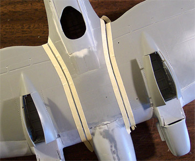
This photo to the left shows the underside just before the putty is
applied. Notice that the engine radiators are not installed yet, I still
haven't gotten around to painting the gear bays yet - soon.
While that dried down I attached the elevators and did some detail
painting on the remaining interior pieces like the bombardier’s couch.
1/12/04
The Bombardier’s couch went right in and there were a few odd little
control boxes that I placed and the exterior bomb-sight mechanism. I
painted the kit machine guns and set them aside to dry. The instrument
panel gets installed at this point also - a very fiddly process and took
about five minutes to get placed where I wanted it to be but I am glad I
waited until now to do it.
I used the Cutting Edge masks for the nose windows then turned my
attention to the main cockpit windshield. This is kind of an odd piece,
cast of clear resin but very flexible once cut off the casting block. It
took several test fittings and sanding sessions to get a good fit but
finally it was fitted, Futured and glued in place. After the seams were
touched up I applied the CE masks to this piece also.
 Now
I started work on the remaining clear resin piece on the nose. This part
is for the two top center panels and is provided as a single, separate
piece to be installed just before the nose dome goes on. The piece in my
kit has several micro-bubbles in it and feels slightly sticky as if the
resin did not set completely. I Futured the part before working on it to
try to prevent fingerprints from being embedded into the material or
having dust particles embedded into it while handling. On the first test
fit it is apparent that it will not fit as designed. After a few trimming
sessions with a diamond needle file I decide the best way to approach this
will be to separate the two panels, remove the cast lip around the edges
and install them as single panels. This approach does indeed make life
easier. One more test fit then they are masked with masking tape and
installed. Odd thing, CE gives us this huge masking set but does not
include masks for these two panels. Now
I started work on the remaining clear resin piece on the nose. This part
is for the two top center panels and is provided as a single, separate
piece to be installed just before the nose dome goes on. The piece in my
kit has several micro-bubbles in it and feels slightly sticky as if the
resin did not set completely. I Futured the part before working on it to
try to prevent fingerprints from being embedded into the material or
having dust particles embedded into it while handling. On the first test
fit it is apparent that it will not fit as designed. After a few trimming
sessions with a diamond needle file I decide the best way to approach this
will be to separate the two panels, remove the cast lip around the edges
and install them as single panels. This approach does indeed make life
easier. One more test fit then they are masked with masking tape and
installed. Odd thing, CE gives us this huge masking set but does not
include masks for these two panels.
On to the final piece, the nose dome. Remember, this is cut from the
Monogram kit nose cone. The gun is installed and the dome it test fit –
looks good. Now, to mask first, the CE mask for this piece is very
ungainly and I decide to mask the dome with strips of masking tape
instead. This works out fine for me, and the dome is attached with
Testor's Clear Parts Cement.
Finally this bird makes it to the paint room. The landing gear bays are
shot with RLM 02 and so are the interiors of the engine radiators. The
radiator elements are painted with Gunze-Sangyo Burnt Iron and washed. The
interiors of the gear bays are washed then dry brushed with Model Master
Steel. Now the radiators are installed. From here I start stuffing tissue
paper into various openings such as the top gun position and the ventral
gun position. Both front and backsides of the radiators are stuffed and
the gear bays are stuffed. The insides of the gear doors are covered with
some masking tape.
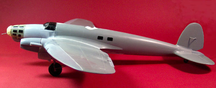
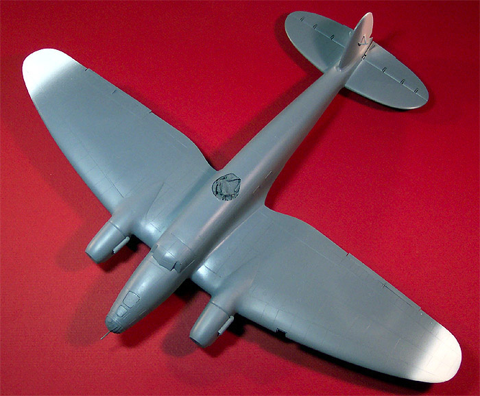
Doesn't look like your standard 111 anymore, does it?
The picture above was taken with the landing gear held in place by the
gear doors. They were then removed for the painting process. I start this
process by prepainting the clear parts with Gunze-Sangyo RLM 02 then
shifting to Model Master enamel primer gray cut 25% with lacquer thinner
and shooting the entire aircraft. I have traced all the engraved panel
lines with the tip of my razor knife to clean them out, wiped everything
down with my micro sheen tack cloth and blown the model off with
compressed air before painting and now whenever I handle it I am wearing
cotton inspection gloves so I cannot leave any fingerprints or finger oils
on the surface.
In between painting sessions I will take care of some of the smaller
subassemblies like the dorsal and ventral gun positions, the propellers
and the exhaust shrouds.
1/14/04
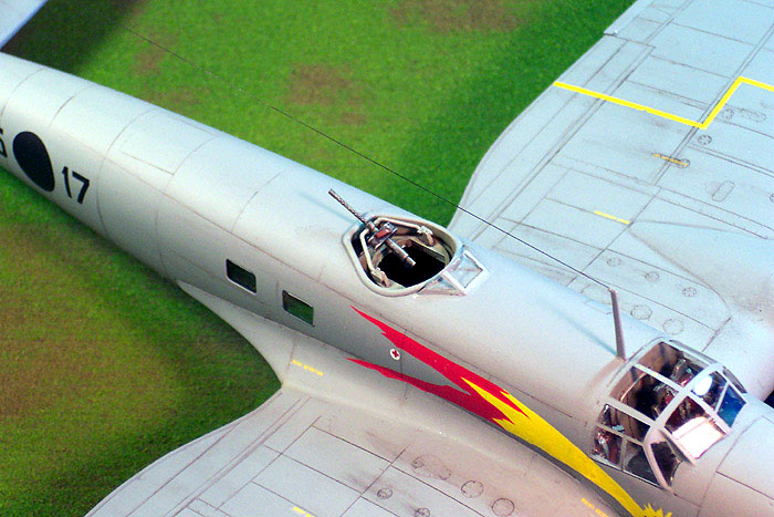
Prior to closing up the fuselage I had test fit the ventral or
‘dustbin’ gun and had needed to sand just a little off each side of the
transit block to allow it to fit snugly into the track on the dorsal
gunners ‘B Stand’. This is important because once complete the dustbin
will not be glued in place but simply rest in position so as to be
adjustable. It will not fall out because the upper edges of the gun
fixture need to be compressed to allow it to slide into the fuselage. As
you can see in the picture, the gun station has been completed. That is
the Monogram gun and everything else is CE resin. The seat itself did
present some difficulty needing to have both back corners trimmed to fit.
As far as paint goes we have an overall RLM 02 with a sludge wash and a
dry brush of steel. The belts were done in a very light gray with silver
hardware and the gun was done with Gunze-Sangyo burnt iron. The bottom of
the fixture will be done with RLM 77 to match the exterior of the
aircraft.
The next subassembly to look at is the propellers. If you will recall
previously I had drilled out the engine nacelles to accept the Monogram
kit propeller shaft. The spinner covers and backing plates are being
replaced with Cutting Edge pieces and we are using the Monogram kit
propellers and propeller shafts. One spinner had a concealed air bubble in
it that became exposed when I cut the casting block off of it and that had
to be filled with super-glue. The backing plates had to have the central
hole enlarged with a round diamond file until the propeller shaft would
slide easily through it. When test fitting the propeller into the spinner
cover I found it to be a very tight fit, in fact on further examination it
would not set far enough into the spinner cover to allow the back plate to
rest in place. I deepened each slot for the propeller blades with an oval
diamond file (arrow #17) and shaved the inside edges at an angle to help
the blade cuff to clear. Another test fit and the back plate is still not
quite where I want it. Now I look at the back plate and file the rounded
area that the back of the blade seats into. This will accomplish two
things; it will help the back plate to seat and it will give me just a
little more length on the propeller shaft to insert into the engine
nacelle. As they are pictured here all the pieces are simply resting in
place so the fit is now pretty good.
How’s the painting been going you ask? Pretty darn good. I’ve got the
first coat of primer on the model and dried down. There were a few seam
areas that needed touching up and a couple of small spots that needed a
little more fill but that’s why we prime – to find these things now rather
than later. I had also been giving the exhaust shrouds some thought while
the first coat of primer was drying. I didn’t want to be messing around
with Superglueing these on after my paint job is complete. The solution I
came up with was to glue the shroud in place with the exhaust stacks held
in place, hit it with some accelerator then remove the stacks. This seemed
to work pretty well. After these items had been addressed I laid some more
primer on it and then applied some Testor's flat enamel white cut with
lacquer thinner to the tail and the wing tips.
Click the thumbnails below
to view larger images:
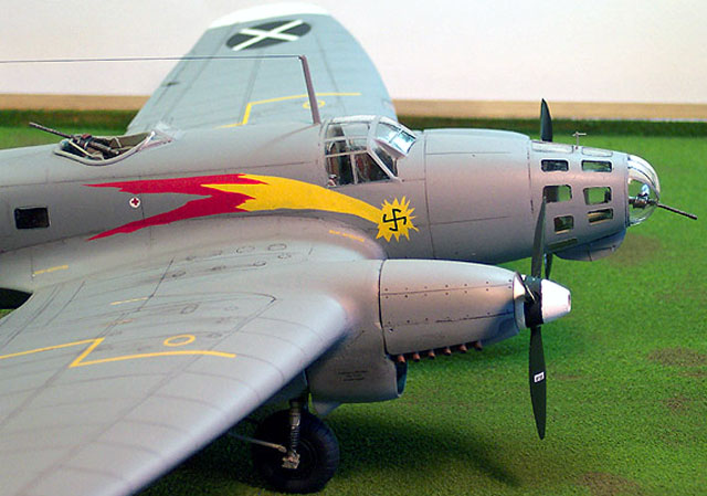
In the third picture you can see the exhaust shroud in place on the
engine nacelle. I would also like to direct your attention to the top two
windowpanes on the nose. Those are the two that were so difficult to place
during assembly. Another item I want to point out is that with the nose
dome being masked with tape rather than the Cutting Edge mask it makes it
look like it sits proud of the rest of the fuselage, it does not. It’s
just an optical illusion.
Tonight’s session will definitely make a difference in the overall look
of the model. I shall mask the wingtips and rudder tonight and mix my
paint (RLM 77). Once that is on I can install the landing gear and put
some Future on the day after that. The anticipation is almost more than I
can bear.
1/16/04
 It has been two days of serious modeling fun. It has been two days of serious modeling fun.
I began by masking the white wingtips and rudder off with strips of
masking tape and attaching the upper and lower aerial masts. I had
intended to paint the aircraft RLM 77 but this is a very difficult color
to find premixed. I did find an enamel from Testors but it had a very blue
look to it. Ultimately I had to go back to my RLM paint chips and mix to
match. I started with Polly Scale RLM 76 and added Polly Scale Uniform
Gray to it in small quantities until I had a dry paint spot that matched
my paint chip. I made sure that I mixed up about two ounces of paint so
that I would have plenty to finish the job – heaven forbid that I run out
of a custom mixed paint 95% of the way through this. Off to the paint
room!
After a quick dusting with compressed air she got three light coats of
RLM 77. I removed the masks from the white areas within the hour, did some
little paint touch-ups with a brush and installed the completed dorsal gun
position. All the tissue packing was removed, the landing gear were
installed and I set her aside to dry for the night. The next day during my
lunch break (yeah, I have a regular job) I coated it with Future floor
polish. After a five-hour drying period I began to apply the decals. I am
using a combination of the basic stencils that came with the Monogram kit
and the Cutting Edge ’Pedro’s in Spain’ sheet for the Condor Legion of the
Spanish Civil War. The Monogram decals have some nasty film on the decal
paper that lifts off in chunks when the decal is wet. I found that I had
to rub the decal with my fingertip in water immediately to flush off this
film then let it soak for a few for the decal to lift from the paper. The
CE decals behaved very nicely and gave me no trouble at all. All the
decals responded very nicely to Micro-Sol setting solution. When applying
the decals to the rudder and fuselage I propped the tail wheel up to level
the plane and make it a little easier to keep all the decals orientated
properly. To keep the wing tip national emblems in the proper orientation
I measured from the white edge to the tips of the white cross giving each
one a clearance of ten millimeters. Overall I spent about three hours
placing decals and applying setting solutions.
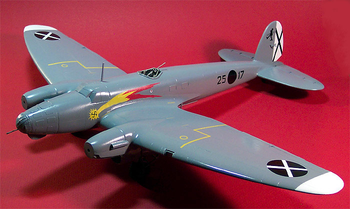
She’s turning into one hot Spanish babe of German ancestry. Once the
decals have had a day to dry thoroughly I will seal everything with Future
and begin the weathering process.
1/19/04
Another coat of Future has dried down now and the weathering begins.
I’ve mixed my standard sludge wash of Grumbacher Ivory Black, Higgins
brown ink, liquid dish soap, Liquitex flow aid and lots of water. This has
been applied to all the panel lines and then wiped with a damp paper towel
compress. The fuel caps and service ports had another drop of wash placed
on them and allowed to dry then I dampened my fingertip, placed it firmly
on the dried spot and gave it a quick wipe to the rear to create the
streaking effect. The aerial is made from invisible thread drawn across a
black permanent marker and super-glued in place.
The exhaust stacks were airbrushed with Polly Scale rust and the open
ends were touched with Tamiya flat black then they were installed. They
slide nicely into place with no problems at all. Exhaust staining was a
two-part process; first a base mark was laid down with my airbrush using
Tamiya X-19 smoke and then I brushed ground brown, gray and black chalks
over it. One more trip to the paint room for a coat of Polly Scale clear
flat, you have to take care not to blow flat paint in through the upper or
lower gun stations as it will fog the insides of the four fuselage
windows.
While that was drying I airbrushed the propellers RLM 70 black green.
The hubs were done with Model Master Steel. The spinner covers got a good
coat of Testors flat white then were masked for the black strip to be
applied. The interiors of the spinners were done with RLM 02. By this time
the clear flat was dry to the touch and all the window masks were removed.
There was a little masking glue left behind in a few spots which was
removed with a toothpick that had one end sliced into a wedge and dipped
into Goo-Gone. It is almost done, two items left; the dorsal gunner’s
windscreen and the landing light lens. The gunner’s windscreen suffered
from the same sticky effect that the top nose glazing had. It had to be
handled carefully to not leave fingerprints embedded into the material.
The Monogram kit lens cover apparently is intended to be placed into the
wing fitting but it is way too small. I cut down a plastic sequin for a
landing light and made a new lens cover from some clear plastic card. Once
cut to the proper dimensions I folded it across a paintbrush handle then
held it over a light bulb to lock in the new shape – worked like a charm.
The VDM prop logo decals were placed on the propeller blades and they
were given a good brush coat of Future. Once the Future had dried the
propellers were assembled and snapped into place.
The ventral gun position is just snapped into place, for
photographs on the ground I have removed it so it looks like it’s in the
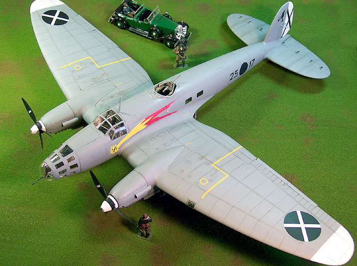
retracted position. For scene accessories I have the crew from a Pro
Modelers Me-410, a German pilot and ground crew member from Verlinden and
an old Renwal 1931 Cadillac Sport Phaeton – I think it could pass for a
German Staff car.
Click the thumbnails below
to view larger images:
So in summary here are some key points and observations:
-
The Cutting Edge directions leave something
to be desired – not very comprehensive.
-
Care must be taken when cutting up the
wing, new line must be scribed for lower panel cut line.
-
Cut kit nose off slightly forward of
indicated panel line.
-
Fire bottle at observer’s position must be
relocated.
-
Chop off those resin forward spars and glue
the wings directly to the fuselage.
-
Gray resin nosepieces don’t fit well.
-
Some clear resin pieces suffered from
incomplete setting process, possible from poor material mixing.
Otherwise the resin pieces were of good quality and good workmanship.
-
Lens for landing light must be fabricated
from stock material.
-
Some parts displayed warpage and others
required quite a bit of trimming to fit properly.
-
The Monogram decals have a film that must
be rubbed off before the decals have loosened from the paper.
-
The Cutting Edge decals behaved great with
no problems at all.
-
While the clear resin piece for the main
canopy is very clear and gives a good impression, the nose clear resin
pieces create a lot of optical distortion.
Overall this makes into a very nice kit, if the instructions were
better it would have been a much more pleasant build. While it may seem
like I cranked this out in record time, during the first week I was off
work for the holidays and devoted about 45 hours to the kit. Over the next
three weeks I put another 60 to 70 hours into the modeling process, which
means this is an 100 to 110 hour conversion project. I love the look of
the model but doubt that I would attempt another one of these in the near
future.
Model, Images and Text Copyright © 2004
by Matt Swan
Page Created 21 January, 2004
Last Updated
17 March, 2004
Back to
HyperScale Main Page |
 Home |
What's New |
Features |
Gallery |
Reviews |
Reference |
Forum |
Search
Home |
What's New |
Features |
Gallery |
Reviews |
Reference |
Forum |
Search