|
Hughes H-1B
by
Jim Kiker
|
|
|
Hughes H-1B |

HyperScale is proudly supported by
Squadron.com
Author’s note: An abbreviated version of
this article has previously appeared in “Bent Throttles,” the newsletter
of the Racing and Record Aircraft Special Interest Group (SIG). This
article appears with the kind permission of the SIG leader and editor of
the newsletter, Anders Bruun. For more information, check out our SIG on
the Internet at
http://members.chello.se/ipmsairrace/ .
I am old enough to remember Howard Hughes when he was still alive, living
the end of his life as a recluse, and being just a bit mad. Long before
that, Hughes had built up the machine tool company he had inherited while
still a young man, and had made his fortune. He later parlayed it into an
international corporation, not to mention doing a lot of clandestine work
for the U.S. Government.
In 1934, Hughes decided to build himself an airplane that would set
records and be on the cutting edge of technology, and the Hughes H-1B was
all that and more. Designed primarily by Dick Palmer and built in secret,
the aircraft was completed in 1935, and featured the first all-metal
monocoque fuselage with flush, butt-joined skin panels (which quickly
became standard on commercial and military aircraft). The original version
of the plane featured short-span wooden wings, although the aircraft was
later rebuilt with a longer-span wing (also of wood construction, going
from 24’ to 32’). Since the aircraft was conceived to be a record-breaking
vehicle from the very beginning, no expense was spared to create the
slickest, fastest possible airframe.
The original short-winged version set a new speed record of 352.322 mph
in 1935. In 1937, Hughes flew the long wingspan version of the plane to a
new transcontinental speed record of 332 mph, making use of an on-board
oxygen system and a true 3-axis autopilot system. Once Howard had set
records with the H-1B, he lost interest in it and placed it in storage.
The aircraft is now housed in the National Air and Space Museum in
Washington, DC.
In the 1990’s, another machine tool company owner, Jim Wright, decided
to build a replica of the Hughes aircraft. Years later he finished the
project, and in 2002, the Hughes Replica took to the air. Jim took the
airplane to the national air races in Reno last year, and set a new speed
record for the aircraft’s weight class. With much sadness I must also
report that Mr. Wright lost his life in a recent crash while flying home
from an air show. His is a great loss to the aviation community.
The only kit of the Hughes H-1B that I know of in 1/48th scale is a
resin kit produced by NOIX models of Japan. Although both the short span
and long span versions were produced in kit form, the long-winged version
is currently out of production, and even the short spanned one is not easy
to find. The good news is that it’s a nice kit for a limited-run resin
piece, with fair surface detail, cast metal landing gear and prop, two
vacuformed canopies, and a really nice standing figure that is
unmistakably Howard Hughes.
I like to add a certain level of detail to my models, and especially so
in this case. The kit has very nice outlines and a fair degree of surface
detail built into it, but it certainly profits from some additional
details here and there, especially in the cockpit, the cowling support
struts that are visible at the front of the plane, and the landing gear.
 The
cockpit was similar to other racing planes of the day, although Howard had
the various components scattered around to suit his own taste. The
instrument panel is more complicated because of the autopilot
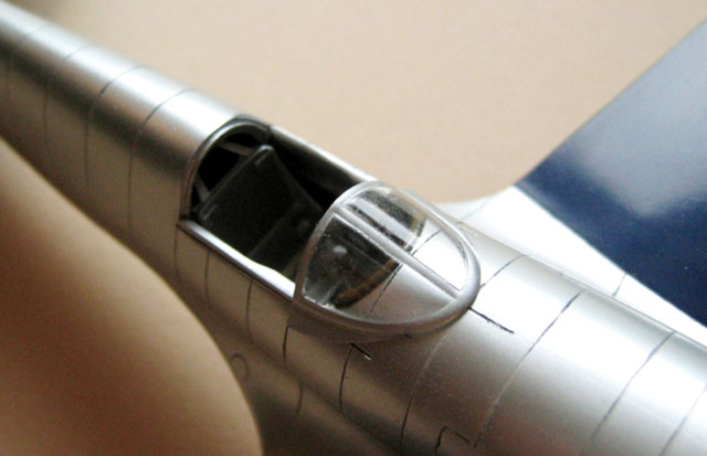
installation. Of special note is that the windscreen could be pushed
forward, and the canopy (split along the top) could be slid down into the
fuselage, somewhat like car door windows. This allowed Howard to raise the
seat forward and up in order to see over the nose better for takeoff and
landing. The
cockpit was similar to other racing planes of the day, although Howard had
the various components scattered around to suit his own taste. The
instrument panel is more complicated because of the autopilot
installation. Of special note is that the windscreen could be pushed
forward, and the canopy (split along the top) could be slid down into the
fuselage, somewhat like car door windows. This allowed Howard to raise the
seat forward and up in order to see over the nose better for takeoff and
landing.
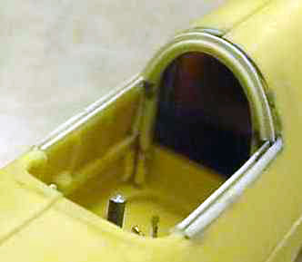
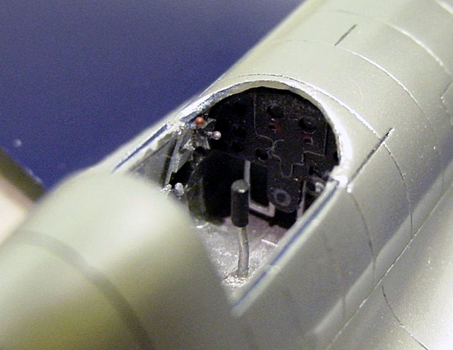
I hollowed out the kit fuselage behind the pilot’s seat since this area is
open on the real aircraft. The real cockpit was confusing since Howard had
the various components scattered around to suit his own taste; I improved
the side rails of the cockpit with strip plastic, then added an open
bulkhead at the rear of the cockpit, the throttle quadrant, a few knobs,
and later, a new seat.
The instrument panel is useable, with either some instrument decals or
some markings added to the blank instrument faces. Most of this will not
be very visible. The cockpit interior has a comparatively rough surface
and should be primed before painting. Towards the end of the build, I also
added a piece of wire insulation around the front edge of the cockpit and
painted it brown to simulate the padded coaming.
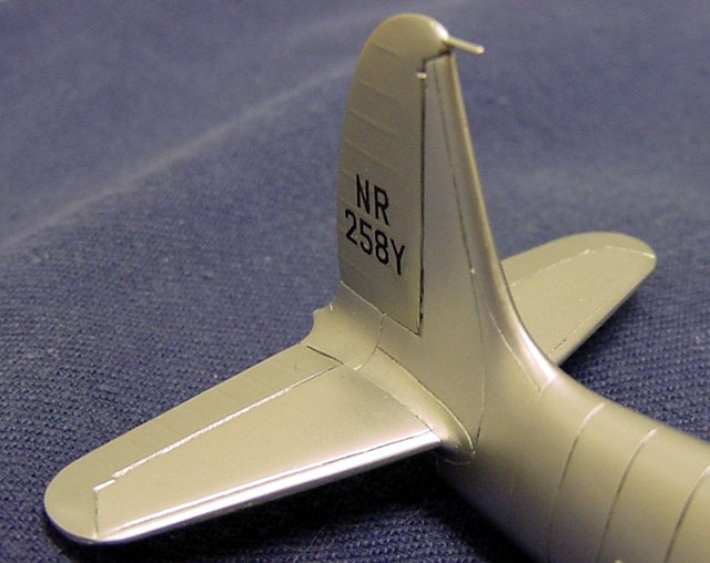
The fuselage itself is in two main parts, with the vertical fin and rudder
supplied as a separate piece. These pieces are finely scribed, although I
could not make all of the vertical panel lines line up. In retrospect, I
should have made sure the panel lines on the forward top of the fuselage
lined up better, then reworked the ones on the rear of the fuselage! The
wing and tail planes are each comprised of a single piece, and have rather
heavy, wide but shallow engraving for their panel lines. I have refined
all the panel lines, both during and after assembly. Given my skill level-
this is the first all-resin kit I‘ve built- getting the panel lines right
has been a case of “two steps forward, one step back.” I found that using
a pointed scriber tends to pull resin chunks out rather than making a
smooth line, so I switched to some very fine razor saws to improve the
panel lines. They work great on the straight lines, rather less so around
gentle curves, and there are several places where they failed me
altogether. I used tiny dots of superglue to fix my mistakes, added with a
fine piece of wire. If you use this technique, be sure to sand out the CA
immediately; waiting even a half hour will allow it to harden so much that
you will sand the resin away before smoothing down the CA itself. I did it
this way so that I would not have to worry about putty coming out of a
very fine cut line, and so I could saw/scribe over my mistakes. Using the
very fine drawings by Paul Matt, I made my own templates to re-scribe the
curving line of the fairings at the front and rear edges of the wing.
Rescribing that entire joint line around the wing was difficult, and while
my work isn’t perfect, it turned out pretty well.
On the original airframe, the recesses for the wheels themselves are a box
shape made of metal, and the outer surface covering is also in metal with
circular cutouts for the wheels. On the kit, this area is represented with
two cylindrical-shaped depressions. Given the one-piece molding, it would
be very difficult indeed to recreate the larger boxed-in recesses.
I used a drum-shaped sander in my Dremel tool to deepen these recesses
until the resin started getting thin enough to see light through. I added
a coat of CA glue on the outer surfaces of the wells where they are hidden
in the fuselage, to give the thinned resin some extra strength. When the
wells were painted, I added a final light coat of dark aluminum into the
center of each recess to make them look even deeper. The effect resembles
a deep cylinder-shaped recess hammered out of aluminum sheet, and I can
live with that!
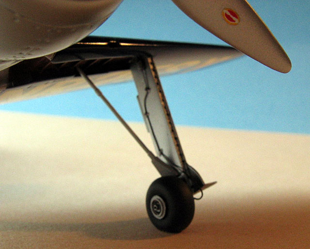
The landing gear is cast in white metal. The main struts are flattened box
shapes which are beefy enough to support the weight of the model, but the
axles for the wheels seemed a little weak to me. I cut them off, drilled
holes into the bottom of the gear struts/boxes, and replaced the axles
with steel wire and tubing to make them larger and more to scale.
I also marked and drilled the holes visible along the front edge of the
landing gear strut boxes. I used epoxy cement and glued the inner gear
door pieces to the bottom of the main struts. They were hinged and stuck
out to the side when the gear was down. When the gear was retracted, these
doors closed and covered the entire wheel in each bay. I primed and sanded
the struts, especially the outer surfaces, since they were rather uneven.
I added brake lines to complete the landing gear.
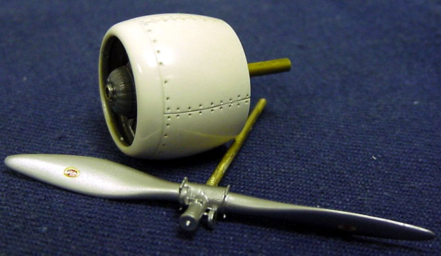
The engine and cowling are nicely cast, with a separate front ring and
a very nice engine front to be trapped between the two cowling pieces. I
drilled out the engine and forward fuselage to take a 3/32” brass tube to
accommodate a 1/16” brass shaft for the propeller. I also found that when
I dry fitted the engine and cowling pieces, the contours around the front
edge of the cowling were in error and did not match up well with each
other. I deepened all the panel lines and fasteners before gluing, and
after the pieces were glued and dry, I gently reshaped the whole front end
of the assembly. You will need a gentle hand here, since the resin is not
very thick to start with. After priming and painting the exterior of the
cowling, I added the cowling support struts from .015 steel wire during
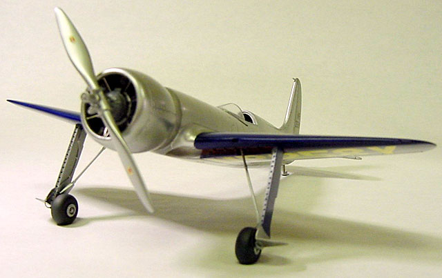
final assembly. The prop itself is cast in white metal, and will need to
be primed, sanded, and painted to achieve the best finish. The back of the
propeller was not painted when the aircraft had the short wing, so I
painted the entire prop aluminum.
The H-1B had a number of short, fairly straight engine exhaust stacks
under the cowling, running to the rear edge of the cowling itself. These
are not replicated in the kit, except for the three exhaust pipes on the
right side of the fuselage just behind the cowl. There is only a narrow
gap between the front of the fuselage and the cowling, too narrow, in
fact, to add the additional exhaust pipes.
I narrowed down the very front of the fuselage, where it “necks down”
and ducks under the cowling to give enough room to add these exhaust
pipes.
Using photos, I added the additional pipes after priming the model.
They are just visible if you look for them; NOIX chose to leave them off
altogether, and you may choose to do the same. This is how these pipes
looked before the engine cowling was glued in place.
I wanted to make the finish on this model as smooth as possible, and
glossy within the limits of the scale; I think an all-out, automotive
gloss finish on a smaller-scale aircraft model looks too toy-like. I
consulted with some of my local model geek buddies who are experts in
gloss finishes, and followed their advice. First, I bought some Plasti-Cote
(brand name) white, sandable, auto body primer (a lacquer-based product);
it is important that the primer is sandable and lacquer-based, especially
if you plan on using the relatively new Alclad II metalizer finish. I
sprayed the entire model (and later, the landing gear, prop, and assembled
engine cowing) with this primer. Remember spray painting from a can? The
airframe looked like a mess when I finished with the primer, with some
spots just covered and others almost running with excess paint.
Fortunately, this stuff dries quickly, so the next step was to sand down
and polish the primer.
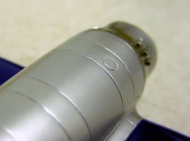
The primer filled in many of the minor surface imperfections as it was
supposed to do; but before you can successfully paint a gloss finish over
it, it must be polished. I used a 6000-grit sanding pad to smooth down the
surfaces, and then switched to Novus brand plastic polish to bring the
primered surface to a glossy sheen. In my opinion, this polishing is the
real secret to obtaining a nice, metallic finish in situations like this
where a primer coat is required. Here are the engine cowling and
propeller; the cowling shows what the entire airframe looked like just
before the color coats were started. The propeller and the entire cowling
were later painted with Alclad II Aluminum.
A friend of mine provided the automotive paint and reducer (that is,
thinner) I used in this project, but any good gloss paint/metalizer that
you are comfortable with should work fine. I painted the whole model with
my mixed, dark gloss blue, laying on a “mist” coat and then three wetter
coats of paint (allowing the paint to dry to the touch in between, of
course!). I got some orange peel, as I expected, since I am still learning
how to paint gloss finishes. The trick is to rub down the paint when it’s
completely dry with polish, which takes away the orange peel and leaves a
smooth, glossy surface. I practiced each step in this process on some
scrap before working on the model. I then masked off the wings and sprayed
silver for the polished natural metal on the fuselage. The area just
behind the cowling was exposed to direct exhaust and it shows as a
different shade in pictures. I painted it in a steel shade.
I also wanted to make the fabric-covered areas look slightly different
from the polished aluminum look of the fuselage. I masked off the
fabric-covered rudder, elevators, and a section on the bottom of the wing
center section and painted them a slightly darker shade of aluminum. I
then painted them clear acrylic gloss, added the decals on the rudder and
sprayed it with a second clear gloss coat, then finished all these areas
with a thin coat of clear satin.
I also masked off a few panels on the fuselage and gave them a coat of
clear acrylic satin; it makes the light reflect differently from the
surface and produces a subtle effect that I like very much. Finally, I
masked off the outer portions of the landing gear wells, painted them a
light reddish brown, and then added a wash of darker brown to accentuate
the crevices and create a semi-gloss, varnished wood look.
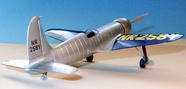
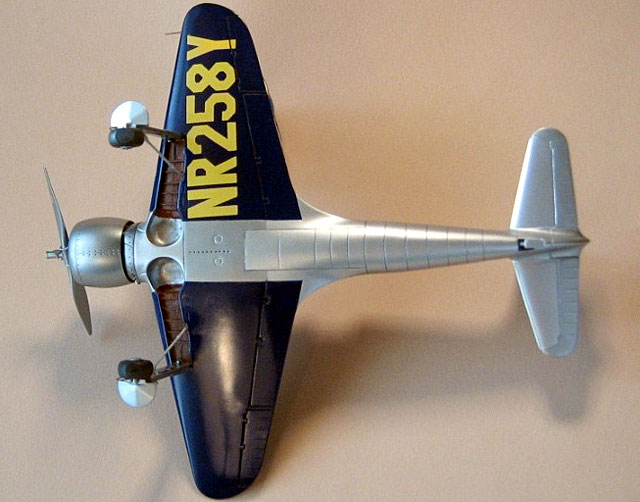
The kit-supplied decals for the wing registration numbers looked too
light to me, and I also thought it likely that they would be translucent
when applied. I created artwork and had dry transfers made. This is an
expensive thing to do, but the dry transfer letters are completely opaque
and at the same time extremely thin. I laid them down and burnished them
on. They look terrific, but they were almost flat in luster. I masked off
the wings and painted them with a couple of coats of clear acrylic gloss,
then polished them out to give them a smooth, even shine. I did not polish
the ailerons to give them a tonal difference- glossy fabric coating that
is just a little flatter than the rest of the wings is what I was aiming
for. I used the kit decals for the numbers on the vertical tail and the
propeller logos; I cut them out individually and used some Microscale
setting solution, and they worked very well with no silvering. I used an
oil wash of Payne’s gray for the elevator and rudder panel lines, a light
gray for the fuselage panel lines, and straight black for the flap and
aileron panel lines on the wings.
I painted the wheels and tires, mounted them along with the landing
gear, pitot tube, and windscreen, and voila! A handsome Hughes H-1B was
complete.
-
Photos of the Hughes H-1B and of the
replica aircraft from Jim Wright’s H-1B web site
-
Historical Aviation Album, Vol. 16: “Howard
Hughes and the Hughes Racer,” by Paul R. Matt
-
Photos of the aircraft as it is currently
displayed at the National Air and Space Museum
Bill Bosworth and Mike Bays, for invaluable reference information and
assistance, Jonathan Strickland, for the current photos of the H-1B in the
National Air and Space Museum. The family of Jim Wright, for his creation
of the H-1B replica and sharing information through his web site. Some of
the model photographs courtesy of Wayne Funderburk.
Click the
thumbnails below to view larger images:
Model, Images and Text Copyright © 2004
by Jim Kiker
Page Created 05 January, 2004
Last Updated
17 March, 2004
Back to
HyperScale Main Page |
 Home |
What's New |
Features |
Gallery |
Reviews |
Reference |
Forum |
Search
Home |
What's New |
Features |
Gallery |
Reviews |
Reference |
Forum |
Search