|
LVG C.VI
Building the 1/48 scale
Blue Max Kit
by
Bucky Sheftall
|
 |
|
LVG C.VI |

Blue Max
1/48 Scale LVG C.VI is available
online from Squadron
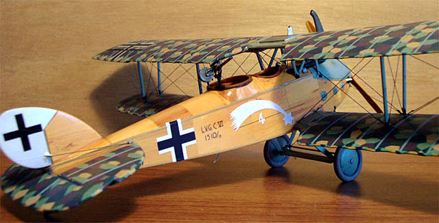
The LVG C.VI was one of the
last German two-seater designs of World War One to see major production.
Entering the war too late to make no more than a passing contribution to
the Kaiser’s war effort, the C.VI nonetheless soldiered on through the
1920s and ‘30s in European civil aviation as a converted small airliner,
generally holding three passengers plus pilot.
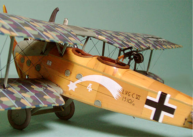
Produced by Luft-Verkehrs-Gesellschaft mbH of Berlin-Johannisthal, the
aircraft was powered by a 240 hp Benz Bz.IVű. Like many other German
two-seater designs, it featured a slab-sided fuselage of formed plywood
construction, which was generally left in a clear-varnished condition,
giving the woodwork its characteristic rich amber tone. Standard armament
was a synchronized Spandau firing forward through the propeller arc, and a
ring-mounted Parabellum in the observer’s station for rear defense. Some
C.VIs were equipped with Wurfgranate grenade and/or Fliegermaus bomblet
racks for trench strafing, while others were used in the photo recon role,
using a camera that shot pictures through a sliding trapdoor in the floor
of the observer’s compartment. The C.VI could also be equipped with a
Morse code radio transmitter, as evidenced by the small weighted antenna
poking out of the underside of the fuselage.
Top speed was around 150kph, and the aircraft was said to have had decent
manoeuvrability for a machine of its type and size.
Blue Max 1/48
Scale LVG C.VI
|
This is a 2001 Blue Max
offering – yet another fine limited run 1/48 simple injection kit by Chris
Gannon.
Flying and control surfaces,
fuselage main parts, tailskid, engine crankcase and propeller are in a
soft, light gray plastic. Bulkheads, guns, engine cylinders and plumbing,
cabane struts, seats, landing carriage and other detail parts are in white
metal. A length of plastic strut material is provided, as modelers are
required to either cut interplane struts from this or use alternatives (as
per my SOP for biplane modeling, I opted for flattened brass tubing
instead for added strength).
The ailerons are provided as separate pieces, which allows the modeler to
position them as desired. A nice touch.
A thin decal sheet is
provided, with two aircraft options. Both options are for aircraft from
unknown units, although photographic record of the aircraft survives, so
don’t worry, the markings are accurate. The decals respond well to mild
setting solution.
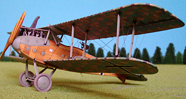
Both option schemes call for wings, control surfaces and horizontal
stabilizer to be covered in German 5-color lozenge, but the appropriate
decals are not provided in the kit, so modelers have to fend for
themselves in this department. There are a good selection of aftermarket
lozenge decal sets available. Eagle Strike, Pegasus and the now
unfortunately out of production Aeromaster sheets come to mind here. If
you are lucky to have a decal-capable printer and the appropriate drawing
software, or if you are patient (and insane) enough to handpaint, you can
of course make your own.
As usual with Blue Max kits, the exploded view “instruction sheet” – if it
can be called that – is not exactly exhaustive. As Mr. Gannon himself
recommends, it is strongly advised for “modelers to avail themselves of
the Windsock Datafile (No.17)” to help them build the kit. Sound advice
indeed. I have become so dependent on Windsock reference material over the
years that I would not dream of approaching any WWI subject – let alone a
Blue Max kit – without the appropriate Datafile on hand.
Fuselage
While on the subject of the
Datafile series, initial dryfitting of the fuselage halves provided in the
kit and comparison with the 1/48 plans in Datafile 17 showed that the Blue
Max fuselage was a few scale inches too wide, so one of the first
construction steps I took was to thin the fuselage halves down
appropriately. Subsequent dryfitting showed that the modified fuselage was
right on the money.
That was the good news.
The bad news was that now
none of the white metal fuselage bulkheads fit. Neither…gulp…did the
Parabellum ring.
Time to throw the kit against the wall and scream bloody murder? Perhaps
this might have been the case on a morning with more caffeine coursing
through my veins, but luckily for the LVG, I had run out of espresso. So,
it was out with the Evergreen stock and the contour gauge for some happy
hours of bulkhead cutting, sanding, and dryfitting until I got an
arrangement with minimal gaps. I glued the bulkheads in place and added
some extra planking on the floor. Other scratchbuilt items inside the
fuselage include:
-
Fuel tank, which goes under
the pilot’s seat. This was made from plastic stock and strapped with belts
cut from wine bottle foil. The tank was painted red brown (Tamiya 64) and
drybrushed with copper metallic paint.
-
Control column was made of
brass rod, with a brass wire handle ring soldered to the top. Wood handle
grips were fashioned from Evergreen stock.
-
Observer’s seat, camera
trapdoor and diagonal fuselage formers framing the observer’s seat were
cut from Evergreen stock
-
Ignition plugs and pushrods
on the engine were done with 0.2mm brass wire and 0.3mm rod, respectively.
-
Instrument panel – like the
bulkheads – was cut from plastic, and the instruments themselves were from
the excellent Eduard WWI Instrument set. Pilot and observer seatbelts are
also Eduard.
Before all the detail pieces
went in, the fuselage halves – with new bulkheads in place – were sprayed
tan and streaked with red brown. Beams and formers were also painted red
brown. When all of this was dry and cured, I gave all the structural
internal woodwork a very thin “Gregg Cooper” wash of Van Dyke Brown
artist’s oil and Zippo lighter fluid.
Once the details and engine were in place, the fuselage halves went
together, and now it was time to sweat out the gun ring problem.
The gun ring was a delicate and surprisingly challenging item to
scratchbuild. I used a draftsman’s template to trace concentric circles of
the appropriate diameters, then cut out and sanded the edges of the inner
ring until everything there was round and smooth. After that, I cut and
sanded around the outer ring, constantly comparing with the Datafile plans
and reference photos.
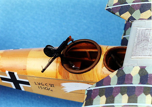
Evergreen stock would have been too delicate for this piece, so I used
Tamiya 1mm sheet instead, as I usually do when more strength than subtlety
is required for a scratchbuilding task. Even with Tamiya strength on my
side, however, I was leaving nothing to chance. After the inner circle was
cut out, I kept the ring on my finger – literally – while I finished the
piece to prevent it from being crushed by rough handling as I cut and
sanded. Once I had a good basic ring to work with, I filled out the
contours with Evergreen stock and Milliput.
Wings and Stabilizer
The wings required a bit of
prep to get them up to snuff. Some pretty gnarly sprue attachment points
had to be cleaned up, and all of the scalloped trailing edges had to be
thinned and trimmed. Patience and a very sharp blade are required for this
job.
Assembling the kit as-is presents the modeler with the disquieting
prospect of attaching the lower wings to the fuselage by butt joint, i.e.,
simply gluing the wing root ends to the fuselage and hoping this stands up
to the rigors of further construction and handling. As I generally prefer
my model engineering to be able to handle anything up to and including
light vehicular traffic, I wasn’t about to leave this critical area to the
vagaries of mere liquid cement and styrene.
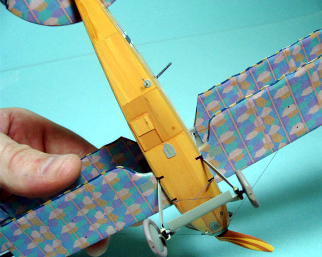
I drilled holes in the wing
roots and inserted 1mm brass rod, cutting this to leave pegs about 3 or
4mm long. Consulting the Datafile for location, I drilled commensurate 1mm
holes in the fuselage, lined everything up and slathered on the liquid
cement. I built a simple jig of two lengths of 5mm plastic beam stock
affixed to a wooden board with double-sided tape with enough space so that
the wingtips – resting on the beams -- would be pushed up to provide the
proper (and rather shallow) dihedral as the joints cured. I set the
assembly on top of this, centered the fuselage carefully, put a paint
bottle on the fuselage for weight, then left the rest of the job up to
time and gravity. I had a good strong bond by morning.
 The top
wing posed a problem of a different nature, as the center section provided
in the kit is white metal, rather than the expected plastic. This meant
that liquid cement was out as an adhesive option, necessitating the use of
mechanical rather than chemical means. The top
wing posed a problem of a different nature, as the center section provided
in the kit is white metal, rather than the expected plastic. This meant
that liquid cement was out as an adhesive option, necessitating the use of
mechanical rather than chemical means.
I ended up drilling holes to
take 1mm brass rod, then made the join with epoxy. In the final assembly,
most of the strength will be provided by the interplane struts and nylon
fishing line rigging, so the join here – in contrast with the lower wing –
does not have to be superstrong.
Last night’s wing jig was
put back to work (remembering to compensate for the height of the radiator
grill under the center section), and after the 30-minute epoxy had set up,
I now had a good top wing.
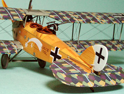
At a glance, two features of
the LVG are most noticeable: the lozenge fabric wing covering, and the
amber-toned plywood fuselage. I approached the first item through the use
of scale lozenge roll stock drawn up on my computer with graphics software
and printed on an ALPS printer. On a somewhat melancholy note, the LVG
project used the last lozenge batch I printed up before suffering the
double whammy of losing the data in a computer crash and having the ALPS
go kerflooey on me. Needless to say, I exercised plenty of TLC applying
the material to the LVG flying surfaces after the “plywood” job was taken
care of.
The “plywood” decal was another exercise in homebaked decal fun, but
outside of an airbrush, there was nary a hint of hi-tech involved. Using a
technique taught to me by my good WWI Mailing List buddy Steven Perry, I
sprayed an A4 sheet of clear decal film (DON’T use white – the edges will
show after you make cuts) with slightly varying tones of warm tan acrylic
(in this case, I started light at one end of the sheet, and gradated to a
darker tone by the other end). After this had dried and cured thoroughly,
“grain” was applied to the “wood” by streaking with a darker red-brown
applied with a course, stiff, half-dry brush, keeping the streaks roughly
parallel. For accenting, very dark brown “knots” and stippling can be
applied here and there with a fine-tipped brush, but don’t go overboard.
Finally, to seal the paint and make it softener-safe, I oversprayed with
Microscale Decal Film.
The trick to making the plywood look convincing is to cut fuselage panel
sections from non-adjacent areas of the decal sheet, so as to give tonal
and grain pattern variation. Grain direction can also be varied, i.e., it
can run vertical in one panel, then horizontal in the next. Check
reference photos for plausible schemes.
When cutting fuselage sections, it is not necessary for the decal pieces
to be precise, because you will be fine tuning the decal edges with an art
knife (make sure to use NEW blade) to trim the panel lines AFTER the
decals have gone on. Make sure not to drink too much coffee before this
task, as it calls for a steady hand and nerves of steel!
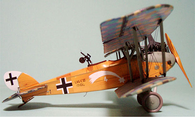
Cowling, struts, access panels, louvres and landing gear were painted in a
custom-mixed color you could call a kind of washed-out RLM 02. RLM 02, of
course, was an oft-used Luftwaffe shade and a generic utility color the
German military still uses and has used for the better part of a century
for everything from aircraft undercarriage to canteen cups and blankets.
Kind of a Teutonic version of G.I. OD green, I suppose. In the case of my
LVG, I felt that this shade, mixed with a cooler light gray, gave a good
approximation of the color represented in the LVG Datafile book and, more
than anything, a suitably “Germanic” feel to the paint scheme that stayed
on the warmer, greener side of the almost RFC/RAF Battleship Grey many WWI
modelers use for German metalwork.
All major painting was done with Tamiya acrylics, thinned for spraying
with isopropyl alcohol and Gunze lacquer thinner at about a 5/4.5/0.5
ratio. Detail painting was handbrushed where necessary with Tamiya and
Humbrol enamels. Panel washes are artists’ oils (mostly Burnt Umber or Van
Dyke Brown) thinned with mineral spirits or Zippo fuel.
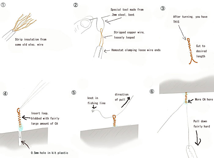
Rigging was done using a
technique taught to me several years ago by Mr. Jiro Hashimoto of Osaka,
Japan, who is widely regarded as the hands-down best WWI modeler east of
the Czech Republic and west of California.
His technique uses ordinary
nylon monofilament fishing line run through semi-functional turnbuckle
loops scratchbuilt from copper wire in the 0.1-0.15mm range. Refer to the
attached diagram for the details (note: final operation after completion
of Step 6 is to cut the line after second CA bond has dried). This process
must be repeated for each point-to-point rigging segment in the model.
Tedious, perhaps, but the
results are a nice payoff. One point of warning: the turnbuckles are soft
copper – not tungsten steel – so be careful not to bust them out by
applying too much stress in the slack-pulling phase.
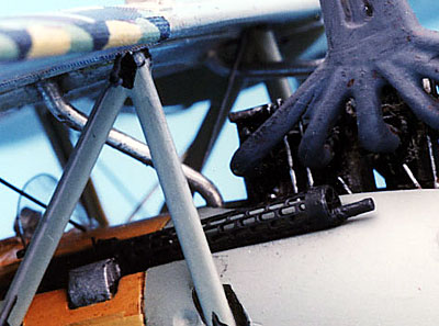
“Laminated” prop effect was
done by spraying with light tan, masking with very thin strips of 3M
mending tape (green plaid type) and overspraying with a darker shade.
Niendorf prop decals thanks to Shane Weier from sunny Australia, an
e-buddy of many years from the WWI Mailing List (
www.wwi-models.org ).
Pushrods and ignition wires on engine are done with 0.2mm brass rod.
Radiator pipes are 1mm solder bent to shape.
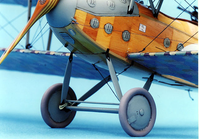
Black reinforcement plates around landing gear and at strut ends are done
with cut sections of black decal. This technique simply cannot be beat for
a job like this, and as long as you have a sharp knife, a straight edge
and some decal stock on hand and you know how to mix paint, you can custom
create pieces for any need. In many cases, I suspect it may even be closer
to scale thickness than PE parts, especially after these are attached to a
model with CA or epoxy adhesive. Not surprisingly, the cut decal technique
is one I find myself turning to more and more often in recent WWI projects
to represent small metal fixtures.
I found this Blue Max kit –
in common with all the previous ones I have done – to be a challenging and
rewarding build. I recommend it highly to anyone with a few biplane/WWI
kits under his or her belt, feels ready for something a little different
and wants to try out the plywood decal technique.
Finally, I would like to thank all of the people who helped me with advice
and materiel during this project, especially Steven Perry, Ken Acosta,
Shane Weier, Robert Karr and the other members of the WWI Mailing List. A
kinder, more helpful and erudite bunch of biplane fanatics you would be
hard pressed to find!
-
Windsock Datafile #17, PM
Grosz, Albatros Publications, 1989
-
LVG Special Feature by Ray
Rimell and Maurice Brett, Scale Models, January 1973.
-
Aftermarket Items Used
-
Eduard WWI Instruments
-
Eduard WWI German Seatbelts
-
Tom’s Modelworks German
Machine Guns
-
Eagle Strike Ribbing Tape
Click the thumbnails below to view larger
images:
Model, Images and Text Copyright ©
2003 by Bucky Sheftall
Page Created 11 October, 2003
Last Updated
17 March, 2004
Back to
HyperScale Main Page |
 Home |
What's New |
Features |
Gallery |
Reviews |
Reference |
Forum |
Search
Home |
What's New |
Features |
Gallery |
Reviews |
Reference |
Forum |
Search