|
Messerschmitt P.1101
by
Peter Kormos
|
 |
|
Messerschmitt Me 1101 Night Fighter |

HyperScale is proudly supported by
Squadron
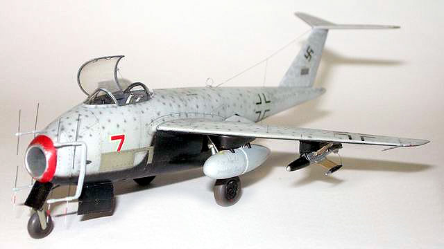
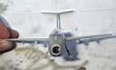
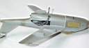
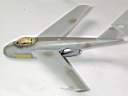
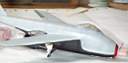
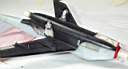
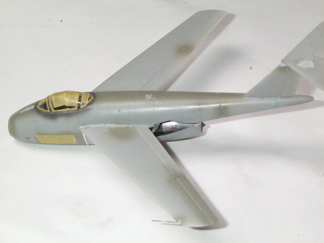
This is Dragon's 1/72 scale Messerschmitt P.1101 kit portrayed as an imaginary
night fighter that flew many missions and suffered much battle damage.
In WWII, aerial radar equipment required a full man on
duty, which made the single seat night fighter concept impossible. Although,
with a little imagination, one can easily accept, that this night fighter served
also as an airborne data acquisition device for a ground unit. Then this ground
unit radioed target coordinates for the night fighters.
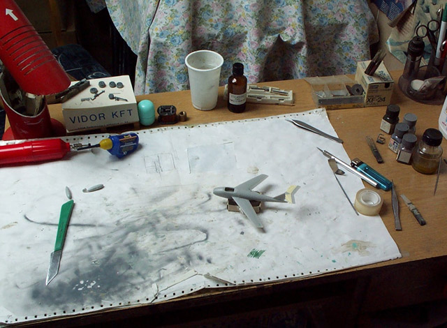
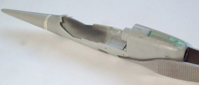
One of the first happy moments, 2nd June, 2002, a few days after the kit was
bought. The main parts were held together with adhesive tape to see how the kit
would look. I used yellow tape to protect the surfaces when sanding the trailing
edges. On the photo, you can also see my workbench with sort of little mess on
it!
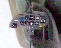
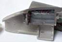
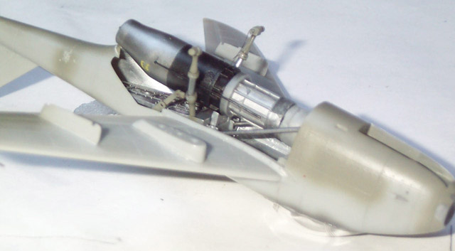
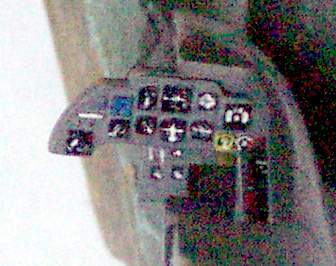
Cockpit
Traditionally, I started the constructin with the cockpit. The photo etched
instrument panel was glued to the flat face plastic backing. With a pointy needle,
I've carved little details to the lower part, and painted the whole instrument
panel with a fine brush.

I could find all of the main parts - seat, control stick, instrument panel
- on the sprue, but it was a big surprise when the construction guide called
for gluing the side panels in about 60 degrees instead of horizontally. I haven't
seen anything like that on the early jets, so I decided to fabricate the side
consoles from soda can and use them as a base for the photo etched side panels.
Being a plane with nose wheel, I had to add strips of lead plate as a counter
balance. You can also note the big gap at the side of the nose gear bay that
I had to fill with stretched sprue and putty.
The rudder pedals were also completely flat, so I've detailed them with strips
of soda can and copper film.
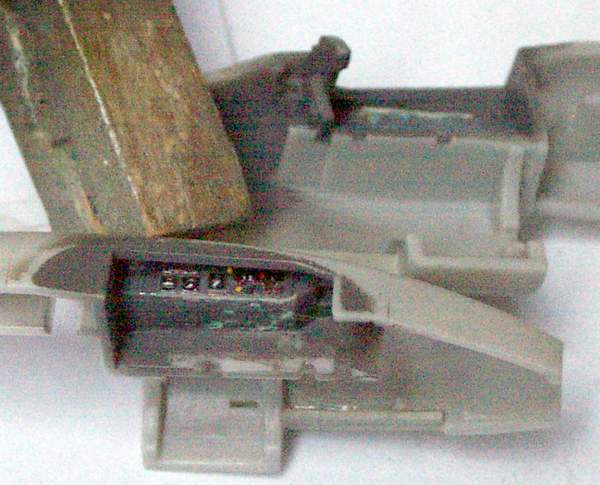
 There's also a little kit's part for the gunsight, but it wasn't molded from
transparent plastic, so I couldn't use it. I've scratch built one from flattened
plastic and the glass was cut out from the celophane plastic bag - used for
separating the different sprues in the box. After gluing the two reflex glass
plates in place, I've carefully tinted the front one with highly dilluted black
paint. I've added little levers and knobs to the side panels from copper wire,
and detailed the control column with adding little electric wires to it. There's also a little kit's part for the gunsight, but it wasn't molded from
transparent plastic, so I couldn't use it. I've scratch built one from flattened
plastic and the glass was cut out from the celophane plastic bag - used for
separating the different sprues in the box. After gluing the two reflex glass
plates in place, I've carefully tinted the front one with highly dilluted black
paint. I've added little levers and knobs to the side panels from copper wire,
and detailed the control column with adding little electric wires to it.
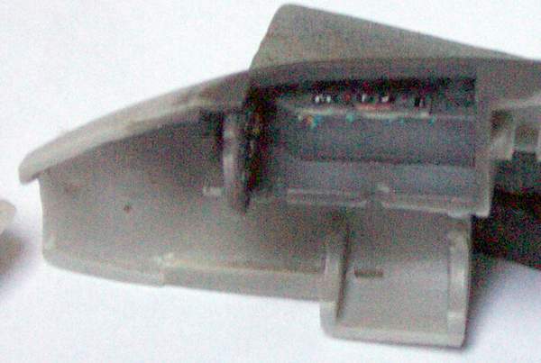
The
pilot's seat is quite good, I've only thinned down it's side walls to achieve
a more realistic look. After paining the seat, I've added the really nice seat
belts from Eduard.
Detailing the Exterior
The biggest problem of most 1/72 scale Dragon kits is the orange skin on
the parts. It's not really notable on the smaller parts, but on the bigger ones
like the wings is really annoying. It wasn't complicated to sand down the orange
skin, but took quite a while. Then, I've applied some putty to the sink marks
on the fuselage halves that were revealed by the sanding. The contour for the
guns are present on the fuselage, but I had to carv in the the little elliptical
depressed in front, and cut out the spent cartridge ejection ports on the bottom.
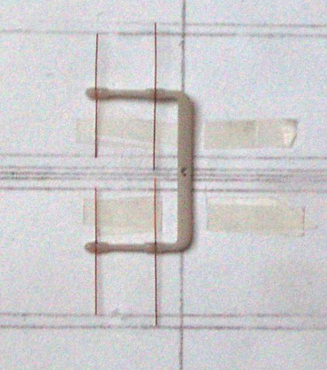
There's a little photo etched DF loop antenna included in the kit, but I found
it too flat and wide, so I decided to make my own one from a thin strip of copper
film. I've also had to create the teardrop shaped fairing for the DF loop on
the spine of the fuselage. Luckily, I didn't brake the pitot tube on the port
side wing, but later I've decided to replace it with a little hypo needle.
Part of the detailing was to thin down side walls and gear doors.
There are photo etched radar blades included in the kit, but they are too wide
for scale just like the DF loop was. So I decided to cut copper wire to size
and glue it to the radar array's frame.

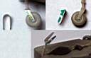
Gear Bays
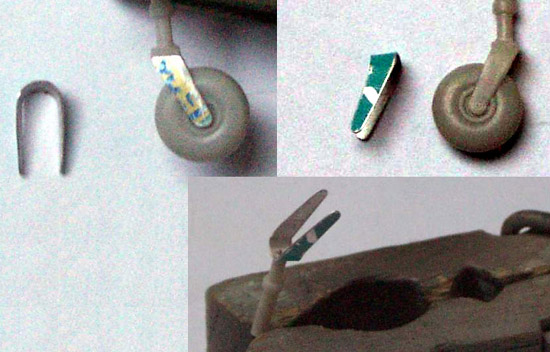
Unfortunately, the nose wheel was molded to the strut, and looked really ugly.
After many unsuccesful attempts to make the thing look better, I've decided
to create a new fork from soda can.
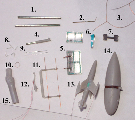
For detailing the kit, I mainly used copper wires,
copper film, soda can and stretched sprue.
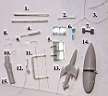
- Replacement for the A16 part in the main gear bay (on the finshed
kit, not much of it is visible)
- pitot tube
- hidrauc lines
- actuator in nose gear
- covers for nose gear
- fork for the strut
- rudder pedals
- support arms for the X-4 rocket
- tie down strips for the main gear
- loop antenna
- radar antenna
- control stick
- X-4 rocket
- drop tank
- teardrop fairing carved from sprue
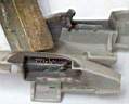
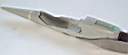
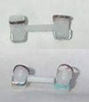
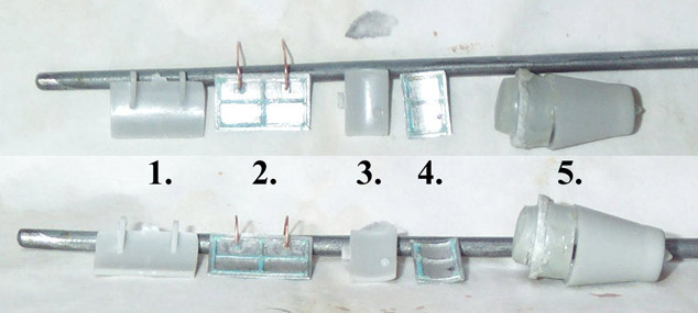
The nose gear covers were over simplified, so I've scratch build replacement
parts from soda can and copper wire.
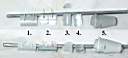 
1., 3. Original parts
2., 4. New ones
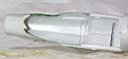
5. I also had to extend the exhaust nozzle with 4.5 mm. This is the extension
part.
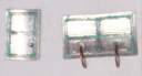
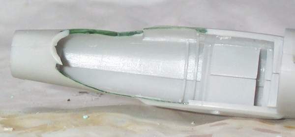
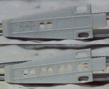
Inside the main gear bay, there was a panel, I've detailed the bit. Drilling
some holes through it made the thing look better.
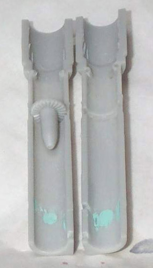
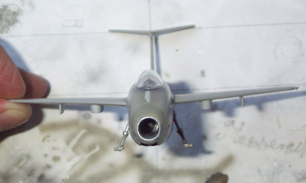
Inside the air intake tube halves, I've found ejection pin marks, that I had
to fill and sand. After dry-fitting the parts, I found out, that they don't
fit perfectly, so I also had to fill the seam after gluing the halves together.

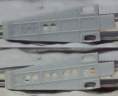
Ordnance
From soda can, I've created little V shaped support arms on the pilons for
the X-4 rockets. I've added the control wires to the rockets and replaced the
engine nozzles with hypo needle. I've added copper belts to the drop tank, and
fuel pipes from copper wire.
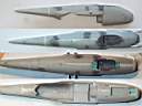
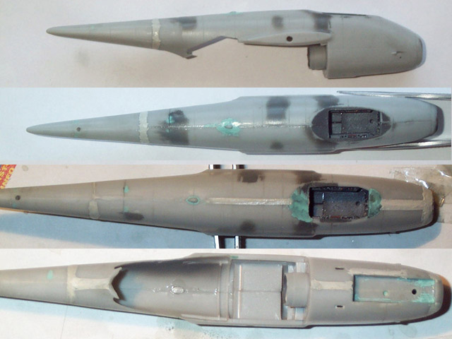
The fuselage parts fit well, but all the joints needed a little filler. The
fit was a bit worse in the nose gear bay, where I used stretched sprue and lots
of filler.
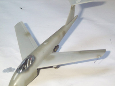
After gluing the wings and stabilizers in place, I've checked their alignment.
I've decided to leave the engine covers in place, so I didn't have to detail
the engine much. I only added two little wires to the end of the engine, and
painted a little serial number on the exhaust nozzle to spice up the thing.
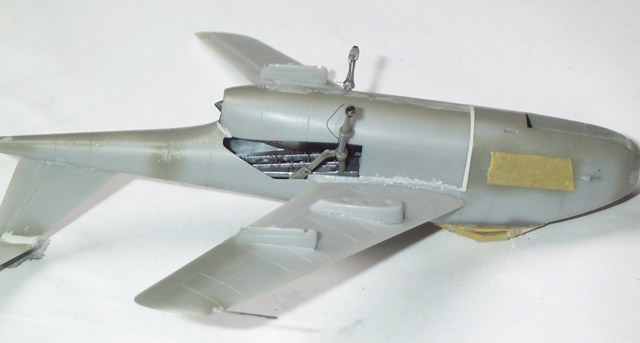
When most of the filling and sanding was done, I've painted over the putty
with RLM02, which also served as a final cote for some areas. Here and there,
RLM02 revealed some little imperfections, that I had to fill again.
Before I've started to apply the camo, I appled Tamiya masking tape to the
canopy and panels that remained in RLM02.
This kit served as a test bed for trying out different materials for masking.
I've used Tmiya masking tape, Humbrol masking liquid, toilet paper, aluminium
foil, adhesive tape, and also normal paper.
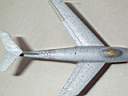
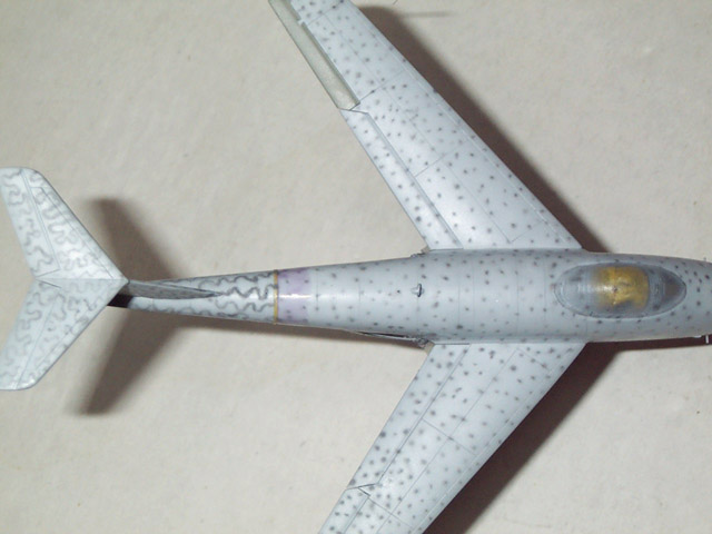
After examining night fighter camo scemes of Me262s and He219s, I've designed
the pattern of RLM22/76/75 on my PC. Of course, that was only a guide for painting,
and later I made minor changes to it.
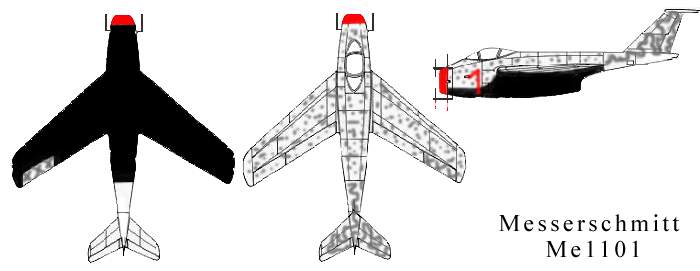
In my theory, the tail section was cannibalized from another Me1101 and the
port side panel and aileron was field repaired, and left in RLM02.
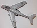
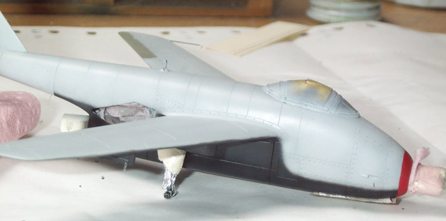
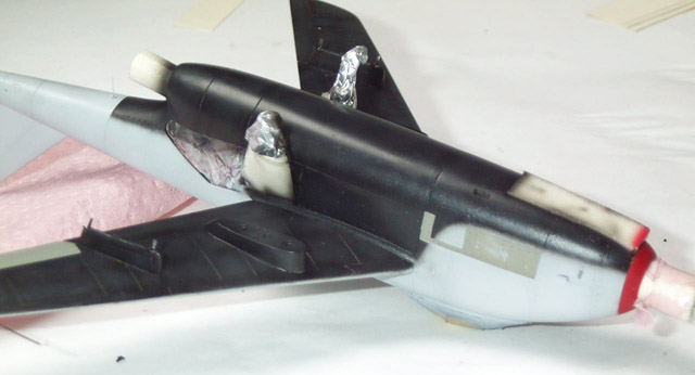
First I've sprayed RLM76 then the black. Spraying balck was really hard, and
needed extra attention, since the contrast between the black and RLM76 was big.
Then came the RLM75, where I used highly dilluted paint and low air pressure.
Luckily, I could spray 99% of the the mottle and squiggle well. Where the paint
run or the mottle didn't happen to be good, I've oversprayed with RLM76 and
reapplied RLM75. For all the camouflage colors, I've used Gunze and Tamiya acrylics.
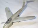
I've sprayed a coat of gloss varnish, and applied the decals. Then came a
mist of dull cote and glued the radar arrays, canopy hatch and wire antenna
in place. I've added paint chips and fluid leaks here and there, and the kit
was finished.


Model, Images and Text Copyright ©
2003 by Peter Kormos
Page Created 28 March, 2003
Last Updated
17 March, 2004
Back to
HyperScale Main Page
|
 Home |
What's New |
Features |
Gallery |
Reviews |
Reference |
Forum |
Search
Home |
What's New |
Features |
Gallery |
Reviews |
Reference |
Forum |
Search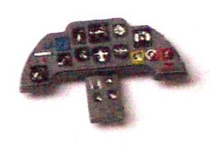


