|
Dassault Mirage IIIRS
by
Thomas Muggli
|
 |
|
Dassault Mirage IIIRS |

HyperScale is proudly supported by Squadron
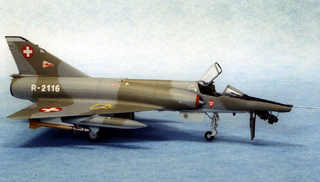
At the end of 2003 a significant chapter in the history of the Swiss
Air Force will come to an end. The last Dassault Mirage IIIRS will be
retired after 36 years of service.
The career of the Mirage in Switzerland began with what is known in
Switzerland as the “Mirage scandal”. It started with the decision by the
Swiss Air Force leadership to equip the Swiss Mirages with an American
made radar and missiles, instead of the standard French equipment.
Unexpected problems with the integration of the American systems and the
French airframe led to massive cost overruns. The Swiss parliament did not
take kindly to this news, and promptly denied the additional funding
requested by the Swiss Air Force brass. As a result, the planned purchase
of 100 aircraft had to be cut to only 56 (36 Mirage IIIS interceptors, 18
Mirage IIIRS reconnaissance aircraft and 2 Mirage IIIBS two seat
trainers). The scandal also led to the resignation of the chief of staff
of the Swiss Air Force, and hampered procurement of new aircraft for
decades to come. However, once the Mirages entered service, they proved to
be a good investment. The sleek, delta-winged jets proved to be top-of-the
line fighter aircraft for many years. Technology advances and changes in
military needs caught up with the Mirages in time.
A few years ago the interceptors were replaced by F/A-18 Hornets, and
now the Mirage IIIRS and BS are falling victim to the budget axe.
Since they are now fading into history, I wanted a Mirage IIIRS for my
collection of Swiss Air Force Aircraft in 1/72 scale. There have been
several Mirage kits available over the years, none of which were of
particularly good quality. Probably the best Mirage kits currently
available are from High Planes Australia. I used these limited run kits to
build my Mirage IIIS and BS. But this is a different story for a different
day...
I had three Mirage kits sitting on my shelf, one of which would yield my
RS. I quickly discarded the Dagger kit from PM Turkey which is just awful.
Left were: a Heller kit, and a Revell Germany kit which I had bought in
Switzerland some years ago. Both kits show their age and are not up to
today’s standards, but offer the option the build a reconnaissance Mirage.
I chose the Revell kit because I liked the surface details better.
However, much work lay ahead to get the result I was looking for.
When building an outdated kit, aftermarket detail parts can be very
helpful if not essential. In the case of my Mirage IIIRS I used a Hi-Tech
resin detail set. The largest part in this set is the combined cockpit
tub/front wheel well. I started by removing all molded on plastic from the
inside of the cockpit area of the fuselage halves. The resin part was
carefully shaped until an acceptable fit was achieved and the fuselage
halves could be closed without leaving a gap. However, before grabbing the
glue, I painted the cockpit, instrument panel and the ejection seat, all
of which came from the resin set. I also modified the main wheel wells to
deepen them and added details to match the better detailed wheel wells of
the High Planes kits which I was building at the same time. After joining
the fuselage halves, I finished the assembly of the fuselage by adding the
wings and vertical stabilizer.
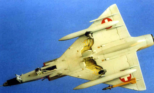
Camera Nose
I had a number of photos of the opened camera nose of the Mirage IIIRS.
I wanted to show off the business end of the RS on my model as well. The
kit parts of the camera nose are split top and bottom. First, I cut a 4mm
section off the tip of the bottom part and glued it to the top part. The
top part was then joined to the fuselage. I made the top and sides of the
camera bay from sheet styrene. Next, I added some plumbing made from wire
to the inside of the camera bay. To replicate the camera window at the tip
of the nose, I flattened the tip of the nose a bit and glued a small round
piece of clear styrene in place. Finally, the various parts of the nose
section were shaped and smoothed with a sanding stick and any gaps filled
with superglue.
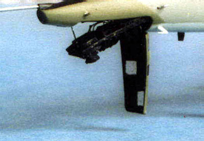 The
second subassembly I worked on was the camera rack, which is lowered from
the camera bay to allow the films boxes to be loaded and removed. The RS
rack carries three cameras. The rack’s frame is not symmetrical, since the
rear camera faces port, the middle camera starboard, and the forward
camera straight down. For the long sides of the camera rack I cut two
strips from a flat piece of hard styrene which I found in my spares box.
Using a sharp blade and small files I gave each side a slight S-shape
according to my references. The remaining parts for the rack were cut from
styrene strip. The rack was assembled and glued with superglue paying
careful attention to proper alignment. The cameras were shaped from
laminated pieces of plastic scrap. For the lenses I used pieces of clear
sprue polished at one end to give them a glassy look. After the cameras
were installed, I added copper wiring. The whole assembly was painted flat
black and dry brushed with aluminum. The
second subassembly I worked on was the camera rack, which is lowered from
the camera bay to allow the films boxes to be loaded and removed. The RS
rack carries three cameras. The rack’s frame is not symmetrical, since the
rear camera faces port, the middle camera starboard, and the forward
camera straight down. For the long sides of the camera rack I cut two
strips from a flat piece of hard styrene which I found in my spares box.
Using a sharp blade and small files I gave each side a slight S-shape
according to my references. The remaining parts for the rack were cut from
styrene strip. The rack was assembled and glued with superglue paying
careful attention to proper alignment. The cameras were shaped from
laminated pieces of plastic scrap. For the lenses I used pieces of clear
sprue polished at one end to give them a glassy look. After the cameras
were installed, I added copper wiring. The whole assembly was painted flat
black and dry brushed with aluminum.
The last part of the camera bay assembly is the cover. My main concern
here was to achieve a realistic thickness for the part. I shaped the
leftover bottom of the camera nose part from the kit to the size of the
cover. The part was then glued to the tip of a wood dowel, which was
fastened in a vise. I heated a piece of clear acetate sheet over a candle
and stretched it over the kit part. After cutting the new part from the
acetate sheet, I had a realistically thin cover. Small strips of styrene
were added to the inside of the cover to represent the struts seen on the
real item. I used small pieces of bare metal foil to mask the camera
windows from on the outside of the cover. Only three windows are actually
transparent. These were also masked on the inside of the cover, paying
attention to proper alignment with the masking already in place on the
outside. The inside was sprayed flat black while the outside was painted
light gray/dark green according to the aircraft’s camouflage pattern.
More Details
The rest of the model was assembled according to the kit’s
instructions.
One characteristic item I paid special attention to were the numerous
small air intakes on the bottom of the fuselage and wings as well as the
two larger ones on the upper fuselage. These were not properly represented
on my kit (or on the High Planes kits for that matter). I made
replacements as follows: I cut a thin strip from a 1 mm styrene sheet.
Using a sanding stick I shaped the end of the stick to match the shape of
an intake. Then I cut it off 1mm short of the length of the intake. I
repeated this until all the intakes were replaced. From a leftover fret of
a photoetched detail set I cut a 1 mm strip with a scissor. Using pointed
tweezers I produced a small U-shape at the end of the strip to match the
opening of the intake. The small U was cut off and glued to the front of
the intake with a drop of superglue. After the glue set, I smoothed the
joint between the plastic and brass parts with small files giving the
intake its final shape. Again, I repeated the process for all the intakes.
Admittedly, this is a time-consuming endeavor but the realistic looking
intakes are well worth it.
The kit-supplied landing gear legs were flimsy and inaccurate so I made
new ones from brass tubing and styrene scraps. I used the main wheels from
the Hi-Tech resin set, and the kit parts for the nose gear assembly. Only
a few details were added such as landing lights made from shaped and
polished clear sprue.
I finished my model with acrylic colors. The decals came from various
sources.
The No. 10 Squadron emblem was made on my computer and printed on my
inkjet printer. The registration numbers are dry transfers.
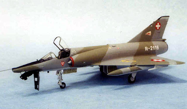
And there it is – my Swiss Mirage reconnaissance bird!
Model, Images and Text Copyright ©
2003 by Thomas Muggli
Page Created 31 August, 2003
Last Updated
17 March, 2004
Back to
HyperScale Main Page |
 Home |
What's New |
Features |
Gallery |
Reviews |
Reference |
Forum |
Search
Home |
What's New |
Features |
Gallery |
Reviews |
Reference |
Forum |
Search