I think this kit has its origins
in old Hawk's offering from the 1950's. The kit basically
comprises two fuselage halves, a single solid main wing and
a few more bits. Sometimes it was hard to distinguish the smaller
parts from the sprue itself.
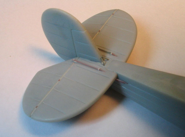
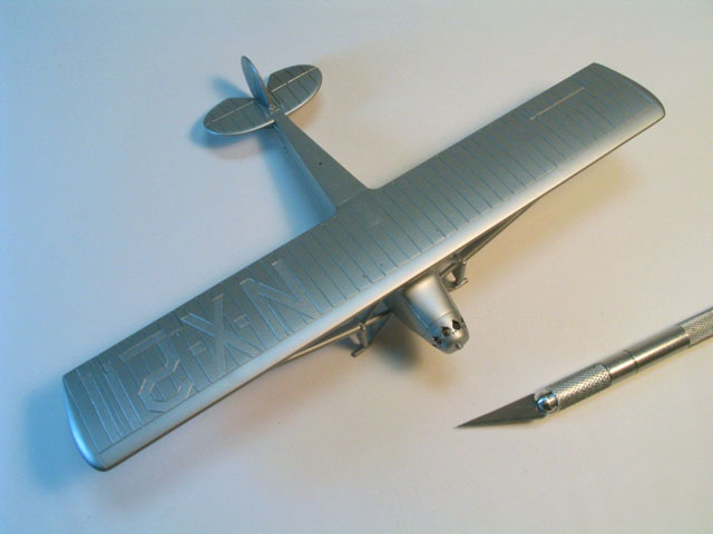
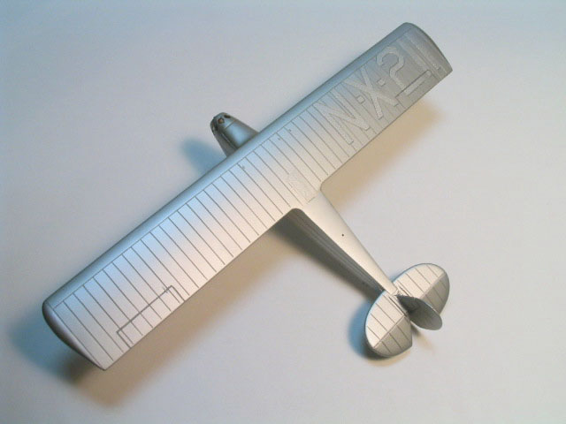
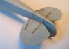
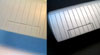
Interestingly, the model
features only recessed panel lines. But in this case they should
be raised, particularly the ribs embossment over the wings. Even
worse, all decal placement positions are also recessed (remember
these?)! Anyway, I was interested in a simple display model and
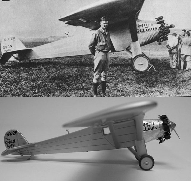
decided not to wait the new Pegasus Spirit of St. Louis in 1/32nd
scale. Besides, the 1/8 J-5 engine will probably shadow much of
the little Ryan.
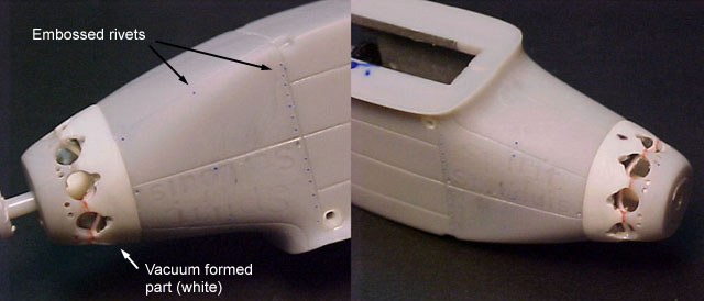
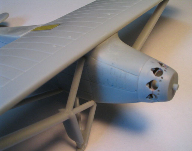
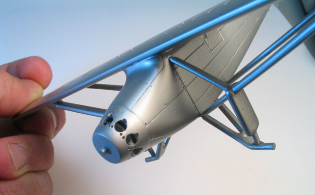
The kit's nose is very bad, mostly because of the crudely
molded cylinder heads.
I vaccum formed a new nose section and drilled the nine holes
for the J-5 engine cylinders (to know how to built your own
vacuum forming table, check my article at Large Scale Planes
website). The holes for the pushrods were also drilled, and this
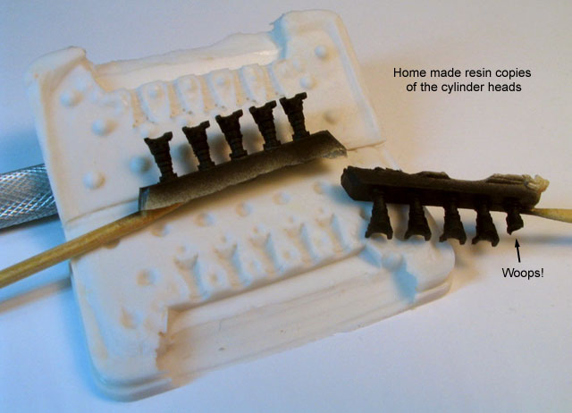
job deserves careful measurement. As for the cylinders, I made
resin copies from an Aires P&W R2800 engine... not exactly like
the J-5 cylinder heads, but they do the trick. After finishing
the model, I discovered a Russian company called Silniki which
produces a resin Wright Whirlwind J-5 in 1/72 scale. Too late,
again.
At this point the fuselage was virtually done. The recessed
locations for decal placement on the cowling and rudder were
filled with super glue and sanded smooth. I then installed the
lateral windows and embossed some prominent rivets on the nose
panels.
Click the thumbnails below to view larger images:
Finishing the Basic Airframe
|
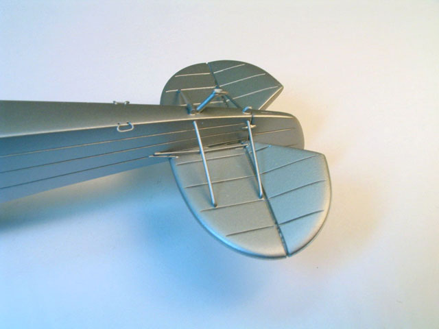
Next, the wing was attached to the fuselage, along with its
supporting struts. The three windows were polished, brush coated
with Future, and masked with Tamiya tape to avoid bluring during
the further handling.
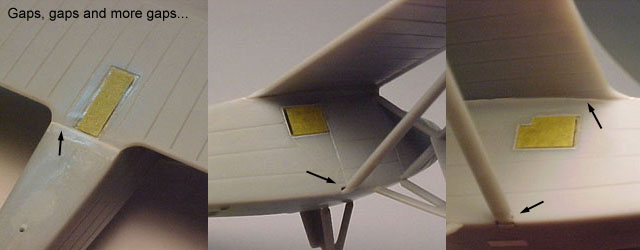
Many spots required filling, but a thick coat of Mr. Surfacer
was enough to handle most of them.
Click the thumbnails below to view larger images:

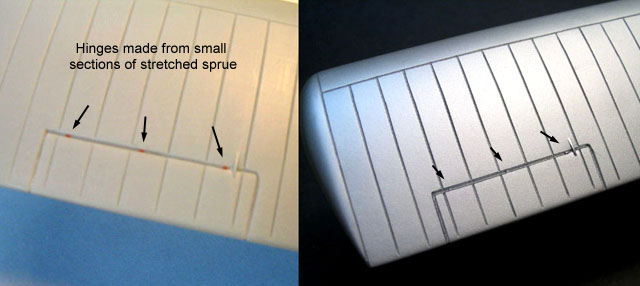
Small sections of styrene rod were glued along the control
surfaces recesses to simulate the hinges. I then applied a very
light coat of Mr. Resin Primer around the nose and tail areas to
look for blemishes. These were the more heavily worked areas,
and I didn't want to leave a rough surface for the metallic
finish that would follow. In any case, the entire airframe was
polished with a piece of soft cloth, including the primed areas.
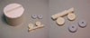
Next, a number of smaller details took my attention. I was
particularly disappointed with the propeller and the wheels. The
former had a spinner molded integrally with the blades, and was
devoid of any surface details. The same applies to the wheels,
with some visible details missing. They laked the teardrop
shaped covers of the landing gear axle, and the stitches which
secured the canvas cover of the spoked wheels are not
represented as well.
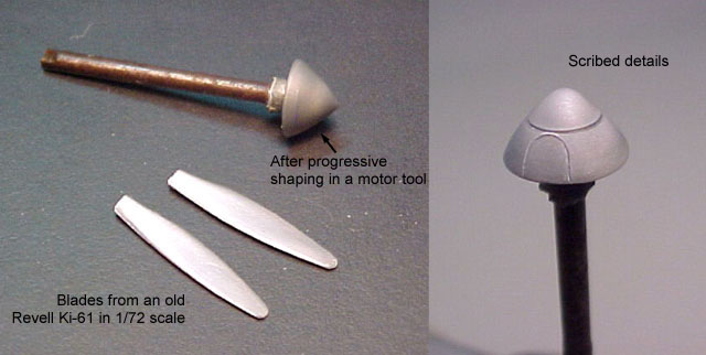
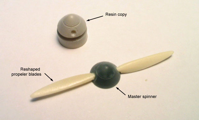
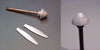
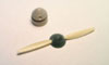
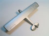
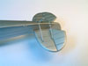
The propeller started its life as an old 1/72 Revell Ki-61
propeller from my spares box. The blades were carefully removed
and the shape of a new spinner was progressively sanded with the
aid of a motor tool, always checking the current profile against
photos. The most difficult part was to scribe the panel lines
around such a double curvature, small part. Several rivet lines
were added to the spinner. Once again, I found too late that
this type of spinner was not used during Lindebergs's famous
flight (in addition, at least three types of spinner were used
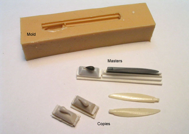
in the Ryan NYP - one of them with a very round tip). I then
reshaped the blades and opted to make molds of everything, just
in case. A master for the wheel tear drop covers was made from a
chunk of plastic.
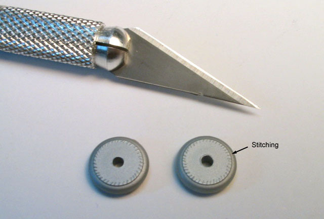
To simulate the stitches around the wheels canvas cap, I
simply took a fresh #11 blade and pressed its tip against the
edge of the kit parts. This is done by free hand, trying to keep
the spacing as even as possible. Then it was just a matter of
crossing my fingers to the effect show up with a careful dark
wash after painting.
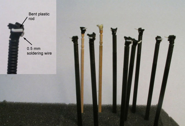
Next, I had to work on the engine cylinders... all nine of
them plus a couple of spares. Basically, I added styrene rods
bent to proper shape in pre-drilled holes to simulate the
exhaust pipes. The same method was used for the intake ducting,
but soldering wire was used instead of styrene.
Another bit added was a pair of handles on each side of the
bottom fuselage, just ahead of the stabilizers. These details
are clearly visible in vintage photos, and were used to handle
the aircraft. I made them from fine brass wire and installed
with white glued in pre-drilled holes.
While the resin copies were curing, I cut 18 little pushrods
from stretched sprue. It is imporant to check the rod diameter
to assure visual consistency and that they will fit the holes
drilled around the cowling.
Click the thumbnails below to view larger images:
Since the kit has no representation of the carburator, a new
one was scratchbuilt from pieces of plastic using the William
Bothers J-5 kit as a reference. A couple of hoses coming from
cylinders 5 and 6 provided hot air to the carburator. They were
made from bulb filament coil with cooper wire inserted inside.
The wire makes the coil remain with the proper shape after
bending.
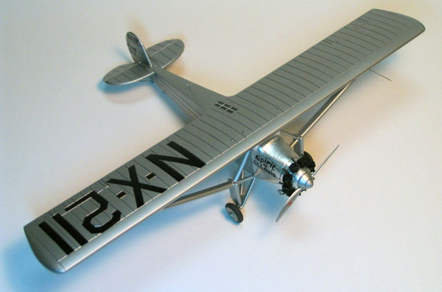
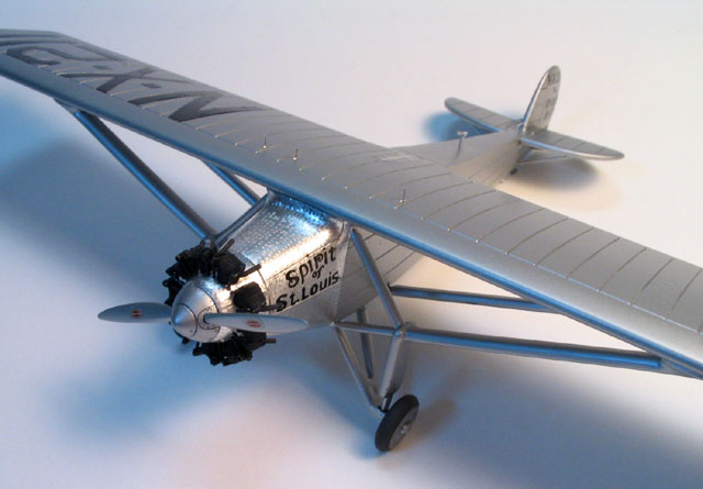
I used Model Master Aluminum Plate buffing metalizer to paint
this model. I mean, ex-buffing. I know many modelers don't like
this product due to its bad adherence. Here is the trick (it
works with all others MM buffable metalizers, too): take a new
bottle of metalizer and leave it open overnight. Because its
solvent is highly volatile, what you will find in the next
morning is a disk of pure metalizer pigment on the bottom of the
bottle. Don't cry... fill the bottle up with 2/3 Model Master
sealer and 1/3 Model Master metalizer thinner. Shake, shake,
shake... The result is an almost-non-buffable metalizer paint
with the same adhesion properties of the MM metalizer sealer.
Now it can be masked like any enamel paint. Same pigment, same
coverage, we just exchanged the paint carrier fluid. On the
other side, it is now much harder to be polished, but during the
experiences I achieved different paneling effects by polishing
the surfaces with SnJ powder or fine glitter.
The resulting finish is a bit different than the original
metalizer, too. In the case of MM Aluminum Plate the recipe
gives a slightly darker aluminum color, but to my eye this is a
perfect match for aluminum doped surfaces... exactly what I was
looking for.
Click the thumbnails below to view larger images:

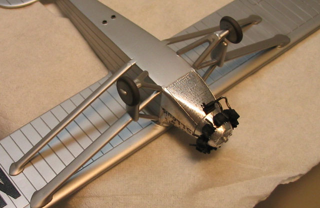
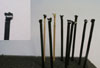
I think the most difficult thing during the painting was to
make the paint hit the upper sides of the main wing struts
without flooding adjacent areas. Using a Badger 100 with fine
tip in one hand and a piece of paper to be used as a barrier in
the other, I spend half an hour applying the aluminum finish to
the whole model. Half of this time was spent trying to cover the
upper surfaces of the wing struts.
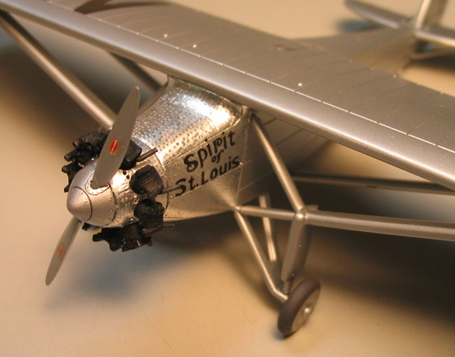
The only non aluminum areas were the engine bits and the
tires. The cylinders and pushrods were painted with Floquil
Engine Black, which is dead flat. Later I brushed the rock
covers and the pushrods with straight Future to make these areas
gloss, producing a distinctive contrast with the finned region.
This effect is very characteristic in vintage radial engines.
The wheel tires were painted with the late Aeromaster Tire Black
enamel. The canvas cover was painted afterwards with the aid of
a drafting template.
Simulating the "Brushed Panels"
|
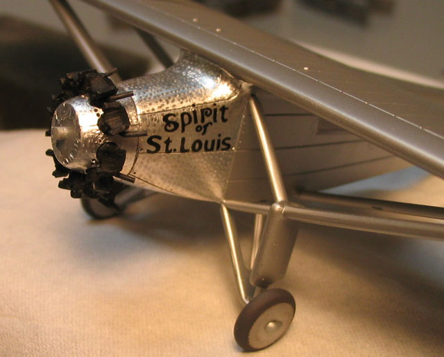
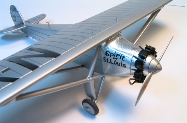
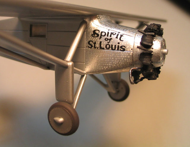
The most challenging step of this project was to replicate
the 'brushed' panels around the nose. The Ryan NYP was in fact a
modification of another Ryan aircraft, where every available
space was used to store fuel, including the nose area. To add
the necessary strength and avoid direct sun light, the
windscreen was removed while the whole nose was paneled. Since
this was a one of a kind aircraft, no steel tool was produced to
forge these curved panels. Instead, they were manufactured by
hand. I still don't know whether the panels were brushed to
force the plates to conform the (wood) patterns or it was just
an aesthetic measure.
It is worth to note that the original Spirit of St. Louis on
display at the Smithsonian Museum currently shows a distinctive
gold hue on these panels. Judging from vintage photos, it was
not this way back in the 20's. This is probably a result of
progressive oxidation of the steel panels. I mention this here
because I found some models of the Spirit of St. Louis with
their nose painted with gold tints. I think this is incorrect
unless you are building an exact replica of the aircraft as
displayed today.
Well, I tried various techniques to replicate the effect on
scrap parts. Too many to list here. After posting for help in
Hyperscale forum, some fellows came to rescue advising me to do
exactly as it was done in the actual machine: to brush the
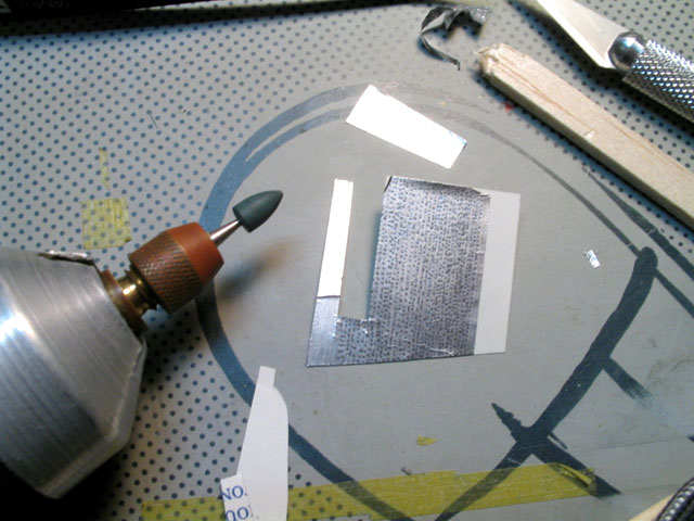
metal. And so I did. The method uses Bare Metal Foil (I used
matte aluminum) brushed with a motor tool. I took a good piece
of Bare Metal Foil and blured small dots all over the area. The
secret is to use an adequate tool to burnish the dots on the
foil before its application. After a few trial and error
attempts, I elected a small conical rubber-type polishing tool
resting for years on the bottom of my accessory case. Sorry, but
all I know about the stuff is I bought it in a dentistry shop
retail, and it is intended for polishing dental prothesis. I
installed it in a slow speed motor tool and painfully burnished
endless rows of marks. Very boring, but all it takes is to keep
the tool perpendicular to the foil sheet, light fingers (just
let the abrasive head touch for a second the foil, then move on
to the next one - never put pressure on it), and patience. I
almost went blind doing this, but thankfully this is a 1/72
model. Given my lack of talent with Bare Metal Foil, I ruined
some sheets during the application and had to go back and make a
few more. The sheets were applied by panel using the standard
method: cut oversized, trim the excess (use the panel lines as a
guide) and move to the next panel. The only deviation was the
top panel of the cowling, which has a double curvature area
around the wing leading edge. In that case I applied two stripes
of foil to make the job easier, then retouched the brushed marks
with the motor tool along the joint line. You can't tell where
the joint is...
After foiling the whole nose, I burnished the scribed panel
lines with a piece of dampened balsa wood. A light wash of
black/brown was applied before the installation of the cylinders
to highlight the panel lines and rivets. Once I was satisfied,
the cylinders were individually pressed into their holes with
white glue. Tragedy almost struck when I realized the during the
pushing some panels slid a bit from their location. I carefully
removed the cylinders, slid back the offending panels and
started over, this time tearing off as much as possible of the
foil from the holes. Alignment is critical here. I'm still
unsatisfied with the position of some cylinders...
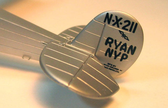
The decals were all applied before the installation of the
smaller details. I was very concerned about how invisible
would be the kit's Invisa-Clear decal film on the rudder,
since I planned no top clear coat. In addition, the brushed
marks on the cowling could be a potential source of silvering.
In the end the result was very good, with no silvering
at all. I don't know what is your experience with Invisa-Clear
decals, but I guess that my old indian recipe for the
metalizer helped to avoid problems. On de other hand, I found
all fuselage decals a bit oversized to fit properly between
the panel lines.
The carburettor was then installed. I had to reinstall a
couple of misaligned cylinders. Then the tail skid, the wheels
and their tear-drop axle covers were glued in place.
Next, all pushrods were individually glued in place using
white glue. At this point I test fitted the propeller and
retouched some of the engine areas with Future, as
mentioned above. As a final touch, rust colored pastel
chalk was lightly rubbed around the end of each exhaust
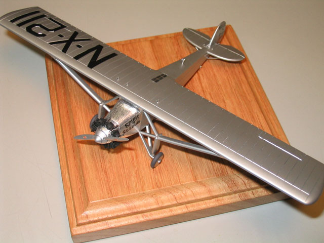
pipe. The N-X-211 code letters were applied on the top and
bottom of the wing. At the beginning of this project, I
decided not to fill the decal placement recesses for the
wing decals to avoid rescribing the ribs. I still regret
the decision, as the recesses are very visible. To avoid
further problems I trimmed off any clear film from the
wing decals, only to discover that they don't match
perfectly the corresponding recesses. Still passable,
though. The spinner received a black wash to highlight the
rivets and other scribed details. The propeller blades
received logos stolen from another kit. Almost there...
Click the thumbnails below to view larger images:
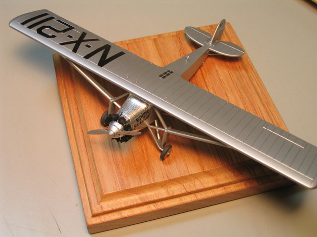
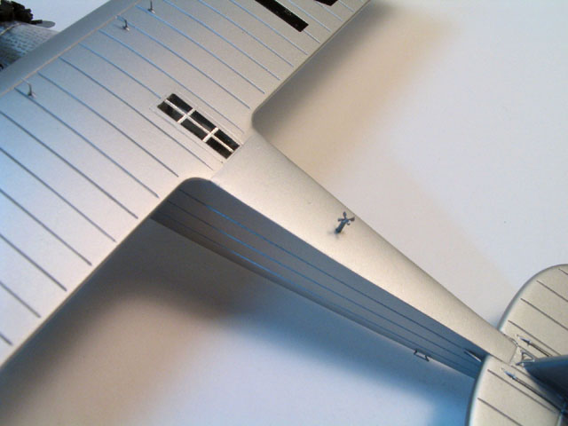
The frames of the cockpit's ceiling window are thin
stripes of Bare Metal Foil carefully pressed in place. The
three fuel tank vents on the top of the wing are L-shaped
stretched sprue installed in tiny pre-drilled holes. I
photoetched a set of very small blades for the wind driven
generator, glued them at the end of a styrene rod,
painted, and installed it on the fuselage spine. The last
detail added was a stretched sprue pitot tube. The
weathering was limited to a light wash on the wheel
covers, cowling and spinner.
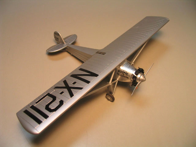
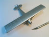
And that's it. The engine/nose area resulted in a lot
of work, but careful planning saved me a lot of trouble.
In retrospect, I should fill the decal markings on the
wing. Apart from that, I'm very satisfied with the result
considering the kit used. I can't wait to see it displayed
side by side with the J-5 engine. It was an enjoyable
deviation from guns, bombs, and swastikas... but at least
I now have a decent model of a historically very
significant aircraft.
... and of course, my thanks to many HyperScalers and
HotWashers for the help.
 Home |
What's New |
Features |
Gallery |
Reviews |
Reference |
Forum |
Search
Home |
What's New |
Features |
Gallery |
Reviews |
Reference |
Forum |
Search