|
“Cheesebox on a
Raft”
Union Ironclad USS Monitor
by Charles Landrum
|
|
|
Union Ironclad USS
Monitor |

Battle Axe's
1/144 scale Ironclad USS Monitor is available online from Squadron.com
In the United States, the epic struggle of the
American Civil War continues to fascinate and even invoke visceral
reactions 140 years after its conclusion. While the other naval actions of
the war have faded with time, the “duel between the ironclads” USS
Monitor and CSS Virginia is ingrained in the historical
conscience of the nation. (It is often more commonly known as the “Monitor
and the Merrimac”, because Virginia was rebuilt from the
scuttled steam frigate USS Merrimac).
The Monitor was a technological marvel in a
time when navies still relied on sail and broadside guns. Her designer,
John Ericsson an eccentric genius of Swedish birth, was both hailed and
derided by the Navy and the public. To many the radical USS Monitor
was going to be the savior that would turn the tide of misfortune suffered
by the Federal Government to that point. She came into being to defeat the
monster ironclad the Confederacy was building to lift the Union naval
blockade of it’s waters; it was to be a contest of David versus Goliath.
Despite this popular acclaim, Monitor was derisively referred to as
a “cheese box on a raft” by many skeptics.
So the historical stage was set when Virginia
sailed out on March 9th to finish the ravaging of the Federal
fleet that she began the day before. USS Congress was still burning
and only the masts of the USS Cumberland remained above water,
when Virginia came out for round two. In the morning light, the
crew of Virginia saw a low form silhouetted in front of USS
Minnesota, their next intended victim. They soon realized that the
vessel that looked like a water tender was in fact the much-rumored Union
ironclad. The ensuing engagement consumed the daylight hours with neither
opponent really gaining the upper hand. Monitor was less armed but
more maneuverable, while heavily armed Virginia sluggishly sought
advantage. It was a tactical draw.
Virginia sailed back up the Elizabeth River to
Portsmouth never to threaten the blockade again, leaving the Hampton
Roadstead in Union hands and the James River the only
Confederate-contested waterway in Virginia. It was on this river that
Monitor spent her remaining operational months, protecting the flanks
of General McClellan’s ill-executed campaign to Richmond. Monitor
was lost later that year on December 31st, 1862 to a fierce
storm off Cape Hatteras, North Carolina. She had been in tow to
Charleston, South Carolina for the impending naval siege of the birthplace
of the rebellion.
Last year, the US Navy and the National Oceanic and
Atmospheric Organization raised the turret of USS Monitor 140 years
after her loss, culminating a 25-year recovery effort. The numerous
artifacts recovered from Monitor are being conserved at their
permanent home in the Mariners Museum in Newport News, Virginia. It is
perhaps no coincidence that Battle-Axe chose this time to release a new
kit of this important ship.
References:
-
Miller, LT Edward M.,
U.S.S. Monitor: the Ship that Launched a Modern Navy. Leeward
Publications Inc., Annapolis, MD. 1978.
-
Tucker, Spencer, Arming
the Fleet: U.S. Navy Ordnance in the Muzzle Loading Era. Naval
Institute Press, Annapolis, MD. 1989.
-
Besse, Summer B., C.S.
Ironclad Virginia and U.S. Ironclad Monitor, Mariners Museum, Newport
News. 1937 (reprint, 1978).
Battle Axe's
1/144 Scale USS Monitor
|
Out of the box, the 1/144 scale Battle Axe kit of
USS Monitor depicts Monitor’s stripped-down-to-fighting-trim
configuration at the time of her duel with Virginia. For the
engagement Monitor was ballasted low in the water, her intake and
exhausts stacks removed and stowed, as were her staffs and davits. She was
configured as Ericsson intended, offering the smallest possible target.
However, this makes for a rather plain ship model.
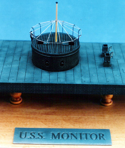
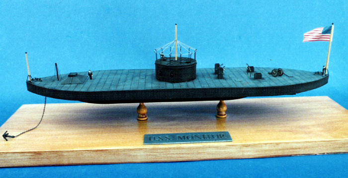
My build-up of the Battle Axe kit depicts Monitor
as she was outfitted for James River duty, June 1862. I chose this
configuration because it typifies the blockade duties the Monitor
and subsequent classes of monitors were primarily engaged in, and offers
more visual interest.
This configuration required the following additions
to the kit:
-
Sloped armor around the
pilothouse; added after the battle with Virginia to reduce the
proven vulnerability of this critical station.
-
Intake and exhaust stacks
-
Flag staff, jack staff,
turret staff and signal pole
-
Davits
-
Awning stanchions and
rigging on the turret
I chose to leave off the deck-edge stanchions and
lifeline and the turret lifeline, for these were seldom rigged on blockade
duty. I also left off the awning for better viewing inside the turret.
The kit is a fairly accurate representation of the
ship and is not hard to build despite initial appearances. The model
compares favorably to available drawings and references and captures a lot
of subtle detail overlooked in other kits. The accuracy of the turret is
the principal weakness of the kit. The one sheet instructions were for the
most part clear and provided scale drawings in scrap views of the more
complex assemblies. The slightly rough surface molding of the low
injection molding process is an advantage in replicating the cast iron
plate of the ship. The kit comes with an accurate 34 star flag and a small
photo-etch fret, which includes the ladder for the turret exterior and an
anchor chain. The nameplate is nicely molded in styrene.
The breakdown of the parts works well. The deck is
molded as once piece, as is the hull, so there are no large seams to deal
with. With that said, the kit does suffer from heavy sprue attachments and
large injector pins. Fortunately the injector pin marks/residue are not
visible but they do interfere with the fitting of components.
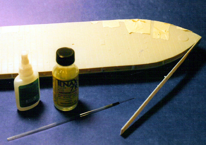
The Hull
I started the kit with the “raft”, adding the wells
that get sandwiched between the hull and the deck. Battle Axe got the
shape of the propeller well right based on my interpretation of the
available drawings; it fit with minor sanding. In assembling the two
halves of the anchor well, I found that it was slightly oblong in shape,
so I replaced it with a styrene cylinder from my spares box. I drilled a
.06 hawse pipe, 3/32” down from the top of the well and added a fairlead
shaft of .047 styrene rod across the diameter of the well at the same
level as the hawse pipe.
Next I fitted the supports for the deck, which
required considerable action with my sprue cutter to remove the forest of
injector pins. Only two supports “beams” are provided to set the spacing
between the deck and lower hull. While this may be adequate, I erred on
the side of caution and added additional supports fashioned out of .04
styrene. There was no easy way to make the alignment between the hull and
the deck, so I eyeballed it in with a steel rule as a straight edge,
checking alignment at various points along the edge!
The anchor well lines up with its cover plate, but
the rectangular access cover to the propeller well does not. The location
of the access plate is too far aft based on the drawings, so I shaved the
old one off and fashioned a replacement from .02-inch styrene and
relocated it slightly forward. Once the raft assembly was dry, I turned it
up on end and sanded all edges even with 150-grit sandpaper taped to my
bench top. This had the added benefit of chamfering the ends of the
supports beams to match the curvature the hull.
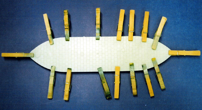
Adding the side plate was easier than I believed it
would be. The side armor comes in four strips, two per side, with a
designed overlap. I eliminate this overlap piece when I discovered that it
was not sufficiently deep to accommodate the thickness of the overlapping
section. Instead I sanded it for a tight butt joint. The side plate does
need to be chamfered at the end to achieve a point at the bow and stern
joints. I used CA to fix the plate at the bow and worked aft attaching it
with liquid cement.
The alignment along the deck edge and hull was good.
I used tape to keep it from springing out. Using liquid cement to make the
butt joint, I proceeded aft with the second piece. I ended up only
trimming of 1/8” of side plate at the stern and then chamfered it as well
for a good joint. I repeated the process on the other side.
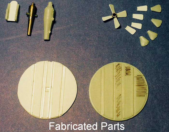
The Monitor’s propeller and rudder, protected by a
skeg, was an ingenious design for a vessel whose intended use was in the
shallow waters of the coastal estuaries of the Eastern seaboard. The kit
captures this design well. However, the individual blades of the propeller
are overly thick. In addition, the propeller hub molded to the end of the
roughly cast shaft is too rough. I opted to make a new, more realistic
propeller from scratch from styrene. The blades on Monitor’s propeller
were variable pitch - that is each blade has a helical twist from the hub
to the tip. Even though Battle Axe captured this variable pitch in their
overly thick blades, I felt that thinner blades with a fixed pitch would
be more realistic in appearance. If I had made the blades from brass, I
could have varied the pitch, but I opted for the less time-consuming
styrene solution. I made the new propeller hub from .25-inch brass tube
cut to a length of 6/32. The blades were shaped made from .02 X .250
styrene strip. These were then glued to the hub at the proper angle using
CA. I made the propeller shaft from .100-styrene rod.
Assembling the skeg assembly required only clean up
work. I drilled a hole for the shaft and then glued the Y-shaped shaft
support to the hull. Then it was just a matter of sliding the shaft
through the propeller hub and shaft support. I used CA to secure the
propeller and liquid cement to secure the shaft. There was no problem
fitting the rudder, which I left centerlined.
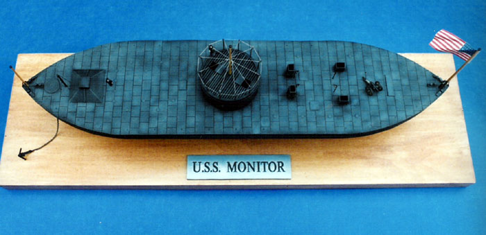
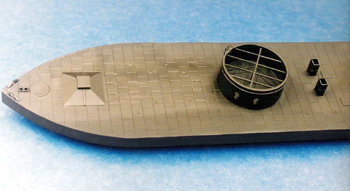
Topside
With the hull together, I concentrated on adding the
deck details. As is typical with most kits these days, the instructions do
not identify the components of the subject. So I wanted to take a moment
to identify the molded features of the deck. Between the stacks are two
hatches, which were the access hatches to the coalbunkers. The raised
round bumps on deck, represent the thick glass prisms that admitted
daylight below decks. The deck edge stanchion sockets are represented by a
series of evenly spaced dimples. These subtle features are why this kit is
the most accurate available.
I used the kit bollards and open chocks, though the
open chocks required a lot of cleanup and were a bit fragile to work. I
assembled the pilothouse per the instructions and then glued it in place
as well. It required a lot of cleanup to get plumb.
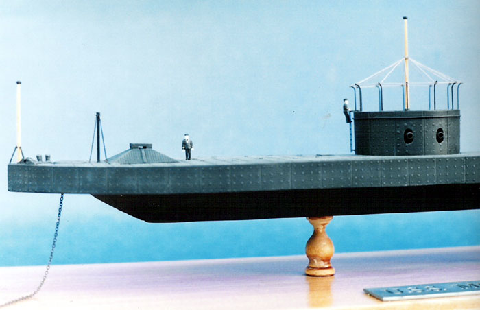
As I mentioned earlier, the pilothouse was found to
be too vulnerable in combat and additional armor protection was added.
(This forward location of the pilothouse proved impractical and all
subsequent classes of monitors located the pilothouse on top of the turret
to provide greater protection and ease communications.) I replicated this
armor, made from T-bar, by using .04-inch spacing, .02-inch thick V-groove
siding. I cut four sections using enlarged drawings from the Leeward Press
publication as a template. I chamfered the sides for better fit and
started with the forward piece. I used liquid cement to glue it just below
the view slits. I then fitted and secured the sides and finally fitted and
secured the aft piece. The side armor also received prototypical
reinforcement strips made from styrene strip.
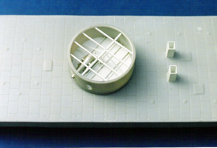
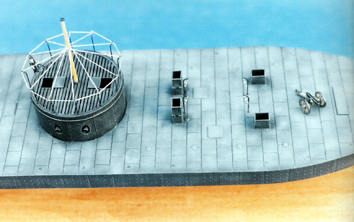
Next came the stacks. On the Monitor, these were
removable and I believe came apart in sections for storage below. The
forward two were the exhaust stacks and the aft two the intakes. For some
reason, Battleaxe chose not to include the stacks, although they provide
the deck-level grills. It was an easy matter to make stacks from
.02-styrene strip. I built them up in place and added small details from
scrap styrene. Adjacent to the stack were four J-bar davits, their
locations being molded into the deck. I made four, .5-inches tall from
brass wire. I attached spare PE blocks and tackles in a stowed position.
Finally the signal pole forward of the pilothouse was made from styrene
rod and the stays rigged with fine brass wire.
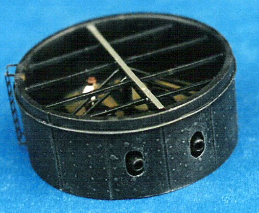
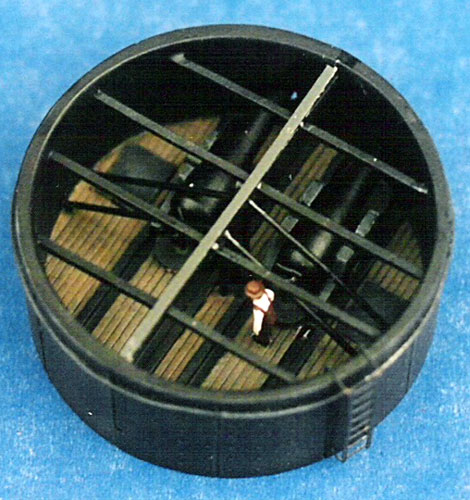
The
Turret
Built straight from the box the turret is a passable
replica. What is provided is a floor plate and roof plate, both with
recessed lines, and side plating with bolt head detail. The turret sides
are molded in three sections, which I initially thought odd. But during
assembly found this breakdown to be a clever way to avoid an oblong
cross-section, which two halves might create. In the course of my research
I found that the turret is a less than a correct representation.
The root problem with the kit’s turret is the fact
that the guns provided are too large. What Battle Axe provides are guns
that scale out to be 15-inch Dahlgren smoothbores found in later classes
of monitors. This is somewhat understandable given the fact that there are
readily available drawings of these later turrets. Monitor, however
carried the largest gun then available, which was an 11-inch smooth bore.
There is quite a difference in size in 1/144 scale. The overly large guns
throw off the dimensions of not only the turret floor, but the gun ports
in the turret as well. The correction is involved and time consuming. I
opted to fix the turret and to detail the interior, although it would be
mostly hidden. Also, as a compromise to the molding process, Battle Axe
provides a solid turret roof with engraved lines to represent the spacing
between the inverted railroad rails that formed this roof. In this scale,
the viewer should be able to see into the turret, so I opted to correct
this flaw as well.
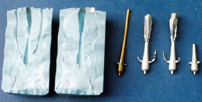
First things first, I needed scale 11-inch Dahlgren
guns. Armed with the book Naval Ordnance in the Muzzle Loading Era,
I found dimensioned period drawings of an 11-inch gun. I looked at
mail-ordering the guns from Blue Jackets, which carries Dahlgren cannons
in their line of ship fittings, but I was unsure if the dimensions would
match. A friend, who is a pattern maker, offered his assistance. With a
copier, I was able to create a reduce-scale drawing from which he turned a
scale barrel from brass. He made a silicon rubber mold and poured
beautiful castings out of white metal.
Armed with properly scaled barrels, I then had a
reference to scale the rest of the work in the turret. I made narrower gun
carriages using the kit provided gun carriage sides a new carriage floor
from fabricated from .02x.250 styrene strip. The carriage then became the
benchmark for the rest of the dimensions in the turret. Using the kit
floor as a circular template and Stevens Institute drawings of the
Monitor found in the Leeward Press book for reference, I scratch built
a new floor from styrene sheet and strip. Leaving space for the track, I
made the floorboards from .04-inch spacing v-groove styrene. Unlike the
kit part, the planking of the turret floor ran parallel to the gun tracks
(If you use the kit provided turret roof this error is hidden and not
worth correcting.) With the floor done, I fitted the sides of the turret.
At this point the instructions are unclear as to which end of the turret
facing is up! The floor should be raised, so the recess partially up the
inside face of turret is for the floor; he recess even with one edge is
for the roof. I filled the gun ports with styrene and CA and re-bored them
with a pin-vise to better align with the new guns and carriages. Of note,
the gun ports on Monitor were formed from three overlapping holes
bored through the armor. In the haste to get the ship to sea, the
scalloped edge was not ground smooth. Try as could, I was unable to
duplicate this appearance!
 The
next step was to detail the inside of the turret. With this work done, I
painted the turret interior with a base coat of flat black. I hand painted
the deck with dark tan and when it was dry, gave it a black wash. I also
spray painted the gun carriages and barrels flat black. The carriages were
dry brushed with Euro 1 gray but the barrels were not. The guns were then
carefully inserted into the turret. The
next step was to detail the inside of the turret. With this work done, I
painted the turret interior with a base coat of flat black. I hand painted
the deck with dark tan and when it was dry, gave it a black wash. I also
spray painted the gun carriages and barrels flat black. The carriages were
dry brushed with Euro 1 gray but the barrels were not. The guns were then
carefully inserted into the turret.
I fabricated gun stoppers, a pendulum of iron plate,
as well and rigged them with PE blocks (pulleys) and tackle inside the
front facing of the turret, rigged clear of the gun ports. I made the
turret roof with Plastruct t-bar stock to represent the railroad rail that
was actually used. I set the spacing with the thickness of a steel
machinists rule. I left openings on either side for the sliding hatches,
which I made from .02-inch styrene . To avoid overspray through the slats,
I hand painted the bars.
Click the
thumbnails below to view larger images:
The last task was to add the turret exterior details.
The PE ladder provided in the kit was bent and installed. Fine brass bead
wire was used to make the tie down ring around the circumference of the
turret. Stiffer brass wire was used to make the awning stanchions at the
top of the turret. These were set into predrilled holes.
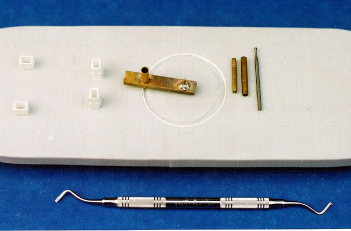
Once I had the basic ship done, there was one detail
that troubled me. The turret in the kit sits on the surface of the deck.
On the Monitor, the turret rested on a recessed brass track. I
wanted that recessed look! So after much angst and with technical
assistance from my pattern maker, I fabricated a jig from brass to allow
me to cut a circular track for the turret. This was not a process for the
faint of heart, but I was committed (or should have been!) The jig was set
up for use with my Dremel motor-tool with a small cutting head. Despite
the softness of the plastic I was able to achieve a reasonable track. I
cleaned up the race with a dental scraper and then ensured a tight fit
with a piece of styrene strip glued along the outer wall. Voila, I had the
look I wanted with only the addition of a few more gray hairs!
Here was an area that demanded a lot of research.
What color was the Monitor? My preconceived notion was black based
on the photos and models I had seen. But there is an undercurrent of
discussion on the web that suggests dark grey. Careful study of available
photos in comparison to the officers and crew on deck led me back to
black. Plus most of the machinery from the period was black. So black it
was. But then that raised the question of the underwater hull. Profiles I
have seen show a red anti-fouling, but I could find no written proof.
Besides If this was indeed the first iron warship, who would of thought of
anti-fouling paint? Plus Monitor was so rushed to get to sea, there was
not the luxury of time, so I opted to keep the ship black from the keel
up. But to give the ship some visual interest I decided to fade the deck
as surely it had been from the Virginia sun.
I painted the model with a base coat of Model Master
Interior Black enamel.
I then used Model Master European 1 Gray to fade the
deck plates. At this point I realized that the deck plate recessed detail
stopped short of the gunwale due to the side armor. I elected to continue
these lines to the edge by scribing with a razor saw. Happy with the
result, I gave the deck plate joint a wash of flat black. To even out the
appearance of the deck plates and the to highlight the small details I dry
brushed the entire model with Euro 1 Gray. In particular this technique
helped emphasize the rivet detail of the hull and turret, the sloped armor
of the pilothouse and the rail spacing on the turret roof. A finish coat
of Testor’s flat lacquer gave the model a uniform, muted look.
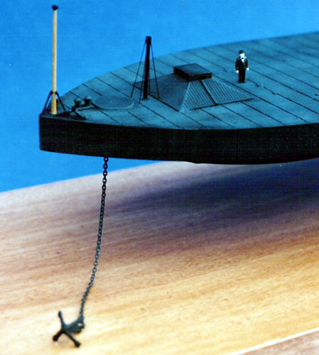
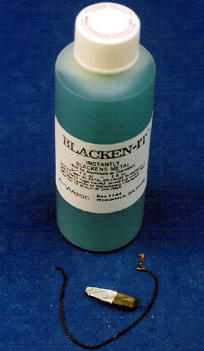 For
the anchor and chain, I used the kit anchor and chain from cosmetic
jewelry, bought in a discount store. It was then dipped in Blacken-it for
a more scale appearance. I carefully threaded and glued it into the hawse
pipe and then connected the anchor with a link made from brass wire. For
the anchor and chain, I used the kit anchor and chain from cosmetic
jewelry, bought in a discount store. It was then dipped in Blacken-it for
a more scale appearance. I carefully threaded and glued it into the hawse
pipe and then connected the anchor with a link made from brass wire.
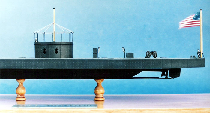
The deck gun was typical of the period. Ships on the
blockade, especially the monitors, often carried a smoothbore howitzer on
a three-wheeled iron carriage to quickly respond to skirmishers and
snipers. It obviated the need to power up and man the large turret. The
cannon is a 10mm scale Napoleon smoothbore field carriage made by Starfort
Models in the UK. It is exquisitely molded in white metal as are the three
Union artillerymen that come with it. The crew figures are N-scale model
railroad figures by Model Power, repainted in period naval uniforms. I
added them to convey a sense of scale of the sheer bulk of the vessel.
The staffs and poles of Monitor required a
traditional ship modeling approach. Styrene rod, although suitable for the
small signal pole, lacks stiffness worked to create a suitable taper. So I
made the staffs by chucking 1/8inch birch dowel into my Dremel and sanding
a tapered into the dowel. The wood was sealed with a one step light stain
and polyurethane. Once stepped into position, I fabricated supports from
brass wire and rigged the awning with from brown polyester thread.
The base I am not happy with, but it will do until I
make a new one. The wood is birch and did not take the finish evenly,
which may be a more of a function of my wood working skills than the
suitability of the wood! I used the beautifully molded kit nameplate for
the base. It was sprayed with Model Master Anodized metal Metalizer for a
machined look and washed with Model Master flat black acrylic to highlight
the letters. I think it makes an appropriate industrial presentation.
As the last act, I raised the ensign!
I substituted the kit flag with a larger one from
Model Shipways. I tried to shape the flag to give it a more realistic
appearance. Leaving a white “fabric” border, I attached it to the halyards
by folding over the paper and gluing it with white glue. The halyard is
white silk thread.
Overall, this Battle Axe kit was an enjoyable build.
Despite the kit limitations, it is the most accurate model of Monitor
available and has potential for a lot of configuration modifications.
Though not designed as a waterline kit, it would make an interesting
waterline display, perhaps with a longboat rowing out. I recommend it for
anyone interested in this period of naval history. Far from graceful, the
Monitor was rugged, utilitarian and business-like in appearance,
not unlike the early tanks that would come 50 years later. In this regard
Battle Axe captures the ship perfectly.
Thanks to
Squadron for the review sample
Charles Landrum is a defense consultant now retired from the US Navy. A US
Naval Academy Graduate, he spent the bulk of his 20-year naval career at
sea serving on six ships of the Atlantic Fleet including USS SAIPAN, USS
ENTERPRISE, USS BIDDLE, USS HAYLER, USS HARRY E. YARNELL and USS KIDD. He
also accumulated time and experience on the ships of the NATO navies,
especially Canadian. An avid modeler and Hyperscaler, he concentrates his
modeling efforts on the ships and aircraft of the US Navy. He and his
family continue to reside in Norfolk
Click on the thumbnails
below to view larger images:
Model, Images and Text Copyright © 2003
by Charles Landrum
Page Created 22 October, 2003
Last Updated
17 March, 2004
Back to
HyperScale Main Page |
 Home |
What's New |
Features |
Gallery |
Reviews |
Reference |
Forum |
Search
Home |
What's New |
Features |
Gallery |
Reviews |
Reference |
Forum |
Search