British aircraft manufacturer Westland made its reputation during the
1920s with a biplane bomber, the Waipiti. Its second successful design was
the Lysander, an army co-operation aircraft..
The Whirlwind was therefore a dramatic departure from Westland's rather
staid history.
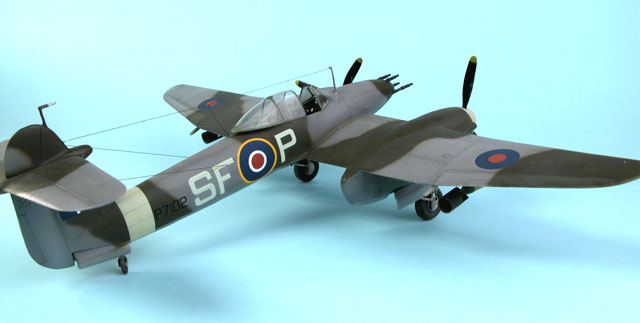
The Whirlwind was the RAF's first twin-engined fighter. It was the
fastest production aircraft of its day at low altitude, and the most
powerfully armed with four 20mm cannon. Its weakness was the Rolls Royce
Peregrine powerplant. This engine performed poorly at high altitude and
suffered from many teething problems.
The development of the Rolls-Royce Merlin engine and the emerging
importance of a new fighter design complicated these issues. Production
was now firmly focused on the Spitfire.
The fate of the Whirlwind was effectively sealed even as it was
entering Squadron service. Instead of fulfilling the thoroughbred fighter
role for which it had been designed, the Whirlwind found itself limited to
ground-attack duties with two RAF Squadrons.
Only 114 Whirlwinds were built. The "Whirlybomber" performed well in
its unanticipated ground attack role until replaced by Typhoons in 1943.
This is not the first Whirlwind in 1/48 scale.
Cooper Details released a beautiful vacform, brass, white metal and
resin kit in the mid 1990s. I bought this kit when it was first released.
Only fear of vacform has delayed the project.
Classic Airframes has also chosen a multi-media path. Injected styrene
now replace the vacformed sheets. Sprue gates are impressively narrow for
a limited run kit. The surface texture is shiny but this belies the
slightly soft nature of the light grey plastic. It is very pleasant to
work with.
Detail is finely engraved where appropriate, with raised ribs on the
wing fuel tanks very nicely done.
The resin and white metal will look familiar to modellers who already
have the Cooper Details Whirlwind. These have been sourced from Coopers
original patterns (with Roy's approval) and are 90% identical to the donor
kit.
The resin parts make up most of the cockpit, the spinners, cannon
barrels, bombracks and unweighted wheels. Small resin parts are cast on a
fine wafer of waste resin. I found that these parts were more difficult to
clean-up than the Coopers resin. Must be a different resin formula.
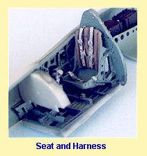
A small photo-etched fret supplies a thirteen-piece Sutton Harness,
rear cockpit shelf, small handles, leading edge radiator faces and a
footstep.
Two vac-formed canopies are included. These are not quite up to Falcon
standards, but they are pretty good.
The double-sided instruction sheet describes the construction in
thirteen illustrated steps. Curiously, one side of my instructions was
printed upside-down! A colour painting guide is also included.
Microscale provide two decal options covering the two common Whirlwind
schemes of Dark Earth/Dark Green and "Mixed Grey"/Dark Green.
The kit is very complete straight from the box, but Classic Airframes
have somehow forgotten to provide rudder pedals. To their credit, though,
the rudder bar is in place!
I thought I'd need a few hours to clean up, trim and shim the limited
run plastic parts in preparation for assembly. To my pleasant surprise,
this was hardly necessary.
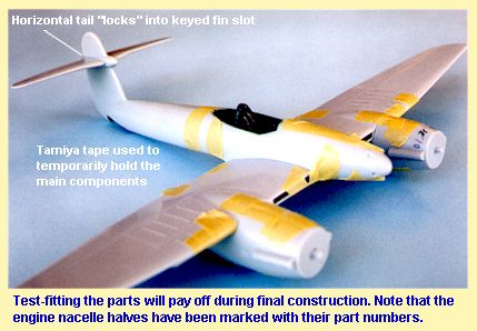
Dry fitting proved that the logic of engineering and quality of fit was
better than many mass-produced kits.
Cockpit and Fuselage
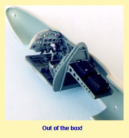 Construction
starts in the front office - and what a front office it is! It is one of
the most completely detailed cockpits straight from the box that I've ever
seen.
Construction
starts in the front office - and what a front office it is! It is one of
the most completely detailed cockpits straight from the box that I've ever
seen.
When preparing the resin parts be careful not to cut through the base
of the seat when removing the casting block. I did!
The resin seat mounts (parts 16 and 17) are very delicate. Great care
is required when cleaning up and attaching these parts.
Once the brass and resin detail parts were added, the cockpit
components were painted.
Now for the cockpit final assembly. There is no positive locating
position for the sidewalls on the inside of the fuselage, so I glued the
instrument panel to the appropriate spot on the starboard fuselage half as
a reference point. I then test-fitted and superglued the starboard
sidewall. The fuselage halves were taped together to permit dry-fitting of
the port sidewall and rear cockpit bulkhead/seat/battery tray
subassemblies. I had to trim a little from the back of the sidewalls to
get a perfect fit. When I was satisfied that everything was square, I
"tacked" the rear bulkhead to the starboard fuselage
 with
superglue, secured the port sidewall, then separated the fuselage halves.
with
superglue, secured the port sidewall, then separated the fuselage halves.
Part 69 (the tail wheel well forward bulkhead) was glued to the
port-side of the tailwheel bay. This part needed trimming to allow the
fuselage halves to meet at the tail.
Despite the lack of locating pins along the fuselage, the cockpit and
tailwheel bulkheads provided a positive fit for the fuselage halves. The
cockpit floor was added from underneath when the fuselage halves were dry.
I did lose a couple of the tiny cockpit brass parts during
construction. Don’t feel too bad is this happens to you too - the cockpit
still looks great!
Wings and Tailplanes
 There is
really not much to say about the rest of the construction. Dry-fitting is
once again the first and last rule, particularly as there are no locating
pins.
There is
really not much to say about the rest of the construction. Dry-fitting is
once again the first and last rule, particularly as there are no locating
pins.
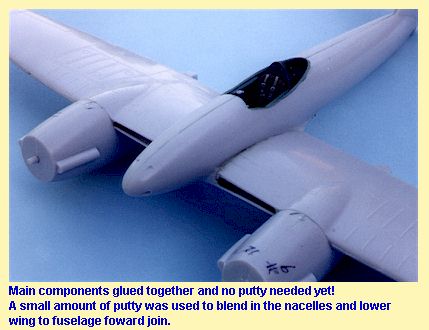
The wing comprises a lower centre section, separate outer lower
sections and a port and starboard upper surface. This clever engineering
means that the correct dihedral on the outer wing panels is set. I needed
to trim the leading edge of the lower wing (starboard side) where it meets
the lower fuselage. This ensured a tight, step-free join at the wing root.
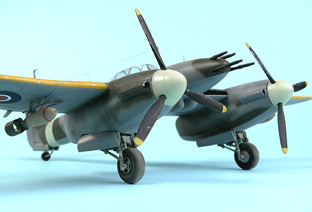
Engine nacelles include styrene bulkheads fore and aft. This area could
do with some extra detailing for the truly compulsive modeller. I drilled
out and thinned the front of the exhaust dampers.
The single-piece horizontal tail surfaces are represented with a slight
"gull" effect. For the life of me I couldn't find reference to confirm if
the gull effect was up or inverse - or even if it was really present! To
make matters worse, the part fitted pretty well either way. The part is
cleverly designed to lock into a "key" slot in the vertical tail.
Finishing Off
 I
flattened the resin wheels slightly and assembled the main undercarriage
legs. Each main undercarriage assembly comprises two halves between which
the mainwheel is trapped. The width imposed by the arch is way too wide. I
trimmed and dry fitted the white metal arch until the wheel fit snugly.
I
flattened the resin wheels slightly and assembled the main undercarriage
legs. Each main undercarriage assembly comprises two halves between which
the mainwheel is trapped. The width imposed by the arch is way too wide. I
trimmed and dry fitted the white metal arch until the wheel fit snugly.
The white metal undercarriage locates either side of two lugs on the
forward nacelle bulkhead. I had to thin the front of the wheel well
opening to get sufficient clearance for the top of the legs. The
retraction struts rest on a ridge moulded onto the aft nacelle bulkhead.
The white metal can be easily adjusted to fit this ridge.
Undercarriage doors will need some help to attach to the nacelles. I
superglued two short lengths of brass wire to each main door. These acted
as "hinges", which could then be glued to the inside of the nacelles. The
process was repeated for the tailwheel doors.
The 20mm cannon require big holes in the nose. I used a 1/10"
drill to accommodate the resin guns. I used the same drill to deepen the
locating holes for the prop blades.
The kit instructions suggest that parts PE 19 and PE 5 are optional. In
my opinion they are not. These parts are installed at the rear of the
vacform canopy. They are prominently visible through the big bubble
canopy, and furthermore are required to correctly angle the canopy if it
is to be positioned open.
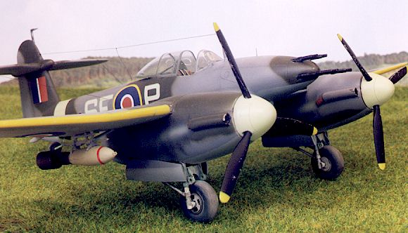
I substituted Coopers' metal bombracks for the kit resin parts, and
used 20 thou styrene rod as braces. Bombs are not supplied in the kit so I
used the 500lb bombs from MDC's "British Full Weapons Load" set. These
bombs are lovely little models in their own right, with resin bodies,
photo-etched fins, fusing props and nose ring and a white metal tail ring.
I broke off the pitot tube and antenna mast about five times during
construction and painting. I'd recommend drilling locating holes during
construction, but leaving them off until you've almost finished painting.
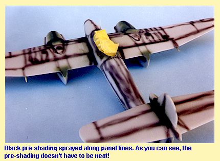 I
started off by spraying the yellow leading edges and the sky fuselage
band. These were masked off and then black was sprayed along panel lines
as a pre-shading coat. This is designed to slightly show through the grey
colour.
I
started off by spraying the yellow leading edges and the sky fuselage
band. These were masked off and then black was sprayed along panel lines
as a pre-shading coat. This is designed to slightly show through the grey
colour.
Next step was to spray the Medium Sea Grey lower surfaces. I used Gunze
H335 lightened with a little Gunze RLM 76.
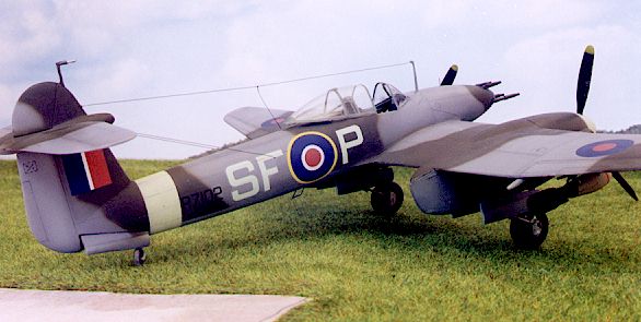
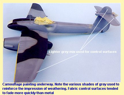
More masking now - this time the upper-lower demarcation line to get a
nice sharp division between the colours. The grey used on Whirlwinds was
the early "mixed grey". This comprised six parts of Medium Sea Grey mixed
with one part Black. The contrast between this colour and the lower
surface was therefor quite low. I used Gunze H75 to represent this colour
(at Chris Wauchop's suggestion).
 There
is a fabulous in-flight colour photo on pages 232-233 of "The Hamlyn
Concise Guide to British Aircraft of World War Two" by David Mondey. I
used this photo as a guide to the colours, the camouflage and the
weathering of my Whirlybomber.
There
is a fabulous in-flight colour photo on pages 232-233 of "The Hamlyn
Concise Guide to British Aircraft of World War Two" by David Mondey. I
used this photo as a guide to the colours, the camouflage and the
weathering of my Whirlybomber.
Gunze H330 Dark Green was applied in a freehand pattern over the "mixed
grey" to complete the camouflage.
The bombs were painted according to another colour photo on page 155 of
the previously mentioned book.
Decals performed extremely well.
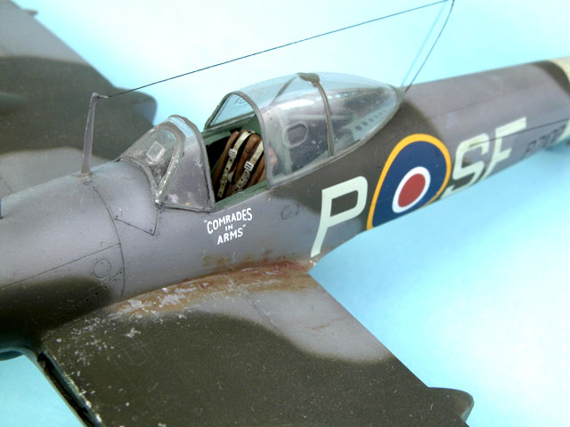
Some light weathering followed. The wing root on the colour photo seems
to be scuffed and showing some of the earlier coat of Dark Earth under the
mixed grey. I made sure that I captured this interesting detail. Chipping
was added to wingwalks, leading edges and prop blades using Tamiya Chrome
Silver Enamel. Panel lines were highlighted with a thin wash of Tamiya
acrylic Semi-Gloss Black.
Gunze Acrylic Flat was used as the topcoat.
Aerial wire rigging is quite prominent on the Whirlwind. I drilled
locating holes for the radio and IFF aerial wires in the fin, fuselage and
leading edges of the horizontal tail using a No. 77 twist drill.
Smoke-coloured monofilament (invisible mending tape) was used for the
aerial wires.
I painted the wingtip lights with white before a topcoat of Gunze Clear
red and Clear Green. Although I know my port from my starboard, I somehow
managed to paint the colours on the wrong wingtips!
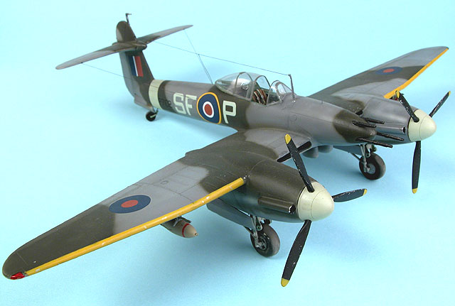
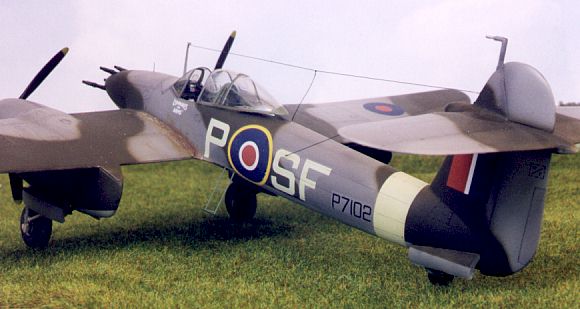
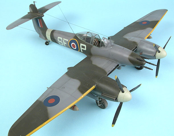
I love the look of the Whirlwind. I particularly like the way the clean
basic lines of the aircraft bristle with cannon barrels, the mast, pitot
tube, aerial wires, bombs and the boarding ladder.
Classic Airframes have created a model that represents this graceful
but purposeful aircraft very well. It is worthy of the wonderful Cooper
kit before it. Having said that, the small parts and extensive use of
multi-media means that Classic Airframes Whirlwind will be best suited to
the experienced modeller.
This kit is fabulously well-detailed out-of-the-box and, with a little
care and plenty of test-fitting, builds up into a very impressive little
Whirlybomber.
Click the
thumbnails below to view larger images:
Text, Images and Model Copyright © 1999 by
Brett Green.
Page Created 29 January, 1999.
Last updated
17 March, 2004.
Back to
HyperScale Main Page
 Home |
What's New |
Features |
Gallery |
Reviews |
Reference |
Forum |
Search
Home |
What's New |
Features |
Gallery |
Reviews |
Reference |
Forum |
Search