|
The 1/72 Scale Contrail
Sutcliffe
North American XB-70
by Bill "C2C" Dye
|
|
|
North American XB-70
|

HyperScale is proudly supported
by Squadron.com
I know what you’re thinking: ‘Why the heck did this guy build this
kit when there’s an injection kit!?’ Well, simple answer: when I built
this monster, the injected kit wasn’t out yet – not for several years.
Over the last 15 to 20 years I’ve built other vacuform kits, e.g. XB-35
Flying Wing, FJ-1 Fury, KA-3D Sky Warrior. It always seemed that within
a few years of me building the vac kit an injection kit would come out.
How many times I would hear at the San Jose or Fremont ,California IPMS
meetings, “Hey Bill, did you hear? . . . someone’s coming out with an
injection kit of the ________” (fill in the blank). It got to the point
that I was getting requests! “Would you build the Rareplanes Aircomet so
I can build it later as an injection kit.” Eshh!
The XB-70, to me, is one of the coolest aircraft ever designed and
flown. To imagine that this huge machine saw around Mach 3 is mind
boggling. I can only imagine a scene like that in the movie, “A
Gathering of Eagles” where all of the B-52s were taking off – except
they're B-70s instead!
This aircraft was once destined as a supersonic replacement of the B-52,
it began a test program in the 60’s with two machines. One had no wing
dihedral and another 5 degrees. With a higher cruise altitude and
supersonic speed the XB-70 was to fly higher than the opposition to its
target(s). Unfortunately missile technology surpassed the XB-70’s
altitude and speed safety area and growing costs led to its demise. The
aircraft seems to be well known by the infamous and fatal crash
involving an F-104 and other aircraft prior to the program cancellation.
I saw the remaining XB-70 at Wright Patterson AFB in 1972 (when it was
outside, I heard that they built the new museum around it!). I had an
“Instamatic” camera and wanted to fill the frame with the airplane and,
of course, my bride (no, I wasn’t on my honeymoon but it was still less
than one year . . . that counts as a bride). I moved farther and farther
away to fill the frame. I moved back and back until I finally got the
entire aircraft in the frame. Later, when I got the photos back from the
drug store, in the photo I saw a pink dot at the base of the nose gear .
. . . my wife wearing a pink blouse. She hates getting her picture taken
so I wasn’t surprised when she said she wished all of my photos of her
would be like that! Critics!
As an aside . . . . .
To digress further: I worked for Rockwell International on the Space
Shuttle from 1973 to 1977. I was a young punk kid working as a wind
tunnel test engineer in the Aerodynamic Heating Wind Tunnel Operations
Group of the Flight Sciences Department in Downey, Calif. I was in model
heaven! I worked on the aerodynamic heating models for ascent and entry
heating. (Oh yea . . . . we weren’t allowed to say re-entry because it
hadn’t left the earth for the first time!. . . . sounds like a ‘Dilbert’
to me.) I was a wind tunnel test engineer and I was responsible for
getting the models designed, built and conduct the tests to collect the
data that the smart (4.0 students) would analyze.
I got to test many
different types and sizes of models in several NASA and Air Force wind
tunnels. I did most of my testing with an OTS model (Orbiter + Tank +
Solid rockets) with the Orbiter about 24 to 30 inches nose to body flap.
I don’t remember the scale. We were quite concerned about the tiles
(obviously) and had to see if a) they would work and b) how precisely
would they have to be installed. We did thin skin thermocouple tests and
phase change paint tests. That’s special white paint applied to a
special black epoxy model - the paint goes clear at a specific
temperature. Take motion pictures of the paint changing ‘phase’ and you
get temp vs. time = heating rates. We did some IR testing a few years
later (newer technology). These models were really cool. The thin skin
thermocouple model was all stainless steel and had about 1,000 T/Cs all
over just the Orbiter with 1,750 T/Cs over the entire OTS configuration.
The Thermocouples were positioned along the top and bottom fuselage
center lines, along various wing cords (left wing top, right wing
bottom) and specific “hot spots” like the windshield and the OMS pods. I
wrote the test plans, told the model mechanics what configuration to set
up (all flying surfaces were adjustable).
It was really cool seeing the Enterprise on roll-out day. I could see
things on the Orbiter that were a direct result of some of the tests I
was responsible for. But this could be a whole ‘nother story.
At the time, there were actually some supervisors and managers that were
looking ahead to the first Shuttle flight with respect to correlating
flight data to wind tunnel data. The top surface of the wing had a
different type of insulation than the tiles since the heating rates were
significantly lower. But they wanted to be sure they had sufficient
margin and so they called a meeting to discuss ideas for getting some
actual flight data from the top surface of the Orbiter wing during the
first entry. This wasn’t a safety issue. It was more: ‘Can we use easier
to maintain insulation to save maintenance costs and turnaround time?’
I, the kid 2 years out of college, sat in a meeting with the Department
Manager, my Supervisor and the Analysis group Supervisor. There was a lot
of discussion about ways to instrument the top surface of the (real)
wing. Well, I went and opened my mouth and said, “Why don’t you put an
Infa-Red (IR) camera in a pod on top of the vertical tail looking down
on the top surfaces of the fuselage and the wings?” Gee, they didn’t
laugh! They actually listened and discussed it for about 10 minutes.
But, it didn’t sound like they were going to do it. So, to promote my
‘great idea’ I said, “Well, you could also put a visual camera up there
too. It would be great for Public Relations. Wow! A shot of the Orbiter
during re (oops, sorry) entry.”
Silence . . . . glares . . . mumbling . . .That did it. The Manager,
standing up while closing his tablet portfolio, said, “No pod with a
camera and Paul (my Supervisor), talk to this kid about this will ya?”
More glares. Meeting over.
Yikes!
Paul pulled me into his office and s’plained to me that, as he put it,
“We never, ever, ever talk about doing something for ‘PR’.”
“Why?” I asked.
“Because,” he said, “several years ago we lost the XB-70 because of
‘PR’.”
“Huh?” I said with ‘duh’ written all over my face.
“They conjured up a ‘mission’ to fly the XB-70 with all of the other
aircraft in the Air Force inventory that used the same engines to get a
publicity photo for the engine manufacturer. They wanted a ‘tight’
formation for a better picture. An F-104 got too close and it got caught
in the wing tip vortices of the XB-70, rolled across it’s back clipping
off the vertical stabilizers. The XB-70, F-104 and another aircraft went
down killing a few of the pilots. It was decreed to never do anything
like that again.”
“ . . . . . . Oh.”
So, I became interested in the plane and read the few books that were
available. Now I not only love the aircraft but I have a memory – albeit a
faux pas.
The 1/72nd Scale
Contrail Sutcliffe XB-70
|
That is one reason anyway why I decided to brave the huge box and build
the b e a s t. Photo 2 shows the box and most of the contents. I kept
checking the scale – then I remembered taking the photo at Wright Pat –
it is very big!
There were drawings for either version. I chose the zero degrees
dihedral and the nose set in the subsonic position. Large, and I mean
large, sheets of plastic for the main parts, metal landing gear struts
and decals.
Construction
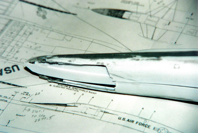
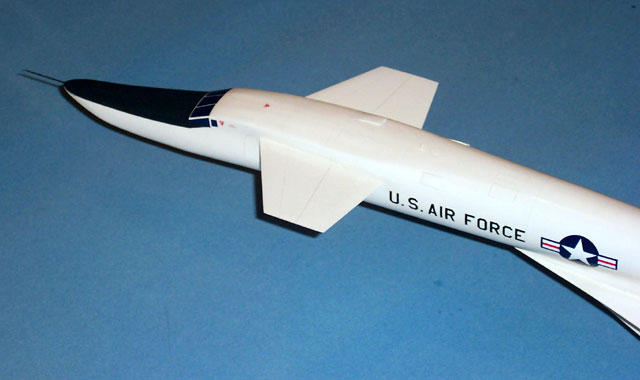
After studying the plans and the various pieces, the nose (or goose
neck) just didn’t look right. Looking head-on, the model looked like a
chipmunk and from the top like a duck. I studied more photos, then the
drawings, then the parts, back and forth and finally decided to make
some “fixes”. I removed the ‘cheek’ and filled with Bondo or putty and
re-contoured each cheek half before removing it from the backing sheet.
There was so much cutting and filling that it was an easy decision to
NOT put in a cockpit (can’t see in the windows in all of the photos
anyway. That’s my story and I’m sticking to it!
Click the thumbnails below
to view larger images:
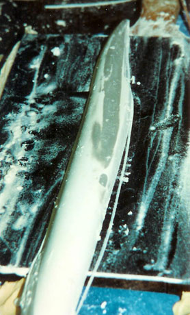
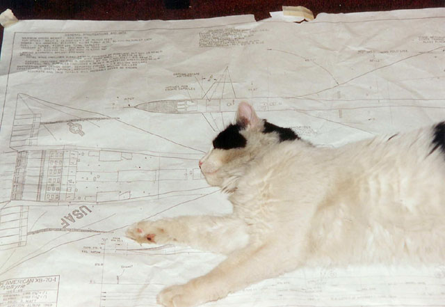
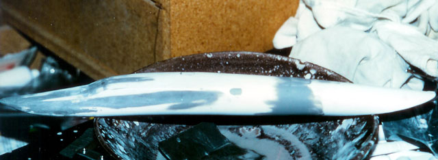
The gooseneck parts were prepared and glued together. But, the shape
still looked wrong. I studied the plans, studied the parts, studied the
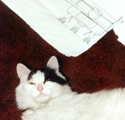
photos, moved ‘Bert’ (my deceased cat) off the plans and
studied them some more. Then I picked up razor saw and hacked off the
bottom (of the goose neck, not Bert) to improve the taper.
After more putty and sand, sand, sand, dunk (water), it looked right.
Click the thumbnails below
to view larger images:
But now what!? The goose neck, when dry fitted to the spine, stuck up
like a . . . well, let’s just say it stuck up. I had to cut a hunk of
the goose neck out keeping the length the same (triangular cut) but
change the angle. I re-glued it, strengthened the inside with scrap
plastic, pucky, sand, sand, sand. Surgery complete! Patient looked like
it would recover nicely!
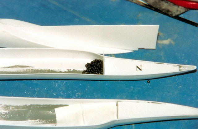
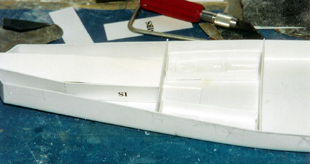
I moved on to the main body (it’s hard for me to call it a fuselage)
that mounts below the wing. These parts fit fine but I had to do lots of
measuring, checking and more measuring, etc to get the gear centerlines
lined up with each other. The dry fit of the main body parts are shown
below. I wasn’t a stickler about the cockpit but I was about the
intake splitter plates. I had to do a little engineering to incorporate
them – even though they too are hard to see.
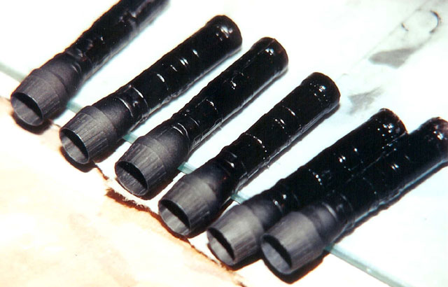
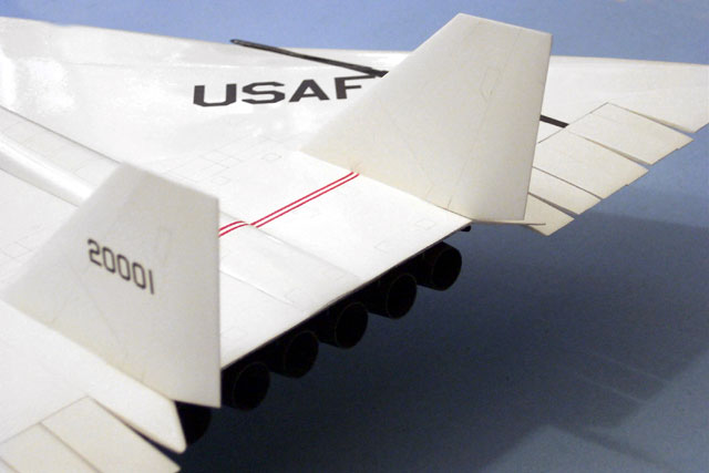
The engine compartment I painted gloss black so you can’t see in past
the exhaust nozzles. The nozzles were made by taking
(stealing) one from another kit on my shelf (sorry, I don’t remember
what kit . .. a jet I think . .. . ! ). Anyway, Mr. Bill Ferrante a San
Jose IPMS member was kind enough to make a mold and cast me 5 more. Well
6 actually, I put the original back into the unknown nozzle-less kit.
Click the thumbnails below
to view larger images:
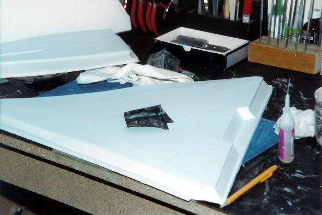
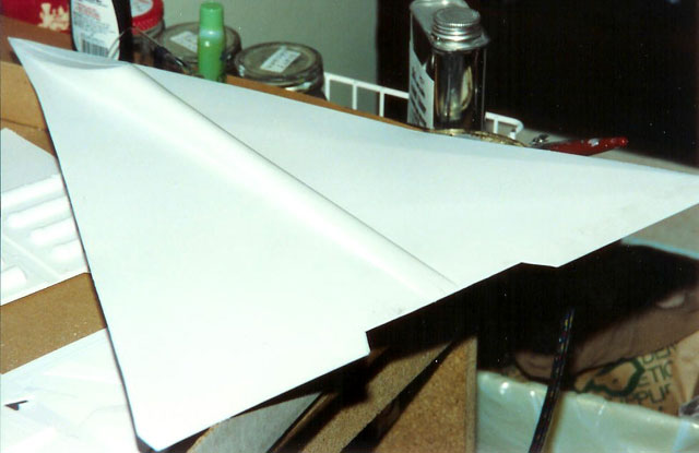
The wing, although big, was relatively easy except I just had to cut out
the “tail feathers” and glue them as seen in the photos that I had – all
different angles. The body was aligned and glued to the
wing. Matching centerlines and getting the wing level wasn’t too bad.
Click the thumbnails below
to view larger images:
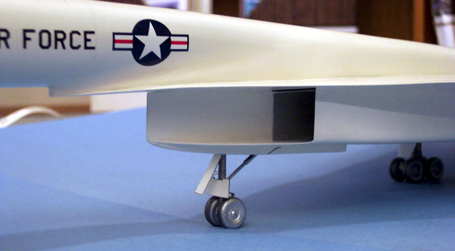
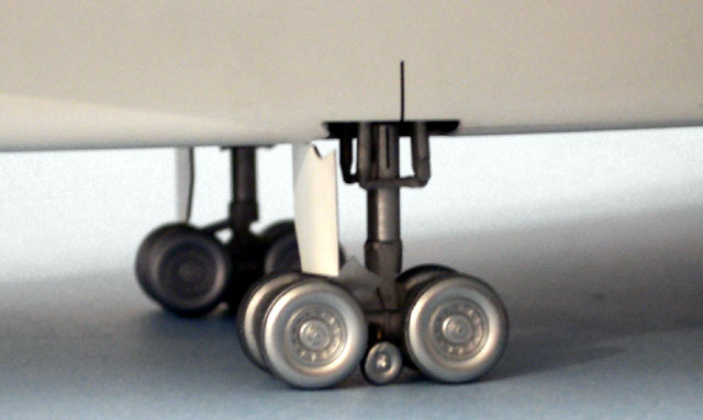
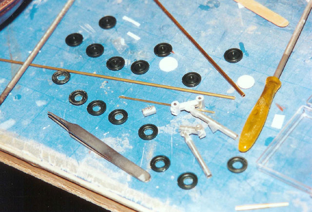
While the glue was drying, I would tackle the landing gear. I spent more
time sizing metal tubing and wheels until I got the correct combinations
. . . or close enough.
Now, the real fun began – attaching the goose neck to the spine which is
attached to the top of the wing. But wait a minute.
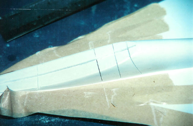
 The wing has a funny
but noticeable camber effect right at the front of the delta plan form.
This part had to deflect a little to make it right, but the spine, right
where the goose neck is to be glued, was a terrific stiffener. I had to
make three cuts in the spine to match, or come close, to the
correct contour of wing/intake. The wing has a funny
but noticeable camber effect right at the front of the delta plan form.
This part had to deflect a little to make it right, but the spine, right
where the goose neck is to be glued, was a terrific stiffener. I had to
make three cuts in the spine to match, or come close, to the
correct contour of wing/intake.
The goose neck was supposed to be attached with a single sheet of
plastic as a spar, but I beefed it up. I did not want that joint to
fail! A thicker piece of plastic glued with plastic cement plus Two Ton
epoxy – that should hold it! Now it’s as strong as an ax handle!! The
main body/wing section was placed on a piece of particle board (flat). I
used a triangle, right angle tool, my eye, a boy scout compass, smoke,
mirrors – anything I could find to help me line up the goose neck (6
degrees of freedom) with the main body (6 degrees of freedom). This took
two evenings before I was satisfied. I held my breath and glued it
hoping it wouldn’t sag or turn after the clay props and tape were
removed. It didn’t!
I replaced the kit vertical stabilizers and canards with sheet plastic.
First to be more scale like (thinner), 2nd only one piece and, 3rd
flatter and harder plastic. I added brass dowel pins for a firm joint.
Finding and making the holes so everything lined up was a challenge. I
had to move my plans guard, Bert, to consult the plans frequently. Some
times he didn’t like that. The first thumbnail below is Bert’s version of Clint Eastwood,
“So you think you’re gonna move me . . .Huh, punk . . . .Go ahead . . .
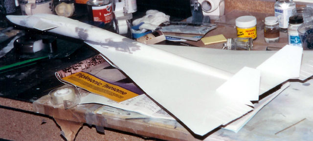
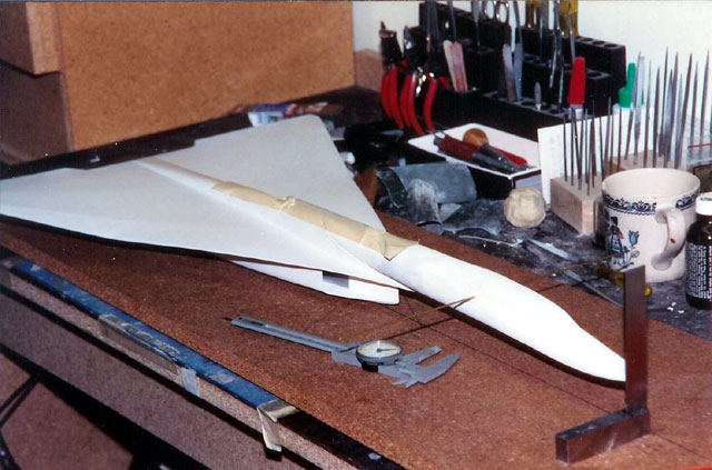
. make my day!” The next thumbnail shows the intake area and some of the gooseneck
to main body joint. Not quite done with sanding but getting there. P I
sanded the entire aircraft with 600 wet. I felt like I was sanding the
Golden Gate bridge! The final photos shows the model just before painting.
Click the thumbnails below
to view larger images:
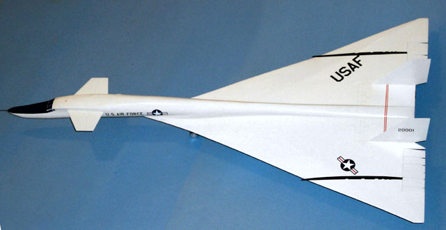
I hosed on Floquil Reefer White + Crystal Cote and wet sanded with 1000
wet paper between each of the four coats. Sand, sand, sand, dunk . . .
remember . . ? I over-coated with pure Crystal Coat, put on the decals
and some pencil panel lines. (I do not suggest doing pencil lines. I
think it’s the only thing on the model I’d change.) I added another coat
of Crystal Cote, the gears, doors, pitot, engines, a couple of blade
antennas – done!
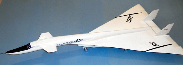
Even after all of the ‘fixes’ this is, no doubt my favorite airplane and
my favorite model.
As I look at these assembly photos I first of all
applaud Contrail Sutcliffe for even coming out with the kit, but with
all due respect to them and at the risk of sounding immodest, I feel
that on this one, I truly turned CRAP 2 CAKE... but, that’s what vacuforming
is all about!
Click on the thumbnails
below to view larger images:
Model, Images and Text Copyright © 2003 by
Bill Dye
Page Created 05 March, 2003
Last Updated 17 March, 2004
Back to HyperScale
Main Page
|
 Home |
What's New |
Features |
Gallery |
Reviews |
Reference |
Forum |
Search
Home |
What's New |
Features |
Gallery |
Reviews |
Reference |
Forum |
Search