|
Airborne Offspring
Zveno 6 - TB-3/M17 &
I-16 Type 5
|
|
|
Zveno 6 - TB-3/M17 & I-16
Type 5 |
Model, images and text
by Aleksandar Šekularac

available online from Squadron.com
This story came to me in splinters, over years. I
would see a picture in a book, or read a line, or two about it. The
interest would reverberate for couple of minutes, and then the whole thing
got forgotten. Like a big puzzle, it was building itself in recesses of my
subconscious.
And then it happened. These people from Ukraine came out with the most
unusual kit. The image on the box looked familiar, but strange at the same
time. An oddity on hobby-shop shelves. Yet, it was there, and stream of
information collected over time came back in a flash. How was I to defy
it? The itch for this subject overwhelmed me, and I started digging
deeper. After just couple of days I was spellbound. Here is an amazing
story I discovered.
Tale of “Zveno”
The idea of coupling, and uncoupling aircraft in
flight is almost as old, as the aviation itself. Several free thinkers
worldwide, throughout the 20th century tried to construct a viable flying
aircraft carrier. Nobody went so far as the Russian engineer, Vladimir
Sergeevich Vakhmistrov, whose work allowed for some amazing achievements
during the golden age of flying. This is the only case in history where a
flying composite, consisting of mother-ship and two parasite
fighter-bombers, was successfully used in combat.
Vakhmistrov started work on his idea of the long-range bomber escort in
1931. It was called “Zveno”, and its first incarnation involved two
modified I-4 fighters strapped on top of the wing of TB-1 bomber. The
first flight of this composite was successfully carried out on December
3rd 1931, over Monino base near Moscow.
Many more modifications, and flight-tests followed. The parasite planes
were replaced with I-5’s, then a new, and bigger mother-ship arrived:
TB-3. When Polikarpov I-16 monoplane fighters became available
Valkhmistrov was eager to try them. Two I-16s were strapped under the wing
of the big bomber, and this became the most successful configuration,
known as Zveno 6. Carried on pyramidal suspension system, fighters were
mounted under the wings of the TB-3 before flight. Connected to their
behemoth “mother” with umbilical chords, they were feeding on fuel and oil
during a joint flight. On take-offs, all six engines were throttled up,
and roared in unison down the runway. It must have been such a sight.
Series of flights were carried out, with fighters succesfully uncoupling
from the bomber. Zveno 6 was finally accepted for production by NII-VVS
(Scientific Research Institute of the Air Force) in December 1936.
Next was an attempt to enable the fighters to return to the mother-ship.
Vakhmistrov had an idea of developing completely new, airborne
fighter-plane for Zveno, which wouldn’t have landing gear, and as a
consequence be smaller, lighter, and faster. This would also solve the
problem of returning range of the fighters. A complicated tubular trapeze
system was designed to extend and catch approaching I-16. Then, the whole
thing would retract back, under the shadow of the gigantic wing. After
several trials the process of reattachment was deemed too sensitive and
complicated for an average-skilled pilot.
The pinnacle of Zveno project came with “Aviamatka” flight, which took
place in 1935. For the purpose of so called “airborne alert” no less than
five different fighter planes were attached to one TB-3. Despite a
successful flight, this concept was discarded by critics as just another
publicity stunt by “Vakhmistrov’s flying circus”.
Final evolution of the composite that saw outbreak of the war, was based
on Zveno-6, and was known as SPB Zveno. I-16s parasites changed their role
from air defense to high speed dive-bombers. The success and effectiveness
of SPB Zveno in its 30 combat missions was striking, especially
considering that both TB-3, and I-16 fighters were already obsolete by the
time they were called to defend the motherland. Bridges over Danube and
Dniepr, oil fields, and docks of Constantsa, and other targets all fell
victim to Zveno raids. German Field-Marshal, Erich von Manstein, in his
memoirs implicitly blamed final loss of Stalingrad battle on Russian
bombing of the bridge over Dniepr at Zaporozhje in August 1941. Two Zveno
SPB composites were responsible for this attack. The bridge was not
repaired before autumn of 1943, much too late for the fate of German
troops. Despite their successes, the truth about Zveno missions remained
secret to the outside world, long after the end of the war.
A Rant About this Kit
ICM company from Kiev, became a synonym for Soviet
aviation and mechanization in scale from Great Patriotic War. Some time
ago I was working on a MiG-3 kit made by these people, and thought how new
age finally came, when one can enjoy a kit of something that doesn’t begin
with letter F, or Bf. Little did I know.
Few years passed, and ICM released a kit of Tupolev TB-3, Russian
colossus, one of the most comprehensive 1:72 aircraft kits in history.
This was clearly somebody’s labor of love. Attention to detail, and
accuracy of this plastic jigsaw-puzzle indicates painful dedication to an
object of passion. This is not a cookie-cutter kit developed on marketing
research. Weekend modelers wouldn’t be interested in something this
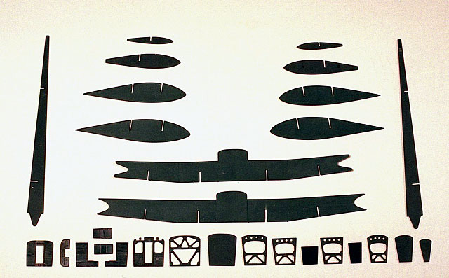
obscure, and complex. The kit builds like a real aircraft, beginning with
lot of flat, structural parts: spars, ribs, bulkheads, frames, and
formers. They all cry for some attention before they will fit properly.
Another ICM box appeared shortly after the initial
kit release. It was a so called Zveno-SPB. So called I say, because what
is in this box is a great kit of a true farce. We who care know this, and
good people from ICM must have known it, as well. The excellent model of a
TB-3/M-17 was thrown in a box with two excellent kits of late type I-16
and the box was called Zveno-SPB. Well, the truth of the matter is that by
1940, old TB-3/M-17 types were replaced by more modern TB-3/AM-34FRN, and
these were the mother-ships flown to combat. The difference between these
two types are drastic: engine nacelles, main landing gear, nose
compartment, tail turret, just to name a few most obvious differences. So
the question is why did ICM do this? They could have altered I-16 kits to
produce accurate early type-5 variant, and call it Zveno 6, or Zveno 7
(this is what I ended up doing for this model), or they could rolled the
dice, and produce whole new TB-3/AM-34FRN, for accurate Zveno-SPB. For
someone who doesn’t care about authenticity this is probably not a
problem, but then again, this kit is not geared towards those who don’t
care. My theory is that the bean-counters finally overpowered
master-modelers in ICM, threw them kicking and screaming in the basement,
and locked the door behind... Oh well, be it as it may, this kit is still
worth more than they ask for, in my humble opinion. It is the only scale
model of a very unique part of the aviation history, and that is enough
for me to feel grateful.
And then, lets not forget Eduard photo-etched set for TB-3 (72-335). Many
details for the cockpit, gun-rings, engine service platform, spoked wheel
rims of course, and multitude of barely visible parts bring the model to
the whole new level. The expression that I use to describe working with
these bits is “molecular modeling”. Well, for anyone who didn’t have
enough with 400 parts from the ICM box, Eduard ads some 150 to that
number.
Most modelers have an instinct to start a new
aircraft kit in the cockpit. That is usually a good instinct to have, but
this particular model requires something a bit different. As I mentioned,
there are no fuselage halves to sandwich the pilot compartment between.
There are no wing halves either. I started by laying out all the
structural parts, and corrugated surface panels on the floor, and pondered
where to really start. Two wing spars include main fuselage frames, and
everything else extends from there. The wing of this pterodactyl had to be
done first. I started to sand every corrugated skin panel back-face, as
these lay on the inner structure, and require even thickness to look
properly when assembled. Exquisite surface detail prevent standard
finishing methods on this model. Luckily, I realized at the very beginning
that there can’t be any seam-sanding or puttying on the surface of TB-3.
All panels have to align perfectly, and gluing has to be done from the
inside. I adopted a strategy of using liquid welder cement, and it’s
capillary action to run it along inside edges of all panel joints and
structural elements. This was a main method for building the wing and the
fuselage from myriad of parts.
1. The Wing
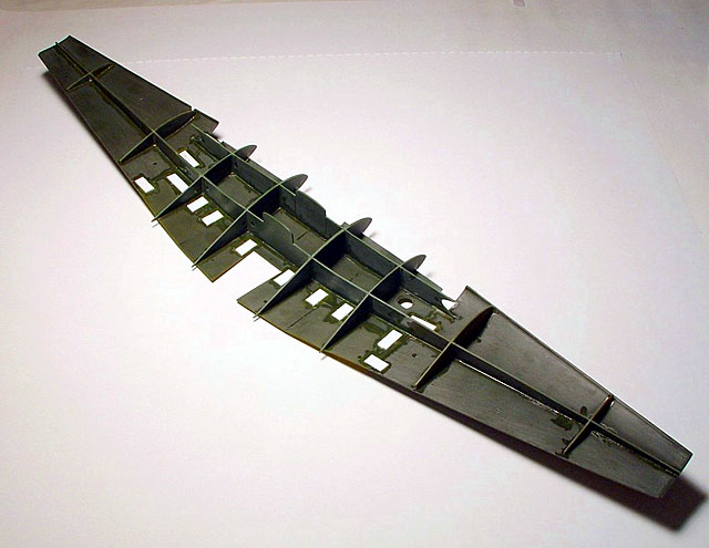
Wing construction started with spars and ribs that
build into a support frame for surface elements. I can’t emphasize enough
the importance of making this structural frame straight and parallel.
Everything that will follow depends on this crucial step. After finished
the frame, I started to attach bottom skins for the wing surface. All of
these panels are but-jointed, and it is a good idea to support the seams
from inside with overlapping plastic pads (from styrene stock).
With the wing of this size, real aerodynamic
properties become obvious even in 1:72 scale. Achieving symmetric and
consistent dihedral, as well as the proper angle of attack distribution
over the span takes a lot of effort. I did some tweaking as I assembled
upper surface elements. Applying some pressure, and torque before glue
cures is the most effective way to adjust everything. When the wing is
boxed in, with lower and upper panels locked on the frame, it becomes
rigid, as if carved from a solid piece. Leading and trailing edges are all
separate parts. I used more of inside seam-pads, as described before, to
align them with the main wing. Wing tip elements, had some trouble
fitting, so scalpel was required. Two part ailerons were also tricky to
fit and align on the supporting structure. After I finished the wing,
grandness of this aircraft had stricken me for the first time.
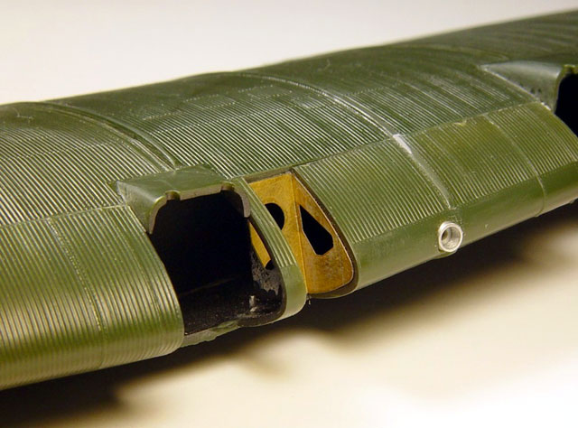
At this point I blanked off cavities for the ventral turrets, as some
available pictures of Zveno aircraft show this. I cut a leading edge panel
of the extending servicing platform for the inside port engine, and
installed photo-etched plug for this structural detail. I also made
landing light sockets on the port wing from pieces of brass tubing.
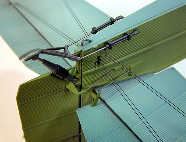
Next task was to carefully measure and drill small
holes on the bottom of the wing surface for fixed main landing gear, as
well as pyramidal parasite fighter trusses. I planed ahead to anchor all
these connections with steal wires and pins, anticipating heavy and
fragile model. I drilled two holes of a bigger (~4mm) diameter and made
ducts from styrene tubing for parasites fuel/oil feeds, and small mounting
hoists from bent steel wire. After that, I let the wing alone for a while.
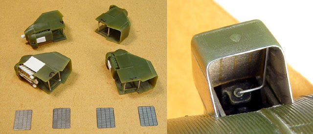
2. Interior Compartments
Open cockpit, bombardiers compartment in front, and
engineers compartment in the back, as well as the back gunners stands are
all present in the kit. They can be built in a very convincing interior of
the TB-3. In addition, they provide frame support for the fuselage surface
elements. Before starting work on the actual cockpit I had to build the
framework for the nose compartment. Some walls were thinned down for the
scale appearance. Same was done for the aft of the fuselage.
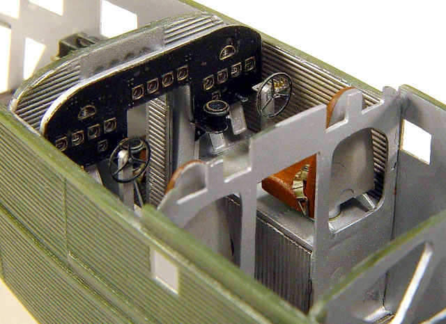
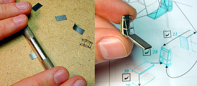
Eduard photo-etched parts enhance the area of the
cockpit immensely. The instrument panel is a sandwich of brass, acetate,
and plastic, which is my favorite for representing realistic instruments
in all scales. Additions of throttle quadrants, finer “steering wheels”,
ruder pedals, and seat harnesses are also very welcomed. When finished,
this area looks like it should.
Many parts were scratch-built in the bombardiers, and
engineers compartments. I tried to make best use of the parts I found in
the spare box: like radio boxes from the Mosquito in 1:48 scale, but there
was also lot of place left for “evergreen” tubing and brass wire. Most of
this detail ended up shrouded in darkness, once the fuselage was closed,
but at least for a while it looked impressive, and it gave the model (or
the modeler) a sense of completeness.
And now, for the first real challenge of this big
model. All the small windows on the sides and the front of the fuselage
come as separate pieces that have to be framed in the orifices in fuselage
panels. All of these were oversized for the corresponding openings. Being
an inherent optimist, I reasoned that this is still much better then if
they were all undersized. I sanded, and then polished each clear piece in
width, height and thickness. When this was done, one problem remained. How
to attach and align single windows to the fuselage sides, only using thin
sides as a bonding surface? I fancied the idea of leaving this step for
the end, after the painting is done, but rational part of me knew that
there is a slim chance of doing this without ruining paint, or detail
around the window. To further complicate the problem, there is full
corrugation detail inside and out on all nose side panels. I don’t
consider myself a radical person, but at this instant I knew that there is
no civilized way around it. I sanded the corrugation from all insides of
fuselage panels, save the are of the open cockpit, where it will be most
visible (luckily there are no windows there), then I positioned all the
windows in their places, and did the unthinkable: poured superglue across
inside surfaces and windows. Then, I waited for the glue to crystallize...
While feeling unique sting of CA vapor in my nose, I wondered if I just
destroyed the model.
The fuselage side panels now resembled a landscape of
volcanic islands, and all the windows were fogged. It was time for sand
paper again. I rubbed, and I scrubbed, rubbed, and scrubbed, and started
to realize that my plan had worked! The windows were now fused with the
surrounding plastic, looking like there were there from the beginning.
Finer grades of sand-paper and Tamiya rubbing compound brought the old
shine and transparency back, and the job was done.
3. Fuselage
Similar to the big wing, fuselage is assembly of
corrugated skins over the structure made of bulkheads and frames. It is
again important that everything is aligned inside, for the outside to look
symmetric, straight, and proper. Front and aft fuselage are separate
assemblies and they meet with side panels, arching across the airfoil of
the wing. I have built all the inside detail on the bottom panels of the
fuselage, then glued the sides, and then assembled the front and the aft
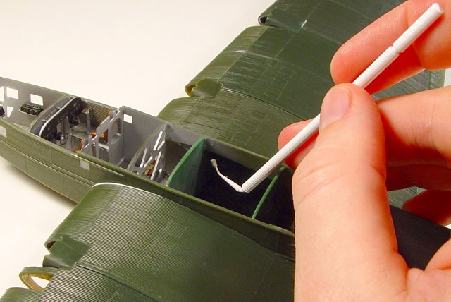
fuselage to the wing, before actually closing the top off. This was done,
to allow access to the seams for running the glue from the inside (I tend
to adhere to the previously proven methods, if I can). By this time the
process required a special applicator with a cotton micro-tip, bent such
that it can reach inside corners.
Even with the greatest care, I found that the
fuselage needed some side shims to form a air-tight connection with the
wing. This is due to the fact that front and aft fuselage assemblies are
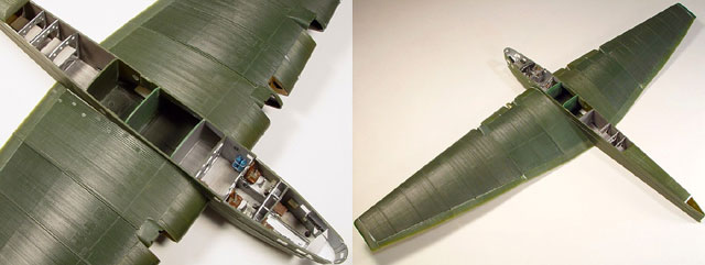
already finished when everything comes together. I made these shims by
sanding a piece of styrene stock to sharp edge on one side, then inserting
it in the gap where the wing meets the fuselage side, and then tracing
with a black pen along profile of the wing. I then cut this shape out, and
with little trimming I had a perfect fitting insert, which actually ended
up looking like another row of corrugation of the surface (this is visible
on some construction images as the white stripe on port wing root). When
glue dries, the structure is once again very rigid, which is in contrast
to the number of fragile parts that it consists of.
When the fuselage front was fully assembled I tried
to attach big faceted bombardiers glazing in the front. It didn’t fit
right. It was wider then the fuselage sides. When I tried to adjust the
shape by exposing it to hot water, it just warped, fogged, and then
finally broke. Well, it was time for scratch-building again. Using Falcon
acetate sheet I measured and then bent the facets for the front bit, and
cut the bottom for this part out of flat piece of clear plastic from the
spare box.
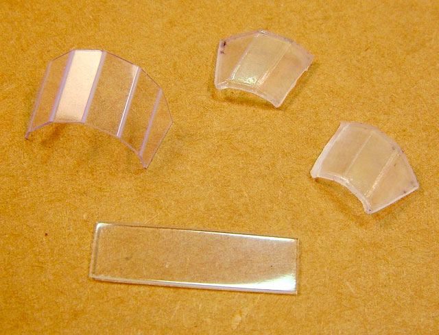
While I was at it, I built the windscreen for open
cockpit using the same method. Part that came with the kit had a chipped
corner.
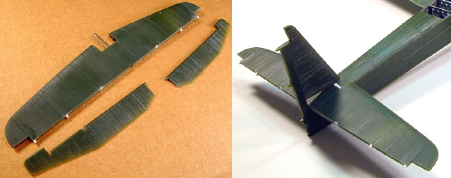
4. Tail Surfaces
This is were I encountered second big problem. Both,
vertical and horizontal tail surfaces have only point contact with the
fuselage; on the real aircraft they were secured with rigging. While I
planed to have functional rigging for the tail, I had to somehow attach
the tail parts and manage not to brake fragile bond until the model is
almost done. Further, the horizontal tail piece in my kit was warped out
of shape. I am convinced that this piece of plastic was prematurely
extracted from the mould, and then warped as it was cooling down. I once
more tried the trick with hot water, this time with greater success. I
managed to straighten the part in horizontal plain, without destroying
surface detail. Then, I sanded down the hinge line for the elevators, to
produce a straight line. I rebuilt the hinge detail, and also bored holes
and attached two syringe tubes axially to the root of the horizontal tail,
to produce support with the adjacent fuselage bulkhead.
I needed to pre-drill a lot of small holes for future
rigging, as well for the attachment of the tail skid, and all the tail
mechanization lines. After this, the tail was assembled (I made another
plastic shim where the top end of the fuselage panel meets with the
horizontal tail). While preparing the tail skid elements, I replaced all
the links with steel wire, and main skid oleo with piece of syringe
needle. This gave more life, and much more stiffness to this spider-web
contraption. Fruits of this labor were obvious much later, when everything
was painted and assembled.
Functional rigging of the tail surfaces was done by
threading nylon monofilament (sprayed in gun-metal) through pre-drilled
holes and securing it with droplets of thin super-glue.
5. M-17 Engines:
Four engines of the big bomber took a lot of time to
build and detail. Three of them were built more or less from the box, but
with more detail added on the back side of the radiator exit, where
nacelle is open and allows some view to the engine. I also thinned out all
exposed nacelle edges, as these parts are quite thick. Radiator back faces
are provided as fine photo-etchings in Eduard set.
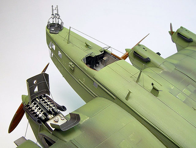
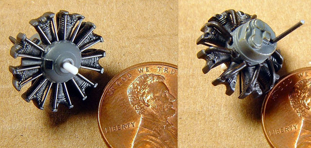
I decided to open up the top cowling of the inside
port engine, and show it with the extended service platform. ICM kit
engines are rudimentary, but that is sufficient if everything is left
closed. I first intended to use resin Shvetsov engine from “Engines &
Things” company, but this proved to be little more than what is in the kit
already. So, general scratch-building material was used again. 1:72 is not
the ideal scale for making such small parts, as rocker levers, or oil
pumps for engines, but with couple of good reference photos that I found
on the web, and extra stock of patience, engine turned out pretty
impressive.
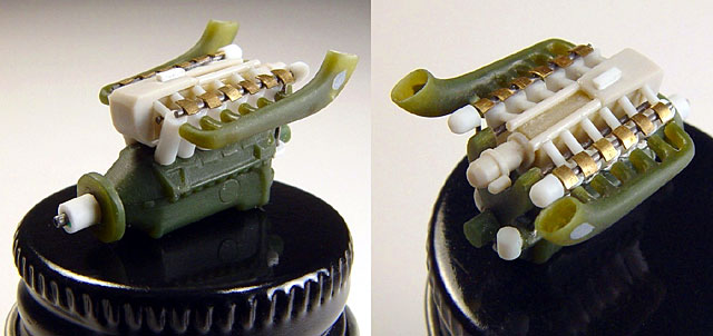
I also drilled out ends of exhaust envelopes and
attached them to the cylinders using steel pins. When this big job was
done, it was time to feast on the service platform, which is given in
Eduard set, as the multi-part photo-etched assembly. This is a little
jewel in itself, but it takes some skill to assemble. This part forms the
leading edge of the wing in its closed position, and has complex curves to
it. I used cylindrical surface of my pin-vise to roll the parts around,
and then carefully super-glued everything together.
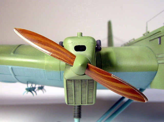
Next were propellers. I read several tips on the
internet how to represent natural wood in plastic, but this was first time
I was about to try it myself. It must have taken five tries before the
results were satisfactory. But, it was worth it. So, here is the secret:
airbrush a base-cote of tan acryl color, and let it dry thoroughly. Next
day, mix a wash of wood color using artist oils, and mineral spirit as a
solvent. Mineral spirit won’t attack acryl basecoat, so you can hand brush
layers of color and achieve very realistic wood grain. You have experiment
a bit to find a good hew, but as an example I mixed yellow ochre, burnt
sienna and burnt umber for this purpose (I even mixed tubes of different
brands).
As I said, it takes some practice but the result
should be very pleasing.
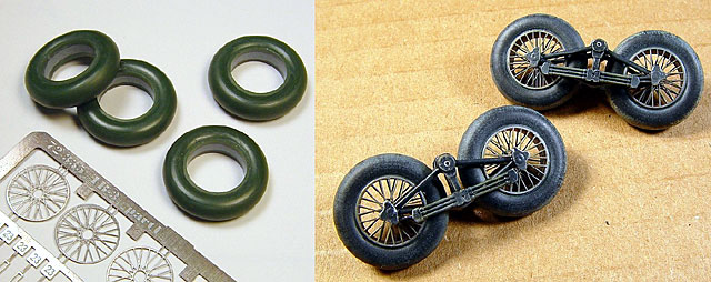
6. Where Rubber Meets the Road
Main landing gear is another focus of interest on
this extensive kit. Tandem main wheels with their buggies, and long tripod
legs look impressive right from the box. However, most photographs of TB-3
bombers show wheels with uncovered spokes, while the kit wheels are solid
pieces. One of the highlights of Eduard set are spoke rings for main
wheels. I gouged out halves of the kit wheels, leaving just the tires, and
glued them together. I then filled the hole left inside the wheel rims
with putty. The spokes required a lot of attention, as only a very thin
ring comes to touch with plastic tire. Needles to say, super-glue is a
weapon of choice here. I added spindles made of brass and assembled the
supporting structure. On several photographs I noticed that tubular
structure of swivel landing buggies seem to be black, or very dark color,
in contrast to the light undersurface of the wing. I pained it black and
then weathered it with earth tones.
I drilled small holes in all the junction points of
the landing gear struts, and reinforced them with steel pins. The swivel
point between the wheel buggy and the main strut was also replaced with a
syringe needle, but this was left unassembled to later fine-tune the
stance of a finished model. The landing strut tripods were glued to the
bottom of the wing.
Finally, this big bird started to take shape.
7. I-16 Early Type-5
After reading and researching texts and pictures of
Zveno, I was certain to a high degree that only Polikarpov I-16 type 4 and
early type 5 were used before the war started. Most pictures show Zveno-6
layout with older type-4 fighters, but others also show type-5 being
released from the air from the TB-3/M-17 mother-ships. It is easy to
conclude that these replaced type-4 models in later years of the project.
On the other hand, ICM provides two type 24 fighters, for their “SPB”
version. Since my decision was to be historically accurate as much as I
can, I had to backdate small kits to represent pre 1938 type 5 variant.
For one part this implied deleting surface details, but there are also
some major differences that required greater attention. For example, early
type-5 aircraft had full span ailerons, where the later models had
shortened version. I just re-scribed the extra length of ailerons, when
the wing was assembled. Other changes were harder to make. Early models
had 8 exhaust outlets, while later models had 6. Propeller spinners also
differed in a manner where sand paper alone could not solve the problem.
Not to mention sliding enclosed canopy on the early models...
When I have question about something old, Russian, and flying, I usually
ask my friend Erik Pilawskii about it. He is as much as one can get a
walking encyclopedia about obscure objects with red stars on them. Well,
when I asked him about above-mentioned problem, he recommended getting
Amodel kits of early I-16 type 5 that are very accurate. I found these
cheap, and got two. While they are indeed very accurate, they also look
crude compared to the nice plastic in the ICM kit. The sliding canopies
are thicker than what I would expect T-34 armor to be in this scale. I
decided to use all the necessary parts from Amodel boxes to backdate ICM
kits. The bottom cowling panel was cut from the wing, and modified to fit
properly, and spinners were separated from the propeller blades, and
gouged to accept a new propeller.
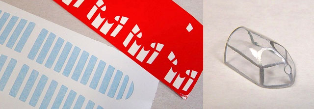
In the meantime I managed to convince my other good
friend, Aleksej from Gremlin Models, to help me with the canopies. I’ve
sent him one of the clear bits from Amodel kit along with some scale
drawings of I-16 early type-5 that I found on the web, and what came back
was a dozen, or so heat-and-smash canopies along with vinyl masks for
framing, and for correct outer wing ribs! I don’t know how Aleksej does
this, but he does it really good. If you haven’t seen size of this canopy
in 1:72 scale, it is minute, and you can barely manipulate it with tips of
your fingers.
With all the problems solved, I proceeded to modify
the kit. I drilled pairs of holes on top of the fuselage, in front of the
cockpit. This is to allow some natural light to penetrate to deeply
recessed instrument panel. I also made rails for the sliding canopy from
the styrene string, and scratch-built telescopic gun sights from syringe
needle, and some brass sheet. ICM kit provided very detailed radial
engine, so I decided to leave some cowling panels open on one of the
fighters. I added details to the engine compartment, like push-rods made
of steel wire, and exhaust stubs from (again) syringe needle (people in
the drug-store always look at me with the great suspicion when I ask for
large quantities of syringe needles of different diameters).
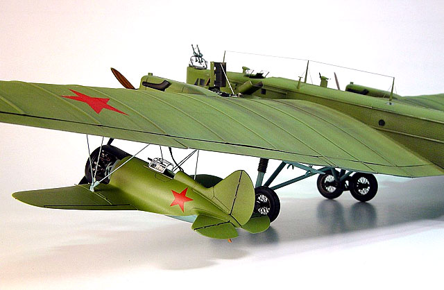
When two fighters were assembled it was time to
position them under the wing of TB-3 and build the support structure.
Plastic struts given in the box looked too thick, yet fragile, and
furthermore they were with profiled cross-section. While this is correct
for later SPB composites, Zveno-6 had simple tubular trusses. I used kit
pieces just for approximate measure of length, and made new ones using
steel wire. This was one of the most time consuming steps, as the trusses
had to be made perfectly symmetric, and to the right dimensions. When I-16
fighters are suspended, they have to be aligned in all three axes, to one
another , and with the big carrier. They have to appear horizontal, while
hanging from the wing that has pronounced dihedral. All this can be better
described with this picture of the model during one of the final
test-fittings.
I added fuel, and oil valves on the starboard sides
of the fuselage, and little “Ratas” were done.
8. Last Details
Several times while working on this model I was
tricked to believe that I am almost done. Once again, there were more
things to be finished. All over the surface of TB-3 there is a multitude
of small details: hand grip railing, radio antenna poles, melon antenna in
front of the main windscreen, several pitot, and venturi tubes, and to top
it all, a miniature power-generator. The wire for the main radio antenna
was once again sourced from the nylon monofilament, sprayed with gun-metal
paint.
After long, rigorous course of following historical facts, at this point I
finally yielded to the call of artistic freedom. Most photos show Zveno
flights to be unarmed, with guns taken from defensive positions of the
bomber, as well from I-16 fighters. But the gun rings provided in the ICM
kit, as well additional photo-etched detail provided for them in the
Eduard set, were to good do be ignored. I decided to call my model an
ultimate pre-production Zveno-6, all dressed up, and ready to go. After
finishing defensive positions of the TB-3, I knew I made the right
decision.
Finally the time has come to apply some paint. But, before that, mask all
the glazing and openings...
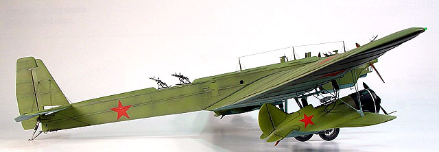
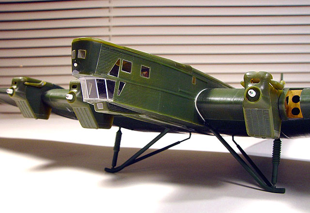
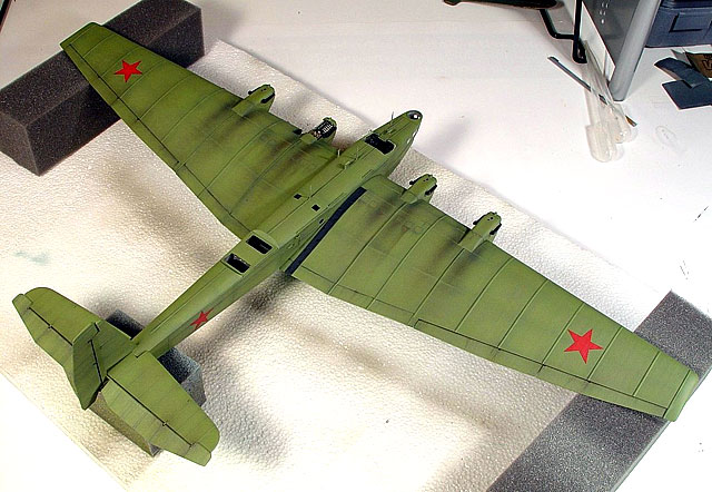
Jack In The Green
If you like elaborate camouflages and colorful markings, look elsewhere.
Zveno’s were big, rectangular, and irritatingly bright green. It is that
elusive shade of AII Green that nobody knows how to match. Nobody but Erik
Pilawskii. He kindly provided me with exact RGB definition for colors used
on this model, so I was able to happily mix my own brew from U.S. Interior
Green, some Neutral Gray, and a drop of White. Underside surfaces were
painted with Russian Underside Blue (Model Master bottle), with a tad of
French Blue added to the mix. The I-16 fighters are more of the same
color, with cowls painted black.
I started painting process by spraying the whole surface of TB-3 with
light-gray acryl primer. This was done to reveal any remaining surface
imperfections, but also to provide nice high-contrast base for pre-shading
with black. Black paint was sprayed along panel lines, hinges, and
especially around, and behind engine nacelles. I then started applying
undersurface blue, starting from the middle of the panels, and working my
way towards the edges. This allows for controllable variation of
weathering finishes, from extensive to subtle. When the underside was dry,
I masked the demarcation line and sprayed AII Green on upper surfaces,
using same technique.
With the model of this size, handling becomes a problem. I made a rig,
consisting of a big Styrofoam base, and padding-foam cubes, for wing and
tail supports. In this way I was able to handle and rotate the base
without touching the model.
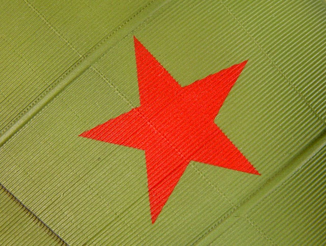
Applying stars on TB-3 corrugated surfaces proved to
be a challenge. Early in the construction I realized that I won’t use kit
decals. They were printed in some orange hue, stars were not symmetrical,
and they simply wouldn’t conform even to the mild curves. After few tests
with different spare decals, it was clear that the stars have to be
painted on. I designed stars of the right size using a computer, and then
printed these outlines on the back of the sticker backing paper. I peeled
of and disposed of the sticker surface, and then carefully applied 3M tape
on its place, over the exposed glossy backing, taking care that the tape
fully covers the area where the stars are printed on the back. Several
layers of the tape were needed to cover everything. I cut out the star
masks following the outline, applied them to the surface of the model,
sprayed red color, and removed the masks. The result, well you can judge
for yourself.
More weathering was done with thinned over-sprays of
lightened base color, and some dark browns for exhaust streaks behind
engines. I also applied washes of browns along some panel lines, and along
control surfaces, adding spill-outs of fuel and hydraulic fluid where
appropriate. Final touch was paint-chipping, which I did using thinned
silver paint applied with a “0” brush. This proved to be an overdone
effect in 1:72 scale, so I made another transparent spray of base AII
Green that subdued the look. The TB-3 was done.
For I-16 fighters I made same steps as with the big bomber. Of course,
process was much quicker this time around. Gremlin Models wing masks
worked very well. One thick spray of Gray was applied with the masks on,
and then they were removed. After lightly polishing newly established
detail, final cote of paint was sprayed. Subtle ribbing detail is visible,
even beneath decals.
The stars for the fighters came from spare decal-sheets, and I applied
them to under-wing surfaces and sides of the fuselage. With some more
weathering I-16s were done too.
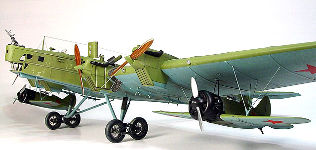
Final assembly of small parts included canopies, propellers, gun rings for
the bomber, and then I permanently attached fighters to the suspension
trusses bellow the wing of TB-3. I fashioned oil and fuel hoses from
insulated wire painted dark gray, and attached them with drops of
super-glue.
I pulled back in the chair, and took a deep breath, still smelling curing
solvents in the air.
Click the
thumbnails below to view larger images:
Sometimes I run into a book, a novel, and when I
start reading it I cannot stop. It doesn’t happen often, but when it does,
it is a sensation worth cherishing. The world of the novel fuses with the
outside world, and for a while I am living in two realms. Working on this
model, and researching surrounding history gave me similar feeling.
Eight months passed since I first opened the ICM box. Now, I was again
looking in the same box, checking through the remaining sprues, for
anything forgotten. I felt satisfaction, relief, but also sadness that
this journey is at its end. Model was done, and displayed in the big glass
cabinet. It was time to clean the work bench.
This was so far the biggest modeling project for me. I tried a number of
techniques for the first time, maybe I even invented a couple. I returned
to 1:72 scale after many years. Despite its limitation, it provides great
possibilities for subjects that would be really hard to manage in bigger
scales.
I would also like to mention couple of people, whose help and enthusiasm
were much welcomed during this project. Erik Pilawskii, who I consider a
kind friend, provided his knowledge and expertise on several occasions.
Aleksej Ilić, form Gremlin Models, is another old friend, and this time he
stretched across the ocean, and provided some amazing hand-made vinyl
masks and acetate canopies. Thank you both.
ICM 1:72 Zveno is not easy kit to build, and it is far from perfect, but
it is one that can turn into a precious stone if one polishes all its
facets. Scale modeling for me is about patience and attention to detail,
and this model requires both, in abundance. It is a real treasure for
adventurous souls.
-
"Combat Composites”, Col
Vladimir Lesnitchenko, Air Enthusiast No. 84
-
“The Tupolev TB.3”, Harry
Truman, Scale Aviation Modeller International, vol.7 issue 2
-
“Polikarpov Fighters in
action pt.2”, Hans-Heiri Stapfer
-
Zveno “Aviamatka”, Ken
Duffey, web article
-
vast expanses of WWW
Model, Images and Text Copyright © 2003
by Aleksandar Šekularac
Page Created 16 July, 2003
Last Updated
17 March, 2004
Back to
HyperScale Main Page |
 Home |
What's New |
Features |
Gallery |
Reviews |
Reference |
Forum |
Search
Home |
What's New |
Features |
Gallery |
Reviews |
Reference |
Forum |
Search