|
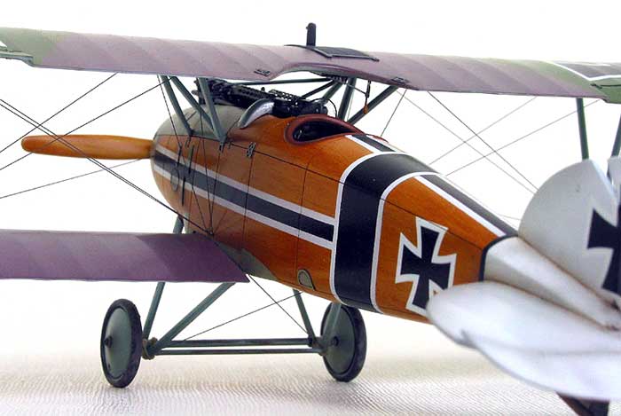
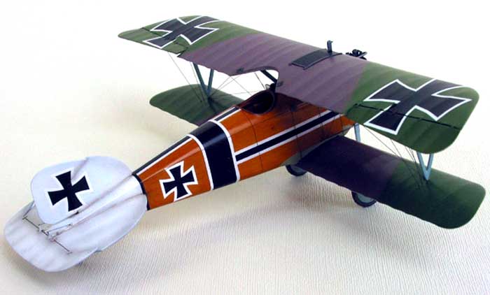
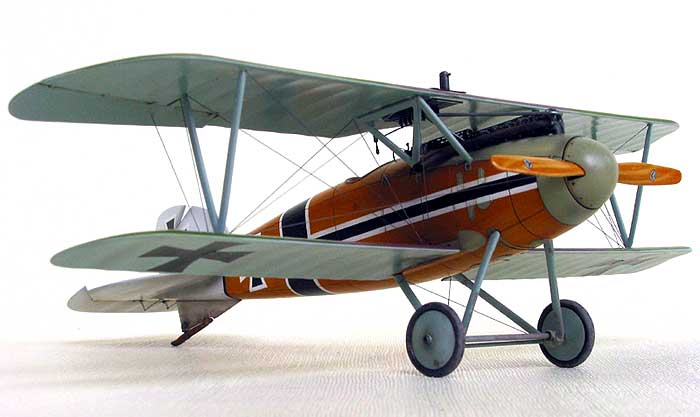
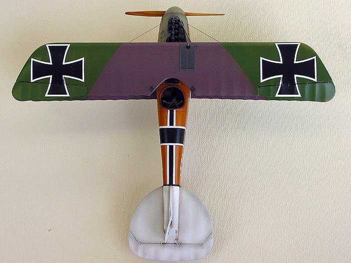
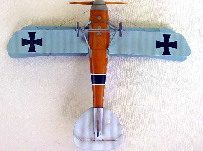
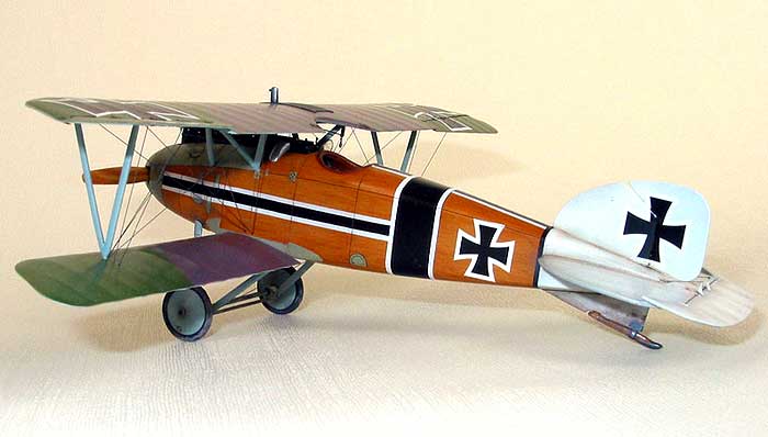
Albatros D.III
by
Tony Bell
|
|
|
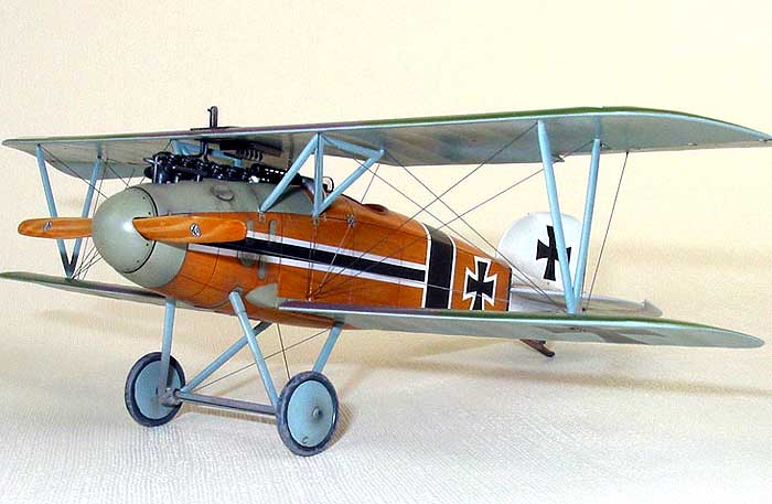
Albatros D.III |

Eduard's 1/48 scale Albatros D.III is
available online from Squadron
After the end of the “Fokker
Scourge” in late 1915 by the Allied DH.2’s and Nieuport 17’s, it wasn’t
until the Albatros fighters were introduced over the Western front in
mid-1916 that the Central Powers’ were able to re-established their
superiority in the air.
The D.III was introduced in
early 1917. In an attempt to improve manerverability, the D.III emulated
the sesqui-plane design of the Nieuport fighters with a lower wing that
was little more than half the area of the top wing. This had the desired
effect on performance, but unfortunately it also suffered from the same
structural limitations as the Nieuport. Due to their single spar design,
the lower wings were notoriously prone to twisting and separating in a
dive, resulting in catastrophic failure.
The Albatros D.V inherited
the same weakness, and it wasn’t until D.Va that the structural problems
were addressed. By the time of it’s introduction however, its performance
was no match for the Allied Spad XIII, Camel or SE5a. It wasn’t until the
Fokker D.VII came along that the Germans were able to field a fighter that
was demonstrably superior. By then of course, it was too late in the war.
The Kit
Having my interest in WWI
sparked by a fellow IPMS Toronto member, I decided to pick up the Eduard
Albatros D.III at a local show. I got the non-Profipack early version of
the D.III, featuring Manfred Von Richthofen’s machine on the box top. The
parts are moulded in a medium grey styrene, as opposed to the tan plastic
used for Eduard’s more recent releases. The parts breakdown is
conventional, featuring two fuselage halves, separate lower sesqui-wings
and a single piece upper wing. The surface detail is very crisp, and the
trailing edges of the wings are razor sharp. While the rib tapes are not
represented, the fabric effect on the wings and tail surfaces is nicely
restrained.
The decals are printed by
Aeromaster and are in perfect register. The white areas are a bit thick,
but very opaque.
I decided to pick up
Eduard’s photoetch set for the D.III, mainly for the Spandau’s cooling
jackets. The set also features replacement vents and hatches for the
fuselage, elevator control horns, radiators and radiator flaps, amongst
other details. The set is a significant improvement over an already nice
kit.
Both engine and cockpit have
to be assembled before closing the fuselage, so I decided to break with
tradition and start with…
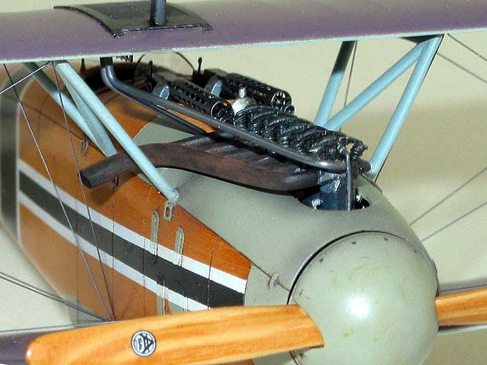
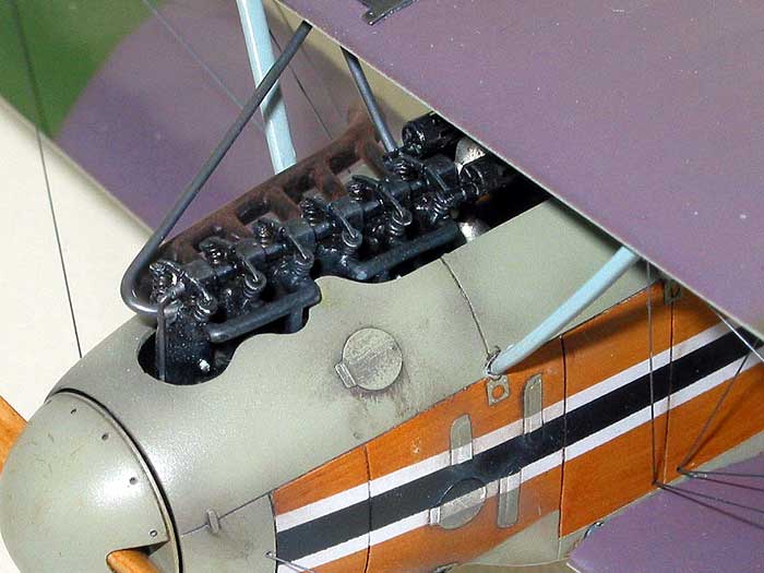
The Engine
The kit engine is a very
nice representation of the 160 hp Mercedes inline six. The only things
lacking are the rather prominent valve springs and rocker arms. Each
spring was fabricated from fine wire wrapped around a No. 75 drill bit.
They were cut to length, superglued to the engine and topped with disks of
sheet styrene punched with a Reheat Punch & Die set.
Click the thumbnails below to view larger
images:
The rocker arms were made
from 0.010” styrene strip. I also added spark plug wires, but would not do
so again, as they are completely invisible inside the fuselage.
The engine was airbrushed
Tamiya semi-gloss black, and then drybrushed with Humbrol Metalcote Steel.
The crank case (also totally obscured) was painted with Alclad II White
Aluminum.
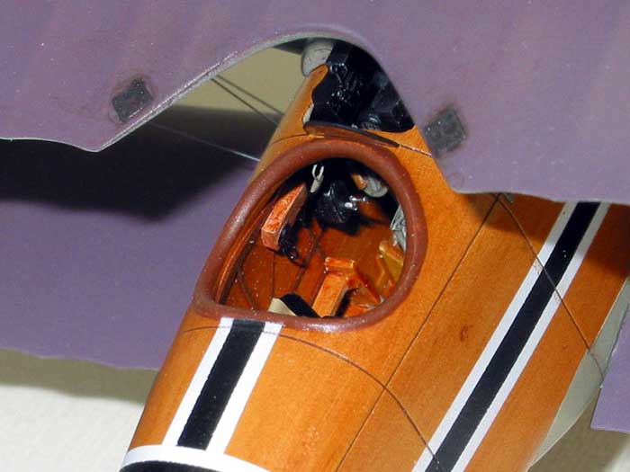
The Cockpit
After finishing the engine,
I turned my attention to the cockpit. This was a relatively risk-free area
to experiment with painting wood grain. I started by spraying the fuselage
interior with a 1:1 mix of Tamiya buff and white. Once this was dry, I
brush painted Windsor & Newton Raw Sienna artist’s oil all over the
interior, spreading it thinly and evenly. Too red. I wiped it all away
with paint thinner and tried again with Yellow Ochre. Too orange. I wiped
it clean again and tried a mix of Burnt Sienna, Yellow Ochre and Raw Umber
in an approximate ratio of 1:1:2. Aaah, that looked better.
Once I had brushed the paint
on thin enough to get the right colour density, I took a clean, absolutely
dry, paint brush and dragged it over the oil paint, leaving wood grain
streaks. I joggled (is that a real word?) the brush to give the grain a
bit of variation. As the brush picked up the paint, I wiped it off on a
clean, lint free cloth. Lint free is the key phrase, as any speck of lint
will glom (again, a real word?) onto the oil paint and mar the finish.
Once I was satisfied with the look of the wood grain, I set the pieces
aside for at least a week to dry, after which I sprayed on a coat of
Polyscale satin to protect the finish.
The other wood cockpit
pieces were painted the same way. Once all the wood was painted and
sealed, I brush painted the cockpit stringers with Testors burnt sienna
enamel.
The photoetch set offers a
replacement seat, but the real Albatros had a leather covered plywood
seat, which sheet brass was just too thin to represent. I opted to use the
kit seat, with a cushion cut from 0.020” sheet plastic. The whole seat was
roughed up with 120 grit sand paper and brushed with liquid cement to
simulate the leather texture and painted semi gloss black. The etched seat
harness was painted buff, suitably scrumpled and draped and attached with
white glue. The control column was dressed up with photoetch parts and
attached at a left bank, nose down angle. The rudder bar was also attached
at an offset angle.
Click the thumbnails below to view larger
images:
The sole instrument in the
Albatros cockpit is the tachometer. The kit supplies a blank face, and
there is nothing in the etched set. Having seen Mark Miller’s amazing 3D
computer renderings of the Albatros D.V on the World War I Modelling Page,
(
http://www.wwi-models.org/Images/Miller/render/Albatros/index.html ),
I emailed him and asked for the image that he used for the tach. He was
kind enough to send me the file, which I printed on my bubble jet and
photo reduced to scale. I then punched the gauge face out, attached it
with epoxy and finished it off with a Reheat instrument bezel.
The photoetch set also
offers various replacement switches and handles and whatnot which were all
used. The cockpit details were painted with black, silver and RLM02 grey.
The Fuselage
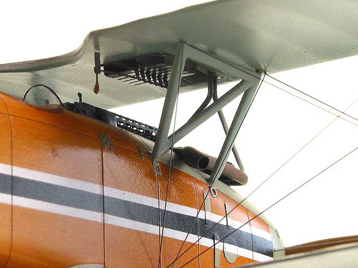
I decided to tackle the
Spandau machine guns first. The muzzles were drilled out and cut off, and
the cooling jackets were removed and discarded. The photoetch set provides
replacement cooling jackets which have to be formed into cylinders. This
was done by wrapping the etched pieces around an appropriately sized drill
bit. A section of hypodermic tubing was superglued inside the jacket along
the seam and attached to the kit plastic breech. The business end of the
cooling jacket was capped with the appropriate etched piece and the
plastic muzzle glued on. The etched set also provides cocking handles
which were superglued on.
The assembled guns were
first airbrushed with a satin blue-black mixed from Tamiya paints and then
heavily drybrushed with Humbrol Metalcote Gunmetal, followed by a lighter
drybrushing of Metalcote Steel. I then set guns aside until the fuselage
was finished.
On the real thing, the
spinner was slightly smaller in diameter than the fuselage, allowing the
edge of the cowling to be seen. I cut away the spinner backing portions of
the fuselage halves and thinned the edges down by scraping and sanding
them until they were acceptably sharp. The two rigging attachment points
at the root of each lower wing were drilled out with a No. 80 bit.
The cockpit and engine were
dry fitted and, much to my surprise, I found that there was no adjustment
necessary. The fuselage halves were joined with superglue, and the seams
were eliminated with a light sanding. The ventilation louvers, access
covers and foot step on the sides and bottom of the fuselage were scraped
and sanded away, as the photoetch set provides replacements. I cut the
rudder away from the vertical fin and attached it at an offset. The
horizontal stabilizer was glued to the fuselage to get it aligned properly
and once dry, the elevator was removed and repositioned. The etch set
provides the elevator control horns which were attached with superglue.
I decided to paint the
fuselage before attaching the wings in order to simplify the process.
After masking the engine and cockpit with tape and tissue paper, the sheet
metal portions of the forward fuselage were sprayed with Aeromaster enamel
RLM02 grey and masked off. The wood portion was painted as described above
and left to dry for a week, after which I sprayed on several coats of
Future to protect the finish.
The etched replacement
louvers and access covers were formed to the contours of the fuselage by
gently rolling an X-acto handle over them. They were painted RLM02 and
attached by brushing a dab of Future on the fuselage and positioning the
etched part, much like applying decals. Once in position, more Future was
brushed around the edges and allowed to dry.
The tail surfaces were
masked off and painted Tamiya flat white. The fuselage striping were then
masked and painted white, masked again and painted black. I then removed
all the masking and sprayed the whole fuselage with yet another coat of
Future. Finally I removed the cockpit and engine masking and brush painted
the coaming with Testors Leather enamel.
The Wings
The wings were prepared by
pre-drilling the holes for the rigging with a No. 80 bit in a pin vise.
The anchor holes in the top wing were drilled only part of the way through
whereas the holes in the lower wings went all the way through. The
radiator on the upper wing was scraped and sanded away in favour of the
etched replacement.
I cut the ailerons away from
the upper wing and reattached them to match the position of the control
column and the hinge straps replaced with 0.005” styrene strips.
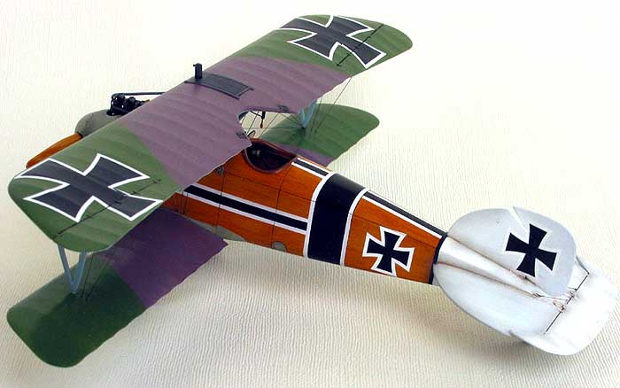
 The bottoms of the wings
were sprayed with Aeromaster enamel RLM65 lightened with white. For the
upper surface mauve I mixed Tamiya flat red, blue and white, while the
green was a mix of Polly Scale RLM83 Lichtgrun and RAF Slate Grey. The
colour mixing was totally unscientific, the paints being blended until
they simply “looked right.” The wings were sprayed with Future to prepare
them for the decals later on. The bottoms of the wings
were sprayed with Aeromaster enamel RLM65 lightened with white. For the
upper surface mauve I mixed Tamiya flat red, blue and white, while the
green was a mix of Polly Scale RLM83 Lichtgrun and RAF Slate Grey. The
colour mixing was totally unscientific, the paints being blended until
they simply “looked right.” The wings were sprayed with Future to prepare
them for the decals later on.
After painting, the
photoetched radiator parts were attached to the upper wing with contact
cement, and the radiator louvers glued in place with superglue. The louver
handle was built up with superglue and painted buff.
Assembly and Rigging
As is the case with Eduard’s
earlier kits, the locating holes for such things as the lower wings and
struts are really only dimples that need to be drilled out. I did so and
attached the cabane struts to the fuselage, using the upper wing to
position them properly. Once these were set, I attached the interplane
struts to the upper wing and attached the wing to the cabane struts. Once
this had set, I finally attached the lower wings to the fuselage and
interplane struts, letting the struts set the proper dihedral.
Then when I was handling the
model, I applied a leetle too much pressure and collapsed the
entire wing assembly.
After much swearing and
gnashing of teeth, I did what I should have done in the first place and
drilled out all the mounting points for the wings and struts and inserted
lengths of steel wire to hold it all in place. I went through the same
sequence all over again and was rewarded with a nice strong wing assembly.
The rigging was accomplished
with “invisible” nylon monofilament thread which was painted with Humbrol
Steel (can you tell I like this paint?). Several feet of thread were
painted all at once in order to provide ample rigging material. Each piece
of rigging was cut to about twice the required length and fixed in the
anchor hole in the top wing with superglue. Some holes were intended for
two pieces of rigging, so these were glued simultaneously. Working from
inboard to outboard, each piece of rigging was then pulled through it’s
proper lower hole, held tight and fixed in place with superglue applied
with a length of stretched sprue. A self-locking haemostat used to pull
the thread tight was an invaluable tool during this exercise. Once the
glue had set up, the excess rigging was carefully trimmed away with a
fresh scalpel blade and touched up with paint.
The rigging was completed by
attaching small lengths of painted thread to the elevator control horns.
Adding the Details
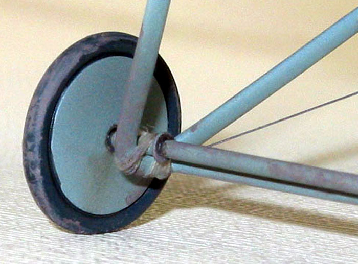
Having learned from my
earlier mistake when attaching the wings and struts, I drilled and pinned
the landing gear struts to the fuselage. The strut brace and axle were
replaced with brass tubing and styrene rod, respectively. This was done
simply because it was easier than cleaning up the kit parts rather than
for strength. Some cotton thread was de-fuzzed by passing it quickly over
a candle and wrapped around the axle and struts to simulate the bungee
cord shocks.
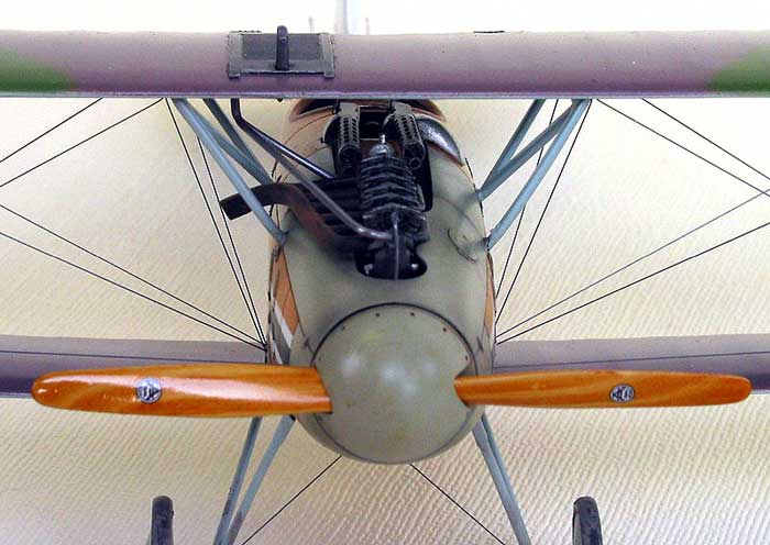
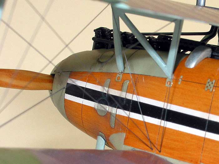
I painted the prop in a
similar manner to the other wood areas, and simulated the laminations by
removing more oil paint from the lighter areas with a fine brush slightly
moistened with thinner. The prop was given numerous coats of Future give
it a high gloss varnished look. The spinner was modified by drilling out
the fasteners around the circumference.
The open forward end of the
fuselage was filled with a black painted disk of sheet styrene set back
about 1mm from the forward edge. The prop and spinner were then glued to
this with a 0.030” styrene spacer.
The coolant pipes that run from the engine to the wing radiator were
fashioned from fine solder and attached with superglue. These were painted
steel in situ and buffed lightly.
The only decals used on this
model were the propeller logos and the national crosses on the wings,
fuselage and tail, for which I used the kit decals. It was when I was
applying the upper wing crosses that my second setback occurred.
The fuselage and tail
crosses went on fine, but I discovered that the kit decals just sneered at
Gunze Mr. Mark Softener and at Microset. The only thing these decals would
respond to was Solvaset so that’s what I used from the outset when
applying the crosses to the wings. The first decal went on just fine. By
luck, I managed to position it exactly right off the backing paper and did
not have to slide it into position. The second decal didn’t go so well.
It’s initial position was a bit off, but when I tried to prod it into the
right place I discovered that the Solvaset had softened the Future and
effectively turned it into contact cement! I tried to lift the decal off,
but only succeeded in mangling the decal and ruining the paint finish.
More swearing and gnashing of teeth!
I let the now-wrecked area
of the wing re-harden whereupon I sanded it down and repainted the green.
When I reapplied the Future something strange happened and it went all
fish-eyed and horribly uneven. Even more swearing and gnashing of teeth,
but with a much heavier emphasis on the swearing! Out came the sandpaper
again. And the green. And the Future. This time I cut it with a bit of
Tamiya thinner and it sprayed beautifully. I managed to beg a friend for a
replacement decal and finally applied it properly, using the Solvaset only
on top of the decal.
The canvas and metal
surfaces of the airplane were sprayed with a 60/40 mixture of Poly Scale
flat and satin to give it a slight sheen.
Weathering was kept light
and consisted of an artist’s oils wash mixed from Burnt Umber, Lamp Black
and Titanium White. A similar brownish grey was mixed from Tamiya paints
and sprayed heavily thinned in various areas to reproduce general grime.
Finally the mud on the tires was made from ground pastel chalks mixed with
water and applied with a Q-tip (cotton bud).
The exhaust was painted flat
black and dusted with brown and orange chalk pastel powder.
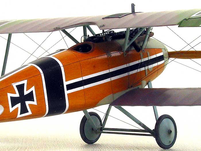
As my first ever attempt at
a WWI subject this was a definite learning experience. Rigging and wood
graining in particular required techniques that I had never tried before.
The Eduard Albatros was the
perfect kit in this circumstance, being both well engineered and nicely
detailed without being overly complicated (imagine a Bristol Fighter or
Fe.2b as a first crack at a WWI model!).
It may have been my first,
but it won’t be my last.
Click the
thumbnails below to view larger images:
Model, Images and Text Copyright ©
2003 by Tony Bell
Page Created 04 March, 2003
Last Updated
17 March, 2004
Back to
HyperScale Main Page |
 Home |
What's New |
Features |
Gallery |
Reviews |
Reference |
Forum |
Search
Home |
What's New |
Features |
Gallery |
Reviews |
Reference |
Forum |
Search