|
Classic Airframes' 1/48
scale
GAF Canberra Mk.20
Part One - Construction
by Brett Green
|
 |
|
GAF Canberra Mk.20 |

Classic
Airframes' 1/48 scale Canberra will be available online from Squadron
For a
detailed examination
of the contents of Classic Airframes' 1/48 scale Canberra, see the
in-box review elsewhere on HyperScale.
It was a pleasant surprise to see the Australia Post
courier pull up outside our house on a Saturday afternoon in early April. I have only
ever seen these couriers working on weekends on the two Saturdays
leading up to Christmas so it was completely unexpected.
When I saw that the contents of the box was Classic Airframes'
new Canberra, it
seemed to be further evidence that Christmas had come very early.
We had a busy day that Saturday but I dropped everything on Sunday and
got cracking, first photographing sprues for the review, then preparing
resin and plastic parts and, at last, assembling.
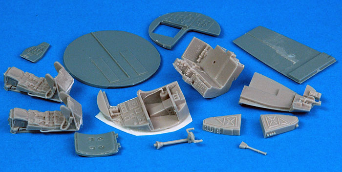
Parts Preparation
I was lucky enough to receive some of the earliest sprue
shots for this kit. The plain USPS box contained grey styrene, resin,
clear canopy parts and decals. Instructions and one set of
clear parts (with wing tip and landing lights) were not available at
this early stage. Even so, these minor omissions were not going to stop
me from building this kit straight away.
The absence of instructions meant that I spent a little
more time than usual familiarising myself with the plastic and resin
parts.
I started by cutting off all the plastic parts and
cleaning up the sprue connector points. This proved to be a very fast
task as there are only 42 parts, although some of these are very large!
Next, I took to the resin parts. Some of the casting
blocks are quite stout, so this time I decided to use a grinder
attachment in my Dremel motor tool for this task. I ran an extension
cord outside, brought along a container of water to keep the resin parts
wet (to reduce dust), donned a respirator mask and started work.
Properly prepared and with this power tool, the casting blocks were off
in no time at all. Even with the resin parts damped down, however, there
is a lot of flying resin dust so, if you plan to use a motor tool for
this job, I strongly recommend that you do so outside and wearing some
form of face mask.
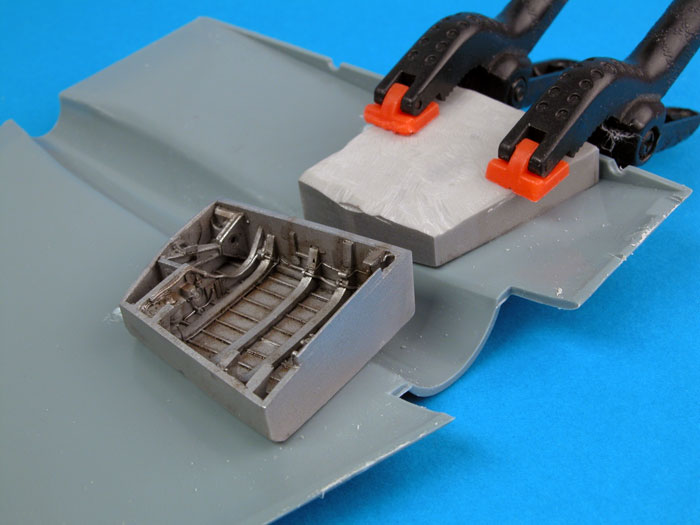
Wings
Construction started with the wings, as the resin gear bays are one of the more
challenging areas that I like to work on early.
Once the excess resin is removed from the top of the
resin gear bays, they fit inside the thick Canberra wings without
further preparation.
Trailing edges looked a little thick so I scraped the
insides and gave them a sanding before assembling the wings. The big
wing halves mated up quite well considering the absence of locating
aids. I had a little overhang (top wing over bottom wing "overbite") on
one wing, but it was easily sanded to shape. I sanded the trailing edges
again after assembly to improve the appearance of this area.
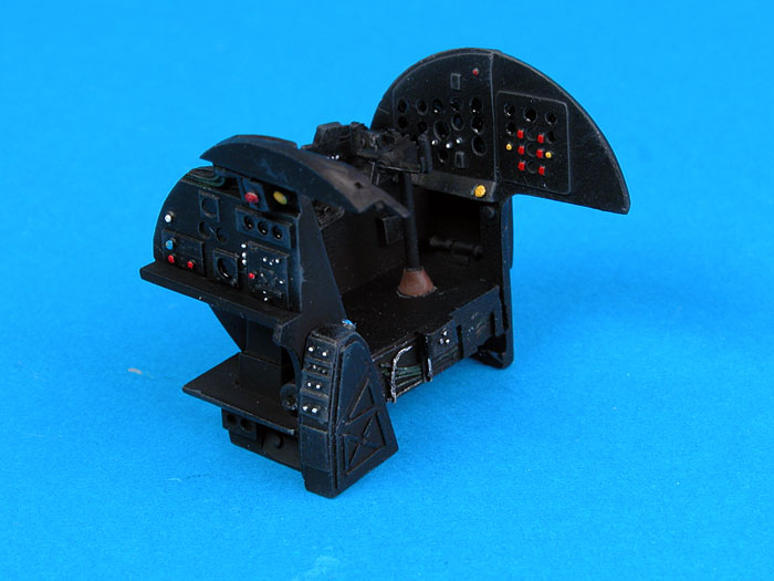
Cockpit
Next was the cockpit. This is made up of a well-detailed jumble of resin
and plastic parts, including two ejector seats. I checked some of my own
reference photos to confirm locations of bulkheads and details, as kit
instructions were not included with this early test shot. The angled
front of the rearward-facing navigator's position was quite rough where
I had ground off excess resin, so I covered the scarred surface with
thin plastic sheet.
The interior parts received a coat of Tamiya Flat Black,
followed by some restrained dry brushing with dark grey and medium grey.
Details were picked out in white, yellow and red paint. Instrument
lenses were filled in with semi-gloss black. The navigator's station is
a real work of art in resin, but the position is so well hidden that I
decided not to install the seat here. I still painted up the instruments
though - at least we can see it in the photos! The seats are beautifully
detailed, by the way, with harnesses and oxygen hoses cast in place. The
resin control yoke is a delicate jewel too.
Click the
thumbnails below to view larger images:
|
|
|
|
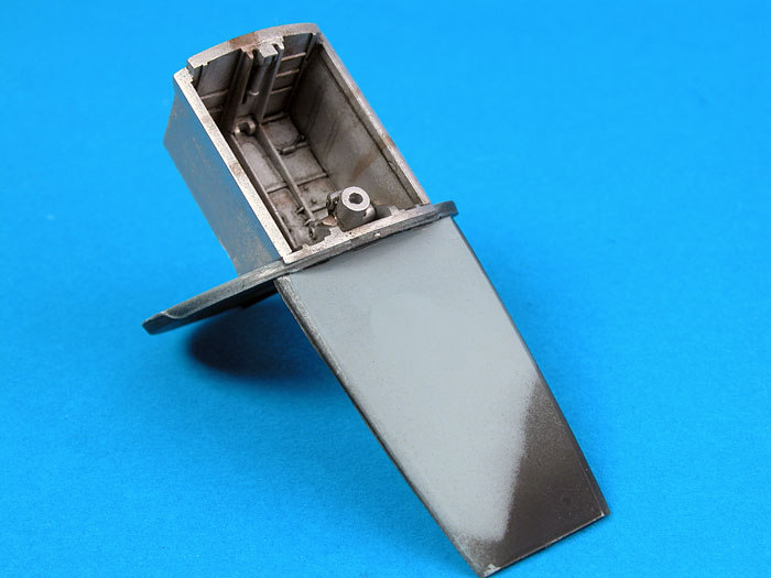
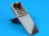
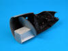
The resin forward wheel well features gorgeous detail. This part is glued to the rear cockpit bulkhead and the main cockpit floor.
|
|
|
|
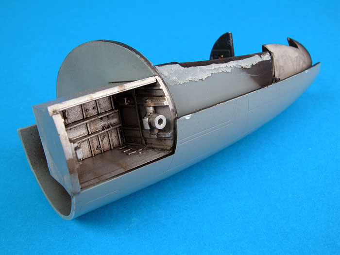
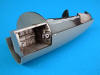
After painting and several rounds of test-fitting, the cockpit components are installed in the port side nose half.
|
|
|
|
The floor had to be reduced in width to permit the two halves of the nose to fit without gaps.
|
|
|
Fuselage and Airframe Assembly
With all the cockpit elements prepared and painted, I
found the best place to start assembly was the rear bulkhead.This is
glued to the forward wheel well, which sets the angle perfectly.
I then
glued the cockpit floor to the front bottom lip of the rear bulkhead.
This wheel well / bulkhead / floor assembly was glued to the port
sidewall. Now, the pilot's position was slid, without glue, into the
opening under the instrument panel. I test fitted the instrument panel
bulkhead on the sidewall and, when I was happy with the position, I
simply ran liquid glue along the join on the sidewall. There was still a
little play in the resin pilot's position, allowing the bottom to be
carefully lifted with a toothpick. A spot of super glue was applied
under this part to secure the resin to the floor. The last major cockpit
component was the bomb aimer's position in the tip of the nose. This was
glued to the floor and the port sidewall. The remaining cockpit parts -
control column, pump handle etc - were installed at this stage.
Test fitting showed that the cockpit floor was a bit too wide to permit
the forward fuselage halves to meet, so the side of the floor was
thinned and trimmed until a gap-free result was possible. This is not
difficult, just an exercise in trimming, sanding, test-fitting and
repeating until the nose halves fit properly.
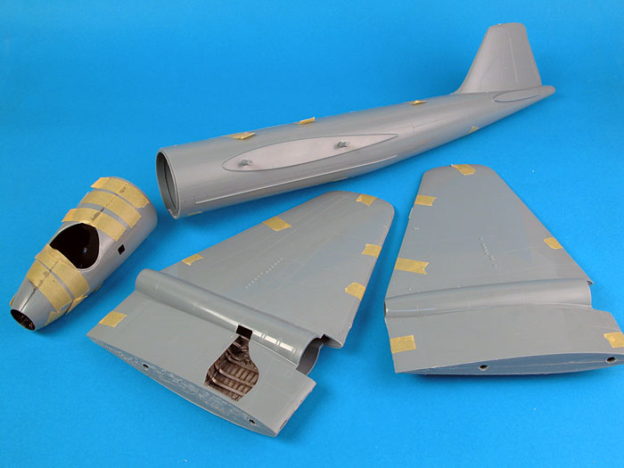
The long main fuselage halves came next. I test-fitted the halves and
the fit looked so good that I decided to apply liquid glue along the top
seams there and then. The fit of these big chunks of plastic is perfect
with no additional work after cleanup.
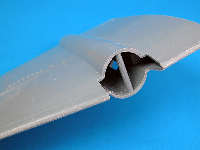
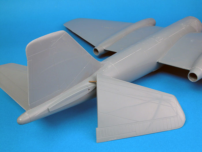
The engine nacelles will also fit well after a bit of trimming and
sanding of the intakes and the leading edge of the wings. Once again,
patience will be rewarded with a gap-free and (almost) step free result.
I found that there would be a step where one intake met the wing
nacelle, so I used a short length of sprue as a spreader. This
eliminated the step prior to assembly.
Click the
thumbnails below to view larger images:
The leading edges of the wing were sanded to blend in
the "shoulders" of the intake inserts, the result being no gaps and no
steps.
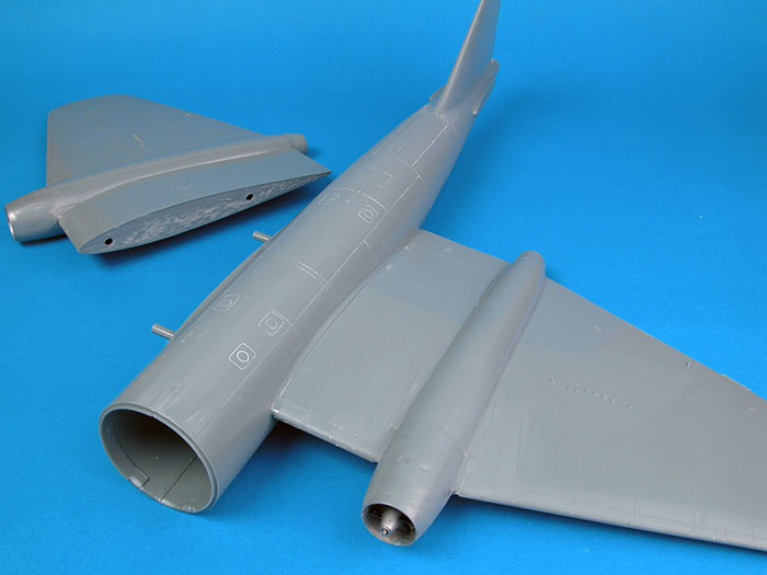
Classic Airframes supplies two wing spar rods to secure the big wings to
the fuselage. The holes for the spars in both the wings and the fuselage
were partially flashed over, so I reamed them out with a rat-tail file.
I also sanded the mating surfaces of the wings to ensure that they sat
flat against the fuselage. I fed the spars through the fuselage and
attached the wings to either end using super glue, effectively tacking
them in place. Tamiya Extra Thin Liquid Cement was then flowed into the
upper and lower seams at the wing root. The fit was once again very
good, with almost no gaps and absolutely no steps on the upper surface,
and only narrow and very manageable gaps on the lower joins.
At this stage, the angled horizontal tail surfaces were assembled. Holes
were drilled for brass rod spars, and these were also secured to the
fuselage using super glue. Tamiya Liquid Cement finished the job once
the correct dihedral was set. There is a small gap at the top and bottom
of the stabilisers, but these will be quickly despatched with a line of
Gunze Mr Surfacer.
So far so good. Now for the most important join on the model - the nose
to the main fuselage. Comparing these parts showed a slightly different
cross-section on each mating face. The sides of the nose section were
slightly "bulged" compared to the main fuselage. This would result in an
unsightly step without remedial action. I would rather do almost
anything other than filling and sanding, so I took some preventative
measures. I installed a spreader bar from plastic sprue in the front of
the main fuselage section. I trimmed the piece of sprue until the
cross-sections of the nose and the main fuselage matched.
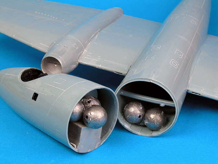
The undercarriage of the Canberra sits quite a long way forward, so I
installed lead weights in the rear of the nose (behind the rear
bulkhead) and in the forward fuselage. Even so, these five large lead
weights will not be enough to keep this big model on its nose gear.
I marked datum points on the middle top of the nose and the fuselage,
then applied a spot of super glue on each inside lip of the kit nose. I
slid the nose section onto the fuselage and applied a spot of
accelerator to tack the assemblies in the correct position. A final
stronger bond was achieved using liquid glue along the join line.
Despite my preparations I still I wound up with a slight step at the
bottom of the port side. This step was bridged with Milliput and sanded flat. Panel line detail
was
restored before painting.
Next time I will probably glue each front nose half to
each main fuselage half before installing the cockpit components and
joining the fuselage halves. By using this method, it should be possible to
perfectly align the nose and fuselage parts.
After assembly, I found that I had enough room to
install another three weights in the Navigator's position behind the
pilot. Lucky I did not install that ejection seat earlier! I painted the
large weights flat black before gluing them into place. Finally, there
was enough weight to keep the nose down.
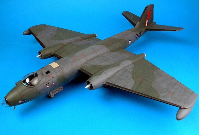
In little more than ten hours, I have the basic airframe of this
classic British bomber completed.
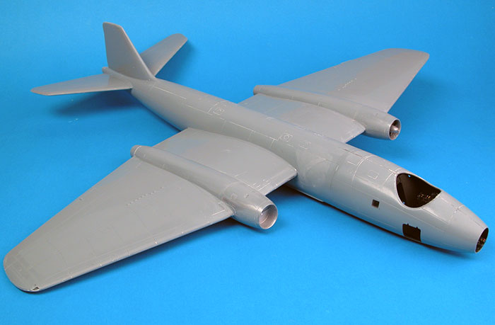
My impressions at this stage are pleasant surprise and satisfaction,
both at the model's large size, and also due to the speed of assembly.
The fit is generally sweet too, assuming parts are properly prepared and
some time is taken to test fit and trim in the areas I have mentioned
above.
Continued in Part Two
Model,
Images & Text Copyright © 2006 by
Brett Green
Page Created 04 April, 2006
Last Updated
02 May, 2006
Back to
HyperScale Main Page |
 Home
| What's New |
Features |
Gallery |
Reviews |
Reference |
Forum |
Search
Home
| What's New |
Features |
Gallery |
Reviews |
Reference |
Forum |
Search