|
Classic Airframes' 1/48
scale
Canberra T.17
by Brett Green
|
 |
|
English Electric Canberra T.17 |

Classic
Airframes' 1/48 scale Canberra T.17 is available online from Squadron
For a
detailed examination
of the contents of Classic Airframes' 1/48 scale Canberra T.17, see the
in-box review elsewhere on HyperScale.
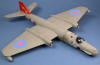
The English Electric Canberra was a groundbreaking
aircraft when it entered service in the early 1950s. The Canberra set
and held many altitude, distance and speed records in its early years.
In addition to widespread and long service with the Royal Air Force, the
English Electric Canberra was exported to many countries including
Australia, New Zealand, Sweden, France, West Germany, India, Pakistan,
Rhodesia, Ethiopia, Argentina, Chile, Ecuador, Peru and Venezuela.
The Canberra's service record was remarkable in its longevity, spanning
from the Suez crisis to Vietnam to the Persian Gulf. In fact, the final
Canberra PR.9s in RAF service are only due to retire this year.
The Canberra T.17 was a specialized Electronic Counter
Measures/Electronic Warfare variant converted from the B.2 bomber. 22 of
these aircraft were produced specifically for a joint RAF/RN unit, 360
Sqn. The bomb bay and the newly designed nose housed the additional ECM/ECW
equipment. The Canberra T.17 had retired from service by the mid-1990s.
Classic Airframes' 1/48 scale Canberra T.17 kit shares much in common
with the earlier B.2 and TT.18 releases, but includes a new forward
fuselage with the unique nose and an additional 20 resin parts. The
complete kit comprises 42 parts in grey styrene; 41 parts in grey
colored resin; 11 clear injection molded parts; instructions; plus a
decal sheet and painting guide for two aircraft.
Not surprisingly, construction was very similar to
Classic Airframes' Canberra B.2 (finished
as a GAF Canberra Mk.20) that I built earlier this year. This time,
however, I did manage to avoid a few problems by applying the lessons
that I learnt the first time around.
Parts Preparation
I started by cutting off all the plastic parts and
cleaning up the sprue connector points. This did not take long as there are only 42 parts, although some of these are very large!
Next, I took to the resin casting
blocks with my Dremel motor tool fitted with a grinder bit. I ran an extension
cord outside, brought along a container of water to keep the resin parts
wet (to reduce dust), donned a respirator mask and started work.
Properly prepared and with this power tool, the casting blocks were off
in no time at all. Even with the resin parts damped down, however, there
is a lot of flying resin dust so, if you plan to use a motor tool for
this job, I strongly recommend that you do so outside and wearing some
form of face mask.
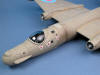
Cockpit and Fuselage
Before starting the cockpit, I glued the port-side
fuselage half to the port-side nose; and the starboard-side fuselage
half to the starboard side nose. The result was two complete fuselage
halves, perfectly aligned where the nose meets the main fuselage part
with no gaps or steps whatsoever.
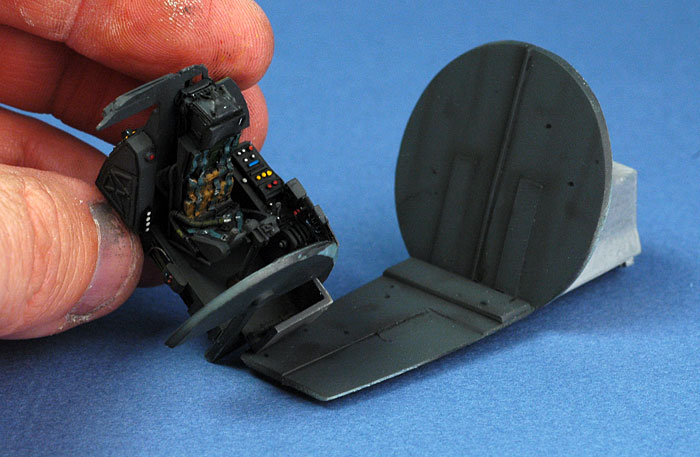
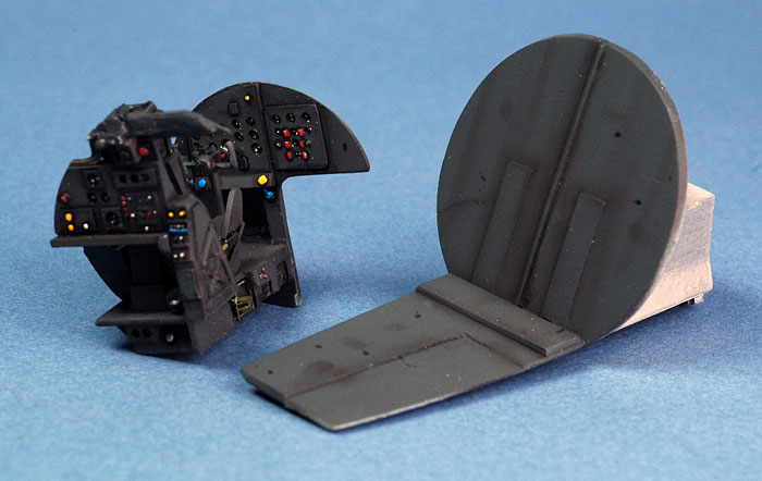
Next was the cockpit. This is made up of a well-detailed
jumble of resin and plastic parts, including two ejector seats.
 The interior parts received a coat of Tamiya German Grey
(acting as "scale black"),
followed by streaking and staining. This was achieved with a thin mix of
Tamiya Flat Black and Red Brown applied with the Testor Aztek airbrush
fitted with the fine (tan coloured) tip. Structural details and natural
shadow areas were then further deepened with a selectively applied black
oil wash. The interior parts received a coat of Tamiya German Grey
(acting as "scale black"),
followed by streaking and staining. This was achieved with a thin mix of
Tamiya Flat Black and Red Brown applied with the Testor Aztek airbrush
fitted with the fine (tan coloured) tip. Structural details and natural
shadow areas were then further deepened with a selectively applied black
oil wash.
Details on the instrument panels and side consoles were picked out in white, yellow and red paint. Instrument
lenses were filled in with semi-gloss black and dial detail added using
white paint applied with a sharpened toothpick. I
decided not to install the navigator's Martin-Baker ejection seat just
in case I needed to add extra nose weight later.
I then glued the cockpit floor to the front bottom lip
of the rear bulkhead. This wheel well / bulkhead / floor assembly was
glued to the port sidewall. Now, the pilot's position was slid, without
glue, into the opening under the instrument panel. I test fitted the
instrument panel bulkhead on the sidewall and, when I was happy with the
position, I simply ran liquid glue along the join on the sidewall.
Test fitting showed that the cockpit floor was a bit too wide to permit
the forward fuselage halves to meet, so the side of the floor was
thinned and trimmed until a gap-free result was possible. This is not
difficult, just an exercise in trimming, sanding, test-fitting and
repeating until the fuselage halves met along the centreline.
Click the
thumbnails below to view larger images:
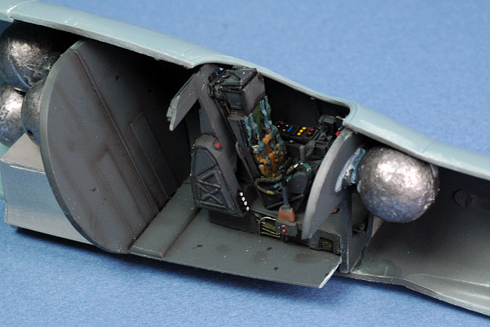
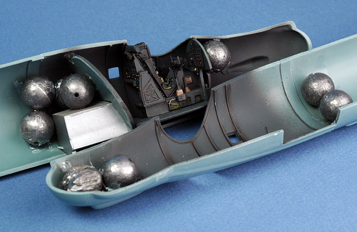
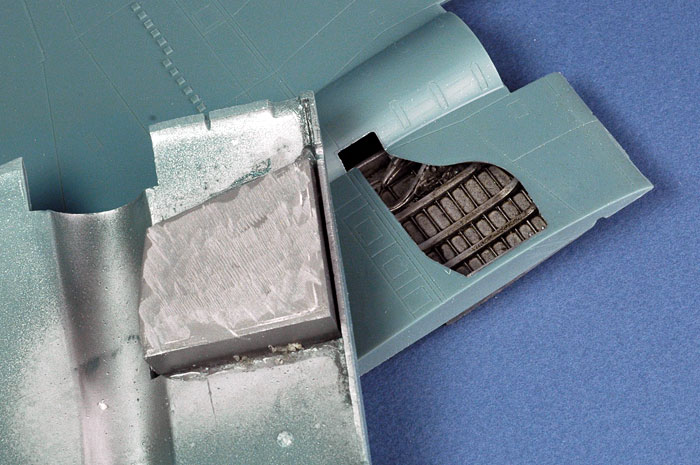
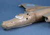
One of the blessings of that bulbous nose is the
additional space available for nose weight. I thought I had plenty of
weight in the front of my first Canberra, but in the end it was not
enough. I would not make the same mistake this time. I super-glued nine
big lead fishing sinkers into the fuselage - three in the nose and six
behind the rear cockpit bulkhead. This proved to be adequate.
With the cockpit, nose gear and lead weights installed,
the fuselage halves were brought together.
Wings and Tailplanes
Once the excess resin was removed from the top of the
resin gear bays, they fitted inside the thick Canberra wings without
further preparation.
Trailing edges looked a little thick so I scraped the
insides and gave them a sanding before assembling the wings. The big
wing halves mated up quite well considering the absence of locating
aids. I had a little overhang (top wing over bottom wing "overbite") on
one wing, but it was easily sanded to shape. I sanded the trailing edges
again after assembly to improve the appearance of this area.
I glued the bottom intake half to each wing, then glued
the top half in place. In retrospect, I realised I would have been better
off gluing the top half to the top wing first. Some trimming and
shimming was required to get the intakes to fit properly, but this extra
effort meant that very little filler was needed once the parts
were glued in place.
Classic Airframes supplies two plastic wing spar rods to secure the big wings to
the fuselage. The holes for the spars in both the wings and the fuselage
were partially flashed over, so I reamed them out with a sharp hobby
knife.
The top of the wing joining surface was sanded to remove a slight ridge.
This added a valuable extra degree or so of dihedral.
I replaced the plastic spars with brass tube. The spars were
passed through the fuselage and
attached to the wings to either end using super glue, effectively tacking
them in place. Tamiya Extra Thin Liquid Cement was then flowed into the
upper and lower seams at the wing root. The fit was once again very
good, with almost no gaps and absolutely no steps on the upper surface,
and only narrow gaps at the lower joins.
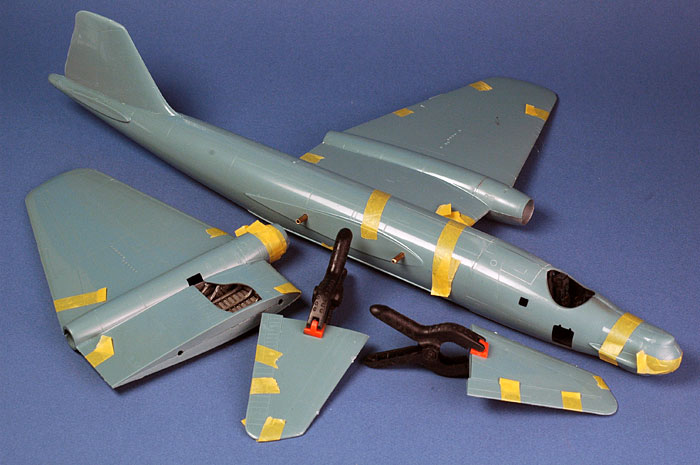
At this stage, the angled horizontal tail surfaces were assembled. Holes
were drilled for brass rod spars, and these were also secured to the
fuselage using super glue. Tamiya Liquid Cement finished the job once
the correct dihedral was set.
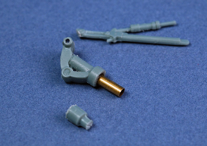
While the glue on the main airframe set, I modified the
nose gear strut. Without modification, the nose gear sits too high,
giving the front of the Canberra a slightly stalky appearance. I cut off the
top of the gear leg above the oleo collar (about 3/8" of leg plus
the locating pin), and sliced off the retraction strut. The top of the
remaining nose gear was drilled out and a short length of brass tube was
inserted as a replacement locating pin.
I also cut off the locating pins for the wheels and
drilled out holes for replacement brass pins.
The fit of the new resin fuselage tail cone proved to be
slightly tricky. First, I managed to glue the part on crooked. I cut the
rear of the resin part off and re-glued it at the correct angle. There
was also a fairly large gap between the top of the resin part and the
bottom of the fin. This was filled with Milliput, and sanded to shape
when the two-part epoxy putty had cured.
A few places on the airframe required putty, including
the upper fuselage seam and the front of the nose; a step on one side of
each engine intake; and the engine tail cones. Before painting, the wing
tip tanks were assembled and installed, and the canopy was masked and
glued to the fuselage. All the remaining dangly bits would be installed
at the last moment.
Before painting, I drilled out locating holes for the
various antennae and masts. I also drilled out three holes around each
jet intake to depict the starter cartidge vents. The holes were filled
with Krystal Kleer, resulting in a recessed circle - a close enough
representation for my purposes. The sundry resin scoops and vents on the
lower fuselage were installed at this stage too.
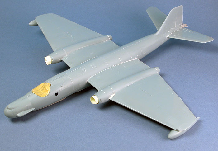
The assembled model was sprayed with an overall coat of
Tamiya Grey Primer straight from the can. This highlighted a few lumpy
areas that needed a bit more attention with the sanding stick.
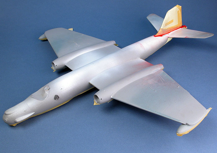
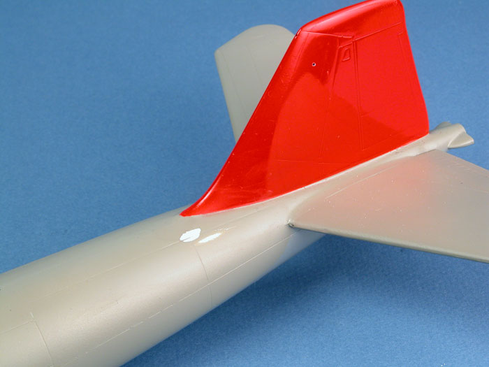
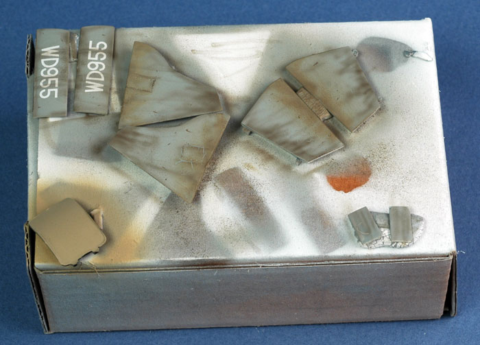
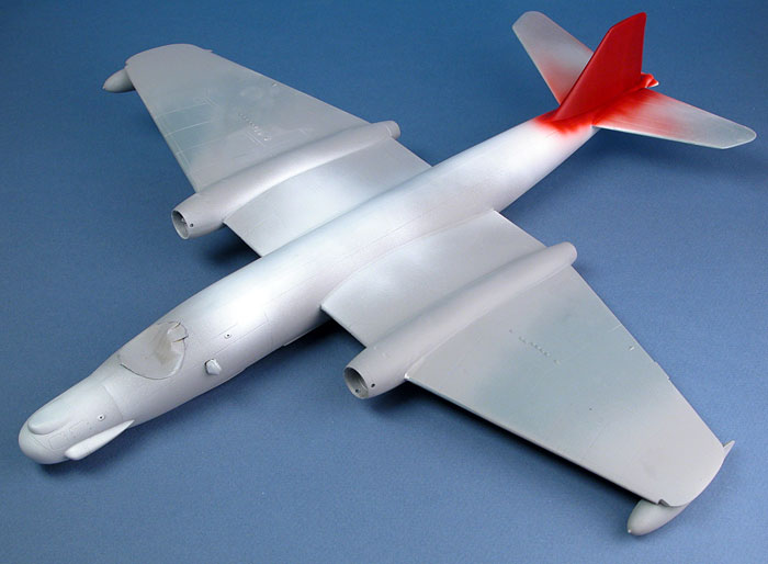
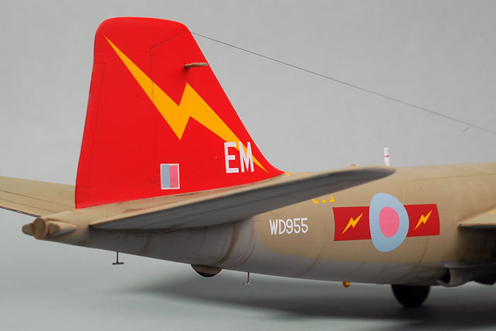
Next, these repaired areas and the entire tail were
covered with Tamiya's Fine White Primer, also from the spray can. Red is
notoriously difficult to spray, and I wanted a nice even coat of white
underneath to ensure even coverage.
Despite this careful preparation, the red acrylic paint on the
tail cracked and crazed. There was no alternative but to sand the tail
back to its white undercoat. Once this messy task was complete I
repainted the tail, this time using lacquer spray paint (Tamiya TS-49
Bright Red) decanted into the paint cup of my Aztek airbrush. This
delivered a high gloss, even finish. The only problem was that it was
not the same shade of red as the Squadron flashes on the kit decals. Ah
well, can't have everything...
Click the
thumbnails below to view larger images:
|
|
|
|
|
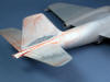
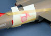
The red paint crazed, so the tail was sanded back to the white primer |
|
|
|
|
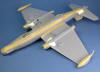
With the repairs made and the top colour sprayed, the airframe was masked for the lower surface colour. |
|
|
|
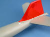
More woes - I damaged the camouf;age paint in front of the fin, requiring more repairs. |
|
|
The lower surface now received a coat of Tamiya AS-2 Light Grey IJN.
This seemed to be a reasonable match for RAF Light Aircraft Grey. The
fast, smooth finish straight from Tamiya cans is a real Godsend on the
these big models.
The camouflage demarcation lines on the lower fuselage and engine
nacelles were masked with Tamiya tape, then Gunze acrylic H336 Hemp was
applied as the upper surface camouflage. Gunze paints are usually quite
glossy when dry, but this colour was dead flat.
The two rectangles above the navigator's position were masked and
sprayed black to represent windows. The larger rectangle slightly aft -
a dielectric antenna panel - was painted Tamiya XF-55 Deck Tan. At this
time I also painted the bases of the aerial masts black and re-masked
the canopy to spray the white line of sealing tape.
The entire airframe now received a coat of Future floor polish to
provide a glossy surface for decals. During spraying, a thick glob of
Future ran down
the rear fuselage. I stupidly wiped the area with a cloth dampened in
Windex, and promptly stripped the paint in the area. More running
repairs...
Classic Airframes' decals performed beautifully over the
glossy surface of the model.
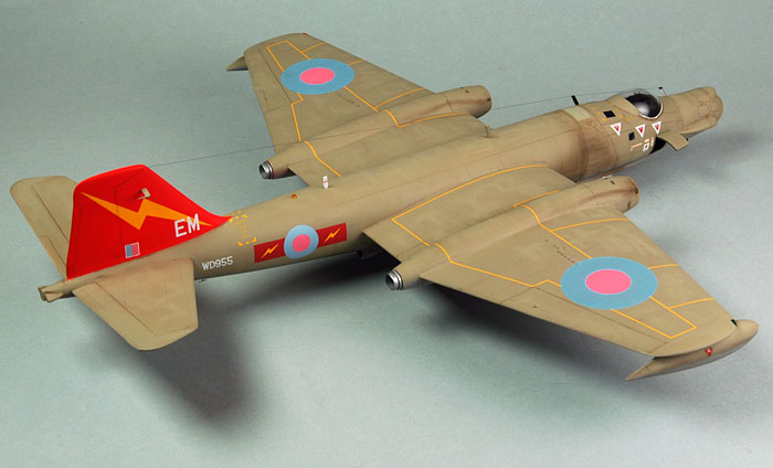
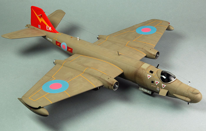
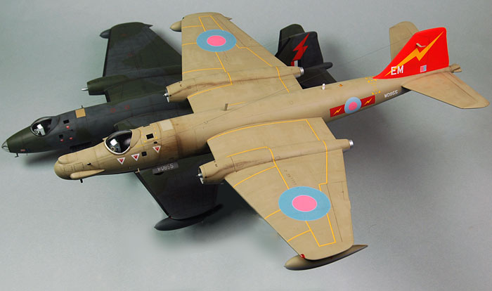
The yellow wing walkway lines were time consuming to cut
to shape and position on the model, but I love the way they break up the
broad surfaces of the wings.
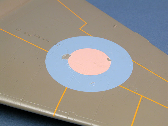
Once all the decals were down, I applied Micro Sol. To
my horror, the upper wing decals crazed quite noticeably when the Micro
Sol had dried. I brushed a coat of Solvaset over the top to see if this
would settle the crazing, but it had no effect. In desperation, I
finally brushed Mr Mark Softer (no, it is not a typo, that really is
the product's name) onto the two decals. This stuff is really aggressive
and, as I should have guessed, it actually melted a few spots into the
decals.
I had little choice other than to sand the decals back
as far as possible without damaging the surrounding camouflage, and
re-paint the markings.
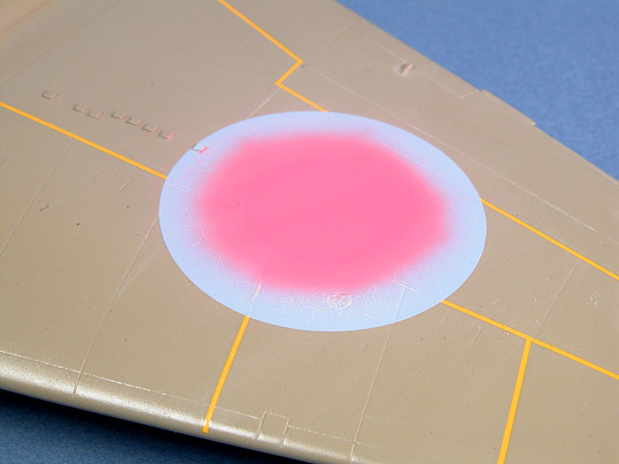
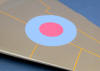
As it turned out this was not entirely a bad thing as
the pink in the kit decals is a bit insipid. I mixed up a brighter batch
of pink using Tamiya acrylic Red and White. This was sprayed onto the
centre of the upper wing roundels. While I was at it, for the sake of
consistency, I resprayed the pink on the fuselage roundels and fin flash
too.
Click the
thumbnails below to view larger images:
|
|

|
|
First, a custom mix of RAF Roundel Pink was sprayed onto the centre of the roundels. |
|
|
|
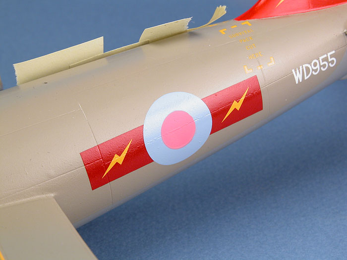
The pink section of the fuselage roundels were also resprayed. |
|
|
|
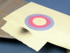
|
Masks were cut from Post-It Notes using an Olfa Circle Cutter. |
|
|
|
Extreme decal repair - the new blue and pink roundels. |
|
|
Weathering
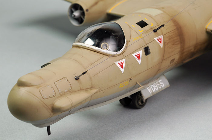
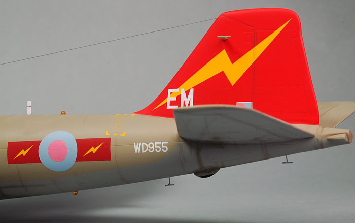
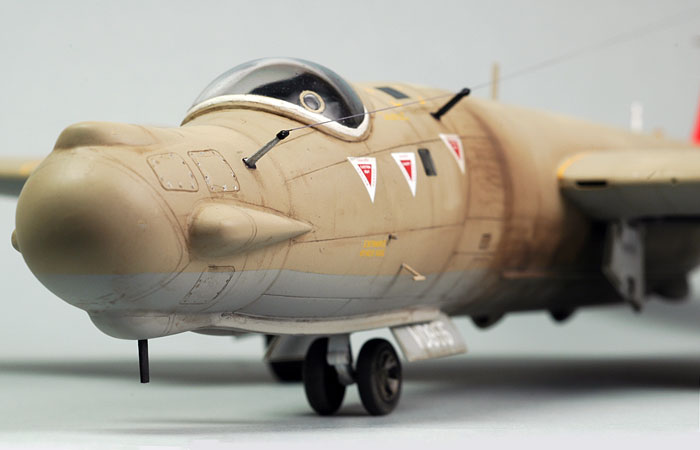
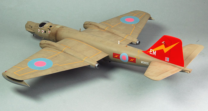
While searching for reference on the Internet, I was
fortunate to find a
great photo of this specific aircraft, serial WD955, on airliners.net.
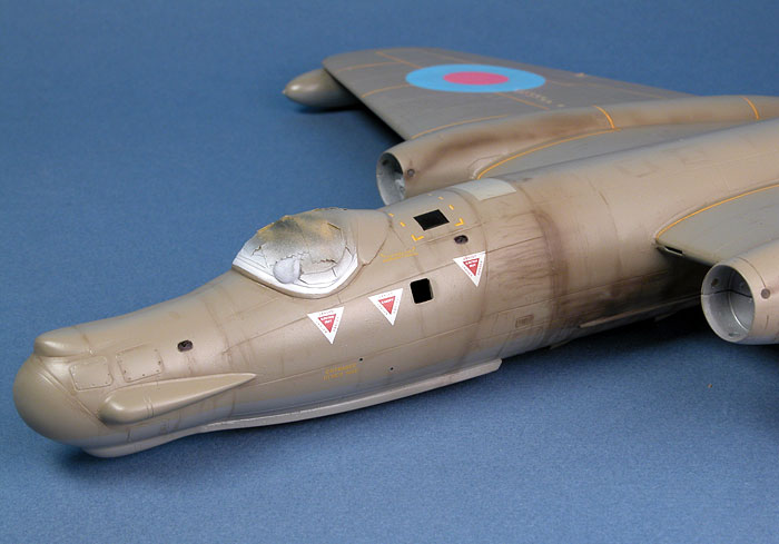
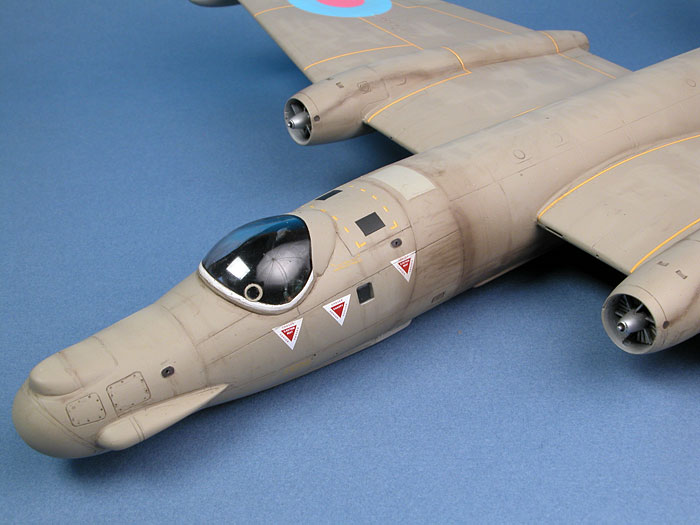
The photograph showed a peculiar pattern of heavy
weathering on the fuselage aft of the cockpit and on the lower fuselage.
My best guess is that smoke from the inboard starter cartridges created
the heavy staining (maybe mixed with dirt and condensation on the
surface), while the bottom of the wing and the open inner gear doors
generated a mild venturi effect, funneling the filth along the lower
fuselage. There is also an obvious stain running along the engine
nacelle from the starter cartridge vent.
I filled the airbrush paint cup with a very thin mix of
Tamiya Flat Black and Red Brown, carefully building up fine lines of
this dirty mix to duplicate the pattern of weathering in the reference
photo. I also added some heavy weathering on the bottom of the fuselage
and underneath the wings, especially between the engine nacelles. More
streaking was added below the tail surfaces and, ever so lightly, on
selected panels around the nose. The same mix was used to create some
random streaks and spots on the wings and fuselage. Panel lines on the
nose and the engine nacelles, plus control surface hinge lines, were
subtly emphasized with a thin wash of Tamiya Semi-Gloss Black acrylic
applied with a fine brush.
I wanted to avoid geometrically dividing the wing by
highlighting panel lines. I felt that this would be unrealistic, and
would also distract from the distinctive yellow wing walks. Even
so, I needed to do something to break up that vast expanse of
Hemp. I decided to try something different. After spraying a couple of
coats of Polly Scale Flat over the completed paint job, I applied a
mottle of Gunze Hemp over the top. This mottle was fractionally paler
than the varnished paint of the same colour, and also had a very
slightly different gloss level. I was pretty satisfied with the result.
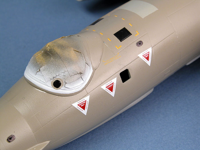
The final step of weathering was to add a few tiny
"chips" around the fasteners on various nose panels using a silver
artist's pencil.
Click the
thumbnails below to view larger images:
|
|
|
|
The distinctive weathering pattern is first sprayed onto the forward fuselage and engine nacelles. |
|
|
|
The addition of some subtle panel highlighting and a flat coat makes a big difference to the effect. |
|
|
|
Weathering is now almost complete. |
|
|
|
|
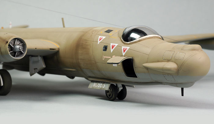
The undercarriage was assembled and secured to the model
at this time. I was pleased to find that the shortened nose gear
leg greatly improved the sit of the model. Now it hunches down
authentically over its nose gear.
Various antenna masts and aerials were painted and glued
in place. I installed a few extra devices that I found in reference
photos, although they were not mentioned in the instructions. These
included two fine "T" aerials underneath the fuselage fabricated from
fine copper wire; and two blade antennas - one under the forward nose
and one on top of the rear fuselage. These were sourced from spare
antennas included in the Classic Airframes kit. The reference photo of
WD955 also seemed to show a pitot tube on the side of the forward
fuselage. I robbed a pitot from an old Hobbycraft Bf 109 kit for this
job.
Finally, the photo suggested that this aircraft was
fitted with "disco lights" - rotating orange beacons above and below the
rear fuselage. I chucked a short length of Cutting Edge clear orange rod
in my Dremel Motor Tool and shaped the top into a dome using
progressively finer grades of sanding sticks. When I was satisfied with
the basic shape, I cut the light off to an appropriate height and dipped
the part in Future for a brilliant shine. This process was repeated for
the second light.
Click the
thumbnails below to view larger images:
The final job was rigging the antenna wire from my
pre-drilled hole at the top of the fin to the two aerial posts on the
port side of the forward fuselage. E-Z Line was used for this job. The
more I use this elastic rigging, the more I like it!
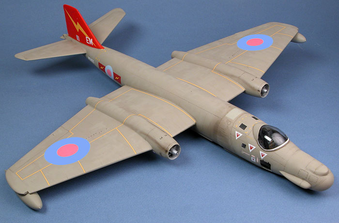
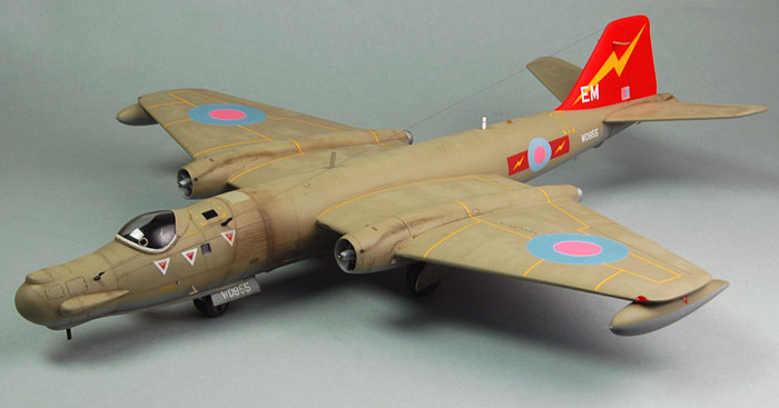
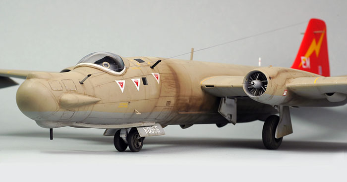
Classic Airframes' brand new 1/48
scale Canberra T.17 was a lot of fun to build.
Detail is impressive, construction is
challenging in places but was never frustrating, and this late version
certainly presents a different facade compared to the earlier B.2 and
TT.18 kits. When confronted with a photo of my
model, a friend of mine declared that the aircraft looked like a "wart
nosed witch". I actually think it looks pretty attractive, but
even if you don't agree, you can't say it is not interesting!
This is the fifth Classic
Airframes kit I have built so far this year, and the second Canberra. I
will be grabbing a third Canberra to build some time in the future too
(I want to have one in silver with the white upper fuselage).
If you don't mind a bit of parts
preparation and can anticipate problems before you commit to glue, you
should have few problems building any of Classic Airframes' 1/48 scale
Canberra family.
Thanks to Classic Airframes for the
sample.
Click the thumbnails below to view larger images:
Model,
Images & Text Copyright © 2006 by
Brett Green
Page Created 24 September, 2006
Last Updated
21 February, 2007
Back to
HyperScale Main Page |
 Home
| What's New |
Features |
Gallery |
Reviews |
Reference |
Forum |
Search
Home
| What's New |
Features |
Gallery |
Reviews |
Reference |
Forum |
Search