|
Special Hobby's 1/72 scale
Junkers Ju 388L
by
Jan Forsgren
|
 |
|
Junkers Ju 388L |

HyperScale is proudly supported by Squadron.com
Background
The Junkers Ju 388 appeared in the last
months of the war as the ultimate operative
variant of the Ju 88 family. The path from the 88 to the 388 was not
straight and easy but long and complex.
The ancestor to the 388, the Ju 188, was developed
from the Ju 88B in the end of 1939 but did not reach operational status
until the beginning of 1943 after the usual political hassle.
In 1942 the Ju 88A-0 was tested with a machine gun
arrangement in a rear turret, and towards the end of 1943 this concept
would be ready for operational aircraft. Also in 1942 RLM realized that
the available night fighters Bf 110G and Ju 88C needed a replacement as
development would stop when production would switch over to the Me 410
Zerstörer and Ju 188 light bomber. Work on a pressurized crew
cockpit was also progressing at this time.
In 1943 Junkers proposed a second generation of Ju
188, the J (night fighter), K (bomber) and L (reconnaissance), but RLM
regarded this development so extensive a new designation was necessary:
the Ju 388. The Hubertus Programme was born.
This new generation incorporated a remotely
controlled rear turret, a pressurized cabin with a streamlined canopy,
fuselage, wings and tail plane from the Ju 188 and more powerful
engines. The engine installation was unified for the different power
plants, the radial BMW 801TJ, and the Jumo 222F and 213E, so that
aircraft production could be suited to the available engines.
In April 1944 the purpose built prototypes rolled
off the line, V1 to V6 for Ju 388J/K/L. Also included in the development
work were the ten first assembled Ju 188S-0 and T-0. A number of Ju
388L-1 is supposed to have reached front line service and there are
photos of several operational aircraft parked on the ground.
The kit
Right after my scratch
built Ju 388J V-2 (a feature found here
http://hsfeatures.com/features04/ju388v2jf_1.htm) was finished
Special Hobby released their version, and also the K and L variant. Of
course I had to buy and evaluate the kit. I eventually bought three, two
V-2 and one K/L.
The night fighter
variant has the solid nose, the smaller canopy and belly gun pack
whereas the K/L has a large vacuform canopy in two pieces and the wooden
bomb bay that on the reconnaissance (L) was used for extra fuel and
cameras.
Looking at the instructions everything looks easy.
The injection parts are delicately engraved, the styrene is light gray
and easy to work with, not brittle at all. The yellow resin is of the
smelly kind, probably very dangerous, and of course easy to break. At
least one cockpit side panel broke easily. There is also a small photo
etched fret with delicate wing antennas, rudder pedals, a Peilgerät
antenna and a few more nice things.
Easy to assemble? No, not at all.
No separate part whatsoever has any definite
locating pin or anything else to connect other parts to. You will get my
point as I describe the assembly process. I understand this was one of
Special Hobby’s first complete kits and it is like a “Special Edition”
with all multimedia parts, but one could at least demand the styrene
bits to go together in a better way. I picked up a more recent kit from
SH, a Bv 155, and it is up to injection kit standards.
Cockpit and fuselage
There are some fit issues for the resin cockpit
which comes in two pieces, floor and left hand side and a separate right
hand side. After dry fitting I painted all cockpit interior black RLM 66
(dark grey, almost black) together with the separate resin seats.
The resin interior for the tail wheel was painted
in a gray green color, darker than RLM 02 and glued to one fuselage
half; I would later spray RLM 02 (X201) in the wheel bay.
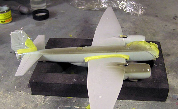
I assembled the fuselage halves without any problem
as I usually remove all tabs to sand the halves flush anyway. The
fuselage came together quite easily with the tail wheel bay inside, only
some minor work with Milliput and rescribing of panel lines after
sanding the seams. The wooden bomb bay is a one-piece item which fit
very well on the lower fuselage.
After that the cockpit walls and floor was glued
with CA (remember to ventilate your workshop while working with CA and
resin, I use my spray booth). I used a black thin wash for the cockpit
interior and when dry I dry brushed all edges and knobs light gray. The
seats had integrated seat belts; the seats were painted black 66,
cushions blue and belts silver gray, and all was dry brushed and laid
aside until it was time to finish the cockpit at a later stage.
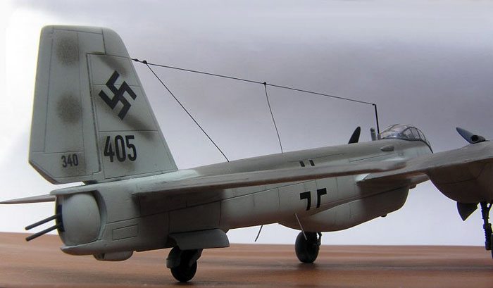
At the rear of the empennage the resin turret was
glued with a slight gap to the rear end, and finally the upper part
holding the turret. I sanded this part flush with the empennage but I
later saw that this item does not conform to the tapering rear end in
plan view; the whole piece is equally wide.
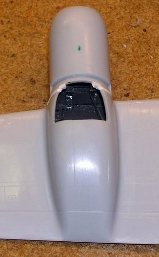
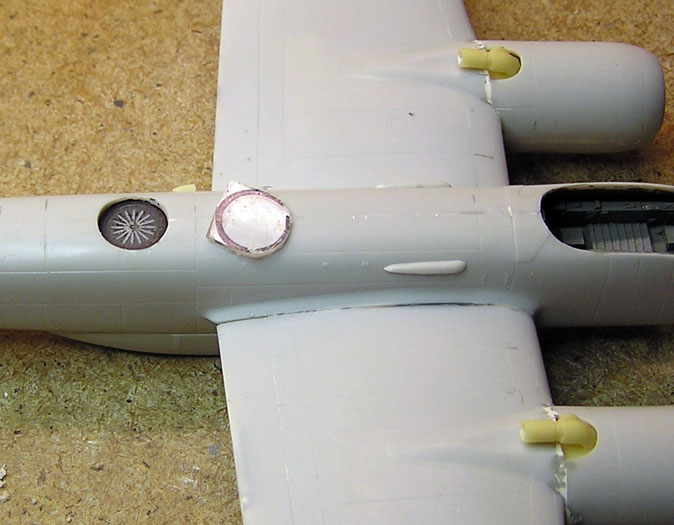
The Peilgerät antenna was located under a
Plexiglas (Perspex) window on the top fuselage. The antenna was
painted silver with a black wash. The kit has no solution as how to fix
the antenna to the fuselage, there is only a round kit part to hold the
PE antenna but no clear styrene. I cut a hole on top of the fuselage
halves, larger than the glass opening and used a piece of sheet styrene
fixed to a piece of sprue glued to the bottom inside of the fuselage.
I cut a piece of clear plastic from an old music
cassette box, thick enough to manage the curvature of the upper fuselage
and glued it in the fuselage. When dry it was sanded flush with the
fuselage surface with ever finer sand paper, and polished until it
looked like Perspex.
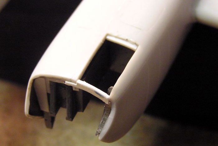
Wings and engines
The location of the resin bottom of the gear bay
was somewhat vague but it was likely to be parallel to the inside of the
upper wing surface. Plastic card and a piece of sprue were used. The
resin was painted like the tail wheel well interior.
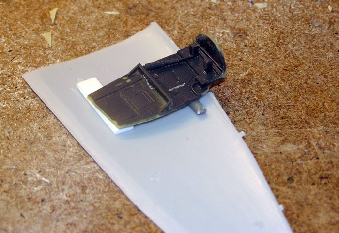
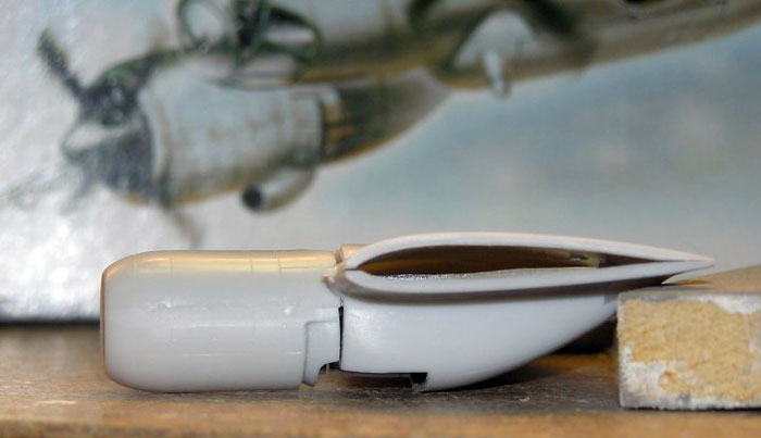
That done it was obvious there was a problem
joining the engine with the gear bay. It seems the gear bay is too large
in side view compared to the engine; this will be more apparent when the
bay doors are installed in the open position. It was also necessary to
use styrene shims in order to position the engine in the correct axial
position.
Click the thumbnails below to
view larger images:
All four wing halves were sanded thin in the
trailing end, as much as possible, and the wings were glued together.
The wings had a good surface detail and were straight as they should be
on the Ju 388. The landing light was made from a piece of sprue with a
small hole drilled in the back end filled with silver paint. A cutout
was made in the wing and the glass piece installed and sanded flush.
This is an easy way to achieve an acceptable landing light. There are
more complicated and better methods.
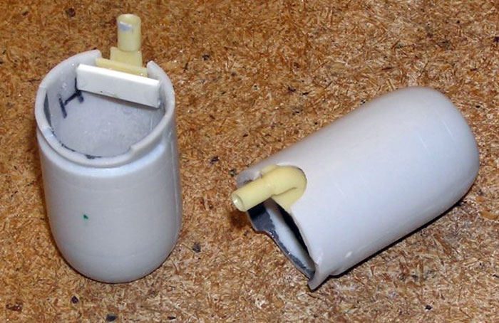
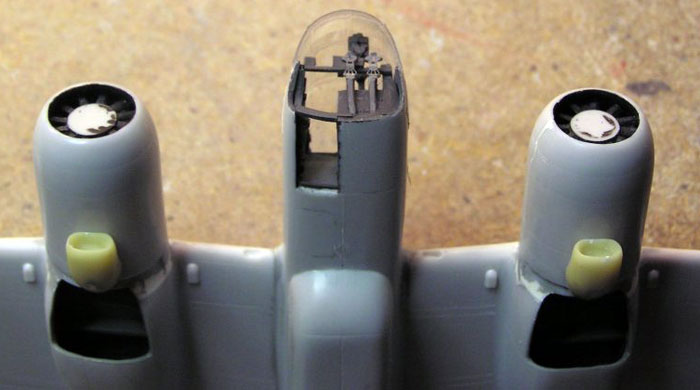
The resin radiator and the fan were assembled and
were to be installed inside the engine shell. This sounds easy but it
was really a tricky operation! There is nothing to position them
against, the inside is cone shaped and the fan blades had to be cut to
fit this cone.
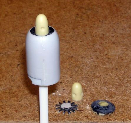
The fan was glued to the radiator part; both were
painted and installed into the engines which had black painted insides.
After some trial and errors both engines looked good.
In the rear of the engines are the exhaust gas
outlet pipes, quite naturally! The exhausts are collected and after
driving a turbo supercharger they are expelled through large pipes on
top of the wings, together with a small pipe for the engine compartment
ventilation. They are in resin and delicate, but nothing to glue them
to, you have heard that before! This was not so difficult to do but the
opening had to be enlarged and it’s always best to thin down the edge of
everything that will be seen, as the edge of the opening.
I decided to fit the engines to the wings before
mating the wings to the fuselage, something I almost never do as it’s
almost impossible to align the engines correctly, but I thought it would
be easier to work with the engine/wing joint this way. The result was
almost perfect in the end. Because of the bad fit between engines and
wheel bays more work with styrene had to be done.
Click the thumbnails below to
view larger images:
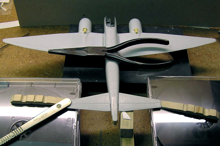
Main assembly
The wing did not have any locating tabs at all
connecting to the fuselage, they were just hollow ends. I drilled holes
for brass tubes in the fuselage, tubes that could be made to fit inside
the wings. The wing surface connecting to the fuselage was sanded until
the dihedral was correct, but then they did not match the wing root of
fuselage side. After the wings were glued in place with epoxy glue in
the wing/tube joint and liquid poly for wing/fuselage I had to use
Milliput to build up the lower wing root to match the wing.
For the stabilators I drilled a hole for a 1/16”
piano wire and used epoxy glue so there was time to adjust the
stabilators in the correct position.
The inlets for the turbochargers on the lower side
of the engines are in resin and fit well, remember not to take away what
looks to be excess resin on its rear, as it fits behind the engine
cooling air flaps.
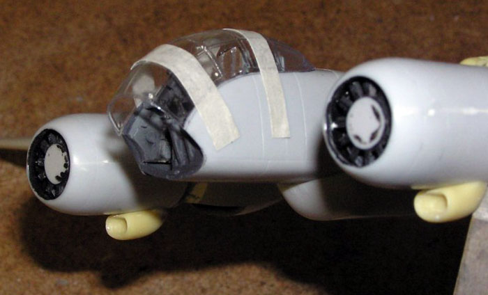
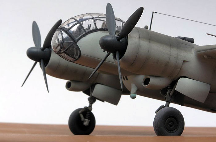
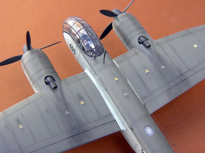
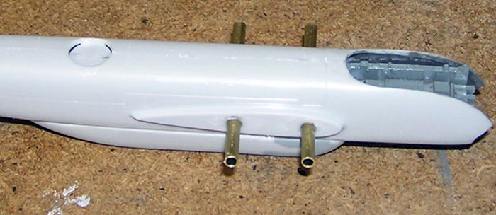
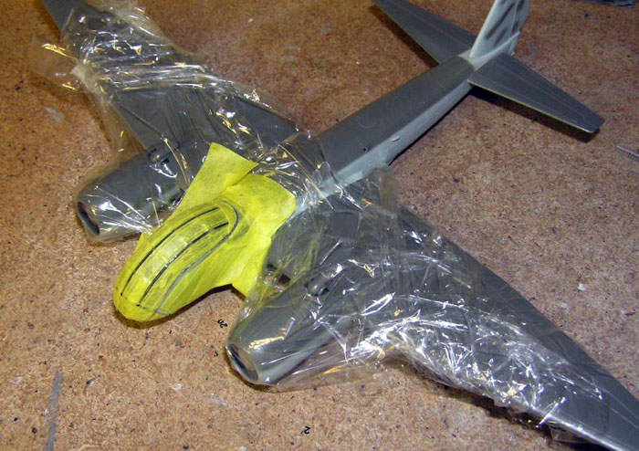
Canopy
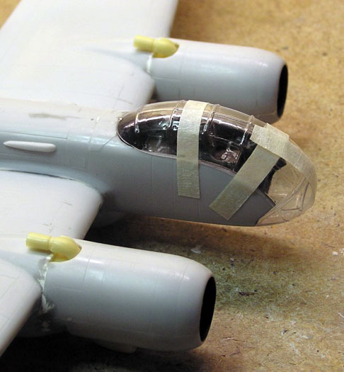
The canopy is a very nice vacuform in an upper and
a smaller lower piece. The framing is slightly raised and there are some
circular indentations that can be mistaken as flaws but which really are
to be there!
The upper part is wider than the fuselage but that
can be overcome by letting it rest on the outside of the fuselage, this
can be seen on the photos. The lower part had to be trimmed to fit the
lower window cutouts. I had to add a supporting frame and a ledge in the
rear to hold this part.
Click the thumbnails below to
view larger images:
Now it’s time to add the seats, the PE pedals,
control stick and the instrument panel to the cockpit. The instrument
panel sits on a rod between the side panels and being in resin this is
fragile, be careful.
Everything that is visible from outside must be
painted RLM 66 before the large canopy can be mounted to the cockpit,
that’s easy to forget and this canopy is large. The canopy was polished
and I saw no need to dip it into Future as I used epoxy glue carefully
applied along the fuselage edge. The upper part was mounted first, but
only after hours of trimming and test fitting of both parts.
After the epoxy cured the lower part was attached;
this was more difficult as there was no ledge to hold it in the correct
position, only very careful use of tape. I managed to avoid getting
epoxy glue where it shouldn’t be and I’m very pleased with my first
two-part vacuform canopy. I had to use Milliput around the lower windows
but apart from that the fuselage/canopy joint looks good all around.
Click the thumbnails below to
view larger images:
The resin periscope needed some trimming before
attaching on upper and lower fuselage behind the canopy.
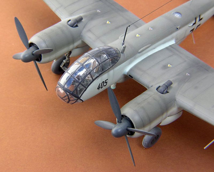
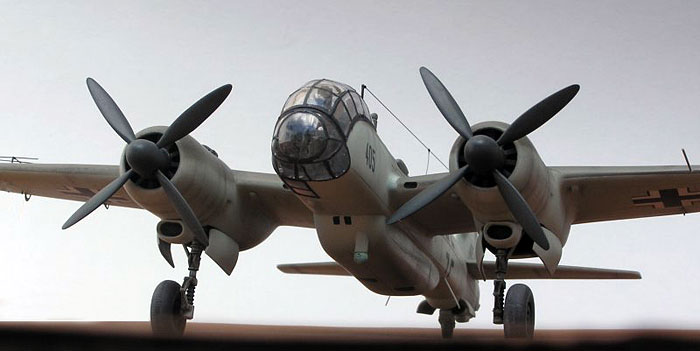
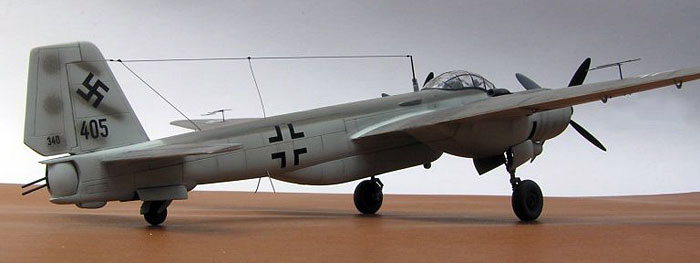
Painting
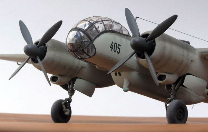
I intended to use the kit decals for the machine
found in a building with lots of destroyed aircraft at the war’s end in
Leipzig-Mockau, no. 405 painted RLM 76 with top of wings and fuselage in
what the kit instructions and the AJ-Press book say is RLM 81, and a few
blotches of 81 on the fin and rudder.
The Ju 388L that was taken to the US after the war
seems to have been in a splinter camouflage (RLM 81/82?), so why this
batch of L-1 almost flight ready aircraft should be in RLM 81 beats me.
In the photo of the operational aircraft it may as well be a splinter
camouflage being shown. Maybe the destroyed aircraft were in RLM 81 and
were to have been painted in a splinter pattern with 82 before
delivery?
I also decided to represent no. 405 after an
intense period of service with some delicate weathering.
The few trouble areas, engine/wing joint and
wing/fuselage joint were treated carefully, panel lines were rescribed
where necessary and the entire model was sanded with #1200 wet sand
paper.
The whole model was painted with Xtracolor
Lichtblau (X208), lower areas masked and top side painted
Braunviolett (X210).
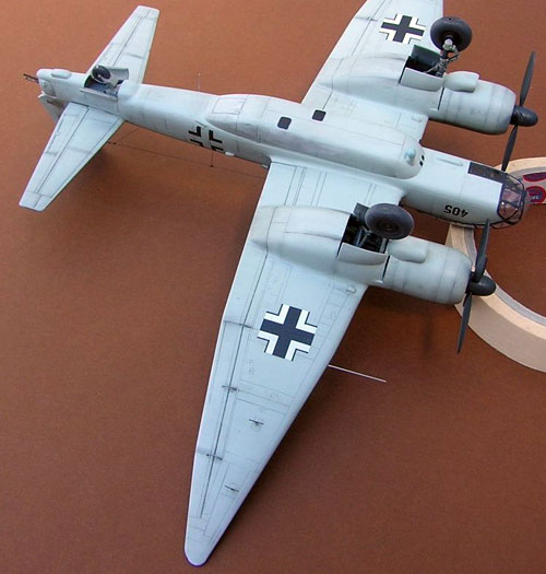
When painting, I usually use the gear bay doors as
masks for the gear bays. It’s quite simple to use a blob of Blu-Tac and
squeeze the doors to the closed position, and they will be painted as a
benefit.
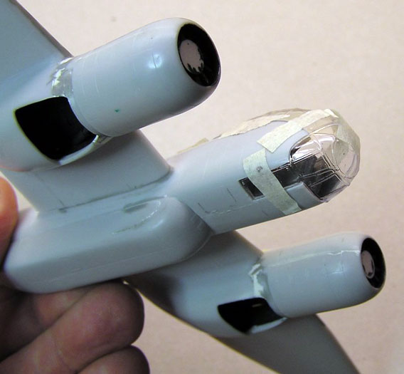
I masked the canopy for painting the frame in RLM
66, a mix of Tamiya black and white, first in one direction then the
other.
Removing the tape all looked beautiful, and the
whole canopy was masked with tape and Micro Mask for the remaining paint
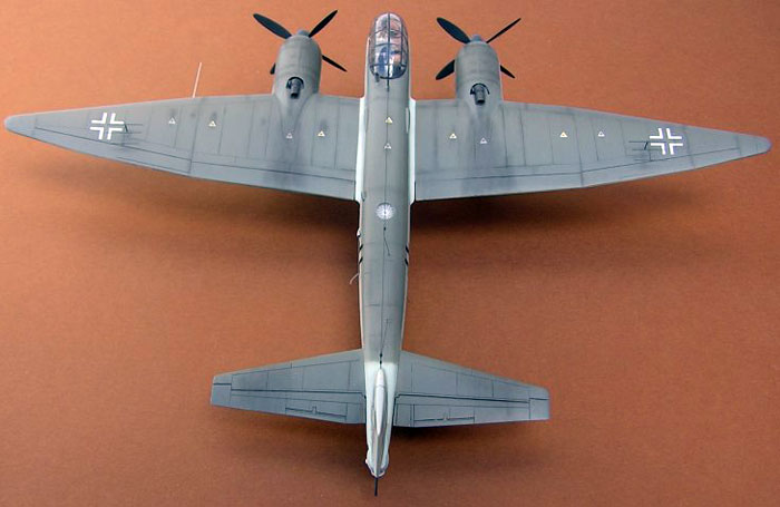
work. The decals went on, old Superscale crosses and the numbers and
letters were the kit decals.
I always airbrush the whole airframe with several
layers of Future (wet paper sanding in between) before applying a wash
of brown and black oil color and white spirit, as I find Future more
resistant than enamel to white spirit.
Click the thumbnails below to
view larger images:
The wash is then wiped off in the air flow
direction, more thoroughly on the upper than the lower side. To seal the
wash I apply Future with Tamiya Flat Base, this is also the base for the
dry pastels that add further weathering on some panels and areas.
The exhaust pipes were painted with a mix of
Humbrol Metalcotes to a burnt metal look.
Many of the small injection parts are very crudely
reproduced and almost impossible to use. The main gear and tail wheel
were replaced with Italeri Ju 88C-6 counterparts, and some trimming had
to be done to make the main gear fit the resin blocks of the gear bay
interior. The tail wheel needed even more surgery to fit, but in the end
all looked fine painted RLM 02 and with a black wash. Main wheels are
kit items painted dark grey.
The resin spinners are of mixed quality. They seem
to be of the correct shape but a real problem is that the holes for the
four propeller blades are not in line! If you are aware of it easy to
see on the finished model as I did not try that much to correct it. The
propeller blades are injection molded and look fine but slightly crude
so careful sanding is needed before assembly. The spinner and propeller
blades were painted RLM 70 (X204).
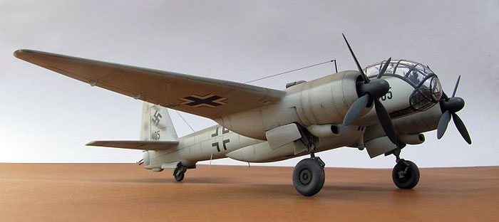
The resin barrels for the belly gun pack and the
turret were replaced with small brass tubes that were attached after
being painted dark metal.
Antennas were made from stretched sprue: the left
wing under side have two FuG 101 radio altimeter antennas. The lower
fuselage has the FuG 25 IFF antenna and the FuG 10p trailing antenna for
HF radio.
The ultimate detail is so fragile it’s almost
impossible to handle: the wing mounted FuG 217R antennas which are
included in the brass PE sheet. I added a round piece of thin styrene on
the wing, painted the antennas dark green and attached first the PE pole
to the round bases and then the antennas. With a pair of tweezers I
arranged the antennas symmetrically and sloping down in the rear like
I’ve seen on a photo. These antennas are definitely likely to be
destroyed sooner or later!
At this stage I removed the canopy masking,
and…disaster! The Micro Mask lifted most of the Tamiya paint. It seems
acrylics and Micro Mask are not compatible, and apparently I was the
last one to discover that. With a small brush I did some repair work as
I was in a hurry for an exhibition, the IPMS Norway Nationals, but I
will have to do more substantial brush paint work later.
Like the old Airfix kit, Special Hobby has gone for
very large and much too angular gear bays, and the SH wing shares the
unfortunate error with Italeri’s Ju 188 in having the wing root too high
up on the fuselage, this is most noticeable at the trailing edge.
I can accept a kit that is a challenge, and this
one is. It’s a pity SH got the gear bays wrong, but still I recommend
buying it until the ultimate 388 comes along.
I will definitely build my two other kits, now that
I know how to build them, but I may use AIMS gear bays even though it
will involve some tricky work as you have to take away more than you add
on the lower wing half.
Click the
thumbnails below to view larger images:
German Night Fighter Aces
of World War 2
Aircraft of the Aces 20 |
|
|
|
|
Author: Jerry Scutts
Illustrator: John Weal
US Price: $19.95
UK Price: £12.99
Publisher:
Osprey Publishing
Publish Date:
June 5, 1998
Details: 96 pages; ISBN: 1855327147 |
|
|
Model, Images and Text Copyright ©
2005 by Jan Forsgren
Page Created 07 September, 2005
Last Updated 07 September, 2005
Back to HyperScale
Main Page
|
 Home
| What's New |
Features |
Gallery |
Reviews |
Reference |
Forum |
Search
Home
| What's New |
Features |
Gallery |
Reviews |
Reference |
Forum |
Search