Background
The Lockheed U-2 was originally developed from one of the Starfighter
prototypes, with a shorter fuselage and an extremely wide wing span. The
design was later changed but the typical Starfighter cockpit and air
intakes are easily recognized. In July 1955 the first prototype was test
flown and it was quickly put into service.
When Gary Powers was shot down over the Soviet Union May 1st, 1960 and
the reds made it publicly known that CIA had violated their airspace the
U-2 became THE spy plane. By that time the U-2 had received more
electronics and the A had been replaced by the U-2C with larger air
intakes and a more powerful jet engine.
In the late sixties Lockheed the U-2R, R for revised, was developed,
this was an altogether new and larger airplane.
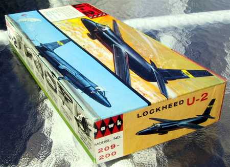
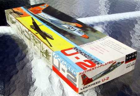
Kit History
The kit was tooled by Hawk in the 1960s and released as a U-2A, in
white styrene and also a chrome version picturing the same subject as
this feature article.
Click the
thumbnails below to view full-sized images:
Testor acquired the molds and retooled it into a U-2C with larger
intakes and a dorsal spine and the kit was also released by Italeri and
eventually made a kit of the U-2R/TR-1, of which you can read in David W
Aungst’s excellent feature here at HyperScale.
As late as 2002 Testor re-released the U-2C with new box art together
with a cart to move it around.
My interest for the U-2 started a few years ago when I bought the
Italeri TR-2 and discovered all the Cutting Edge goodies for the U-2,
and I am very impressed with the quality of the resin; it’s almost
impossible to break even the most delicate parts! At Scale Modelworld in
Telford I have bought several old U-2C kits and I plan to build many of
the variants in different paint finishes.
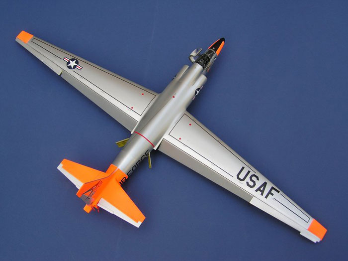
I chose the most striking scheme for my first U-2: NMF. Little was I to
know of the problems awaiting me before packing my finished model in the
box for Telford.
To convert the U-2C to an A the air intakes must be changed to the
smaller intakes for the J57 jet engine, the rear part of the intakes can
be found in the Cutting Edge set 48287 together with the flat spine and
rear fuselage, but for the front part of the intakes and the seamless
intakes with the turbine blades you must have set 48293.
Those two sets are necessary for the conversion, but when you start
cutting the styrene, why don’t you do it properly and get the other
resin sets as well!
The cockpit set 48288 is a major improvement to the kit and can not be
left out, as the set 48292 with air brakes, main wheel well and some air
scoops and finally 48298 which is the rear wheel well with the exhaust
pipe that fits snugly to the new rear fuselage.
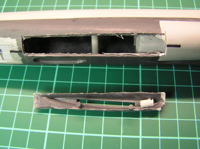
Fuselage conversion and improvement
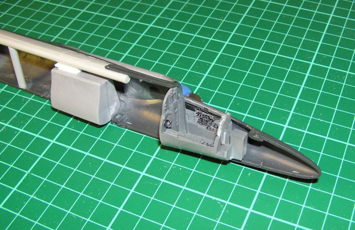
The old spine is cut away from the fuselage halves, using the resin
exchange parts to measure correctly. I strengthened the fuselage top
with a suitable straight sprue supported from the fuselage bottom.
(Picture 1)
This strengthening is necessary considering the rough handling needed
using a coarse grade file to shape the fuselage, and wet and dry sand
paper to do the finer work.
Cutting away the plastic gets most tricky where the new resin parts
meet the fin; it’s very easy to cut away too much. You must be prepared
to do a lot of work tidying up around the new parts on the fuselage. I
used CA to get a strong seam against the fuselage before starting the
abrasive work. The resin exchange parts all have recessed panel lines,
which I filled with CA glue as I wanted to make new panel lines later
all over the airplane.
Most of the parked U-2 airplanes seem to have their air brakes extended
showing the air brake interior. To replace the coarse kit items is quite
easy, starting with my Dremel tool and a sharp knife but I had to add
some thin plastic card to both the upper and lower edges of the opening
as the resin air brakes were smaller. The resin interiors are glued from
the inside.
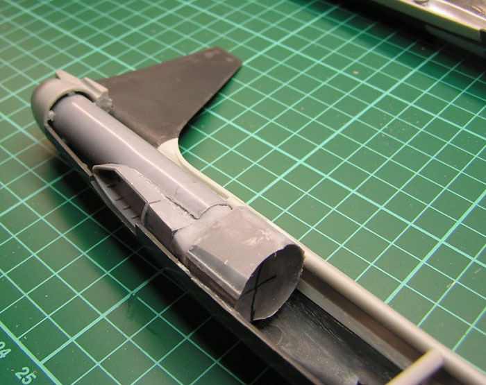
The original rear fuselage is cut off and the resin part is glued to
one of the fuselage halves, but before the glue is used I recommend
fitting the exhaust pipe. This calls for some dry fitting and cutting in
the resin lump that fits between the two air brake interiors. At the
same time the rear wheel well must fit the fuselage opening. As I said,
lots of dry fitting and maybe it’s necessary to glue some thin shims to
the rear inside of the resin tail cone to center the exhaust, but in the
end all resin was glued to the left fuselage half and the right one fit
perfectly! Well done Cutting Edge!
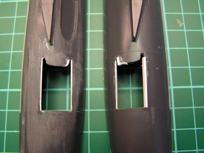
Replacing the rear part of the air intakes demands some careful cutting
close to the wing root, and the new part is glued with CA, and then the
new front part is attached. Note that the “seamless” part fits inside
the rear part with a smooth joint to the front part. I managed to
misalign the left side intake parts slightly and had to thin down the
“seamless” intake part to get an acceptable seamless fit. I used sprue
to support the inside seamless part.
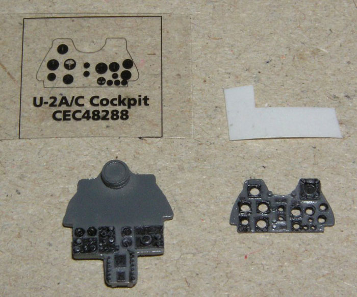
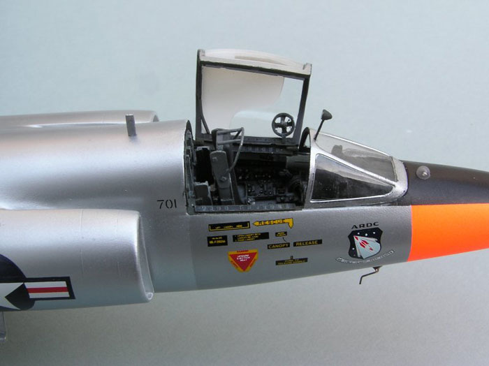
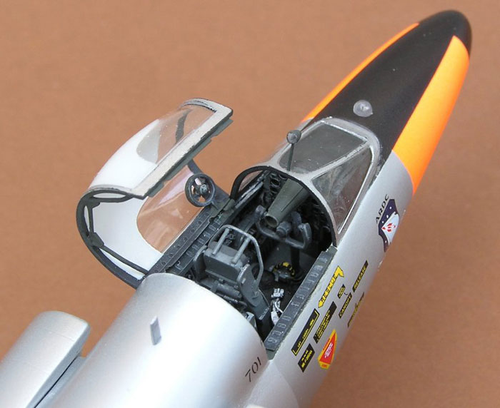
The resin cockpit comes in very few pieces; the whole tub, the seat and
the instrument panel. The entire cockpit interior was painted a medium
to dark gray, and the instruments were hand painted black. A white
plastic card was used behind the printed clear acetate instruments
dials. (Picture 5)
The resin instrument panel has an interesting feature; the instrument
dials are not bare holes through the panel but have very thin dials that
may give a good result when you don’t use the clear acetate dials, but I
chose to sand this gimmick off.
The clear acetate sheet was glued to the white backing with epoxy glue,
and all was glued to the instrument panel, but before assembling the
panel all visible parts except the dials were airbrushed satin.
All internal tabs where the cockpit tub should be located were cut off,
and the tub was dry fitted. As expected a perfect match and even the
side panels I glued to the fuselage halves fit perfectly.
The main wheel well was also installed in the left fuselage half, and to
the top strengthening sprue with a shim.
The cockpit set contains an ejection seat, whereas most U-2A planes had
ordinary seats installed. Eventually most had their seats replaced with
ejection seats, a good measure especially after several pilots were
lost, when they were unable to leave their cockpit or hit by the tail
plane.
The seat was painted the same gray as the cockpit, with a black seat
cushion and the integrated seat belts were painted gray silver. There
was a resin part for the tube on top of the seat that breaks the canopy,
but I made a new from thin piano wire.
Click the
thumbnails below to view full-sized images:
Final fuselage assembly
More testing of the fit between the fuselage halves before applying
CA glue to all resin surfaces meeting plastic, and finally I joined the
fuselage halves over all this expensive resin! It’s massive!
When the CA glue had set the plastic seams were filled with liquid
glue and the fuselage was held together with both tape and different
clamps.
One part I did not glue: the fin. I discovered it was not orientated
exactly as I expected so I chose not to glue it yet.
After a week the fuselage was retrieved to the work bench and I studied
it carefully. I had a notion something was wrong when I was dry fitting
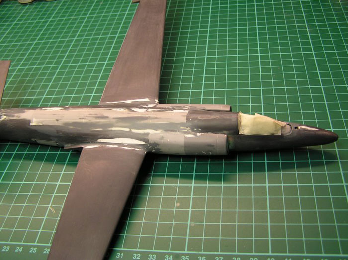
the fuselage, and now I could perform the real tests.
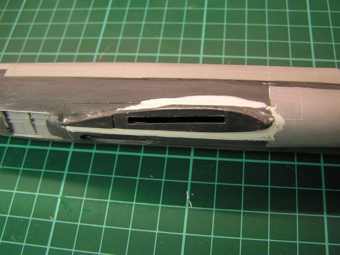
From straight ahead it seemed the air intakes and the wing roots were
not really in unison. And when I compared them to the cockpit my
suspicion was confirmed.
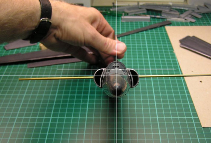
The lower line in the picture is the cockpit sill and the upper line is
the top of the air intakes, and through the slots for the wing tabs I
inserted a tube. The molded wing roots doesn’t seem to be in the same
height, they differ 1,5 - 2 mm. I don’t know if this is an inherent flaw
in the kit, or if my excessive conversion had distorted the fuselage,
but examining my other U-2C kits I found signs of the problem comparing
the panel lines around the wing roots of the left and right fuselage
halves.
It was impossible for me to ignore this problem, because if I would have
assembled the wings they would either have been on different levels or
not parallel to the inlets and the cockpit.
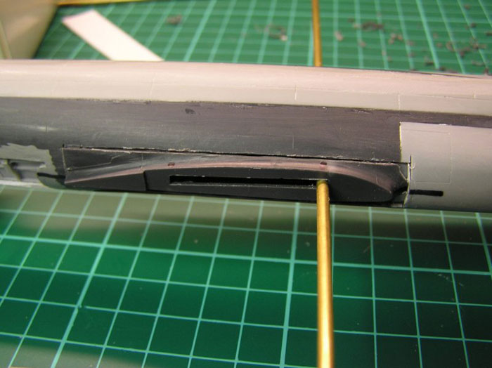
I decided to tackle the problem right away, at 9 pm on a Saturday
night. I thought it would be easier to move the right wing root up than
it would be to move the left wing root down, and a square was marked
where I would cut around the wing root. The lateral cuts were made with
a razor saw and the horizontal with my Dremel.
The rough edges in the hole and on the wing root piece were cleaned, and
when inserted against the top edge in the hole the wing root was 1,5 mm
higher than before, and more or less in level with the left one. A
plastic card shim of 2 mm was glued below the relocated piece and CA
glue was used abundantly around the seams. All this took less than 30
minutes, much less than my anxiety period before I dared trying.
But all was not perfect yet. Theoretically this was an easy operation,
but in reality there was a problem as the wing root is located on the
rounded surface tangential to the arc of the fuselage, and when I moved
it upwards the upper part was outside this arc and the lower part was
inside. A lot of Milliput and sanding was necessary but it turned out
good and I was very satisfied with my modification which is virtually
impossible to trace when the model is ready.
Click the
thumbnails below to view full-sized images:
Once again the fuselage was put aside to completely cure for a week.
After that I started with a coarse file and gave it a straight dorsal
profile cutting away CA glue, plastic and resin, then sanding and
finally I applied Milliput where it was needed. The process was
repeated, with painting in between with a contrasting color, for a week
before the result was acceptable.
Click the
thumbnails below to view full-sized images:
 Home
| What's New |
Features |
Gallery |
Reviews |
Reference |
Forum |
Search
Home
| What's New |
Features |
Gallery |
Reviews |
Reference |
Forum |
Search