|
This is part
three of my marathon three part posting on my
U-2S "Senior Span/Spur" project.
After over three
and a half years on my work bench, I can finally
call this one DONE.
In parts one and
two of my U-2 project build posting, I discussed
a brief history of the U-2 and the building of
my U-2S model. In this part I will discuss the
painting and finishing of the model.
Follow these
links to get to the other parts of this posting.
| |
Part One: |
Aircraft History, Model
Kit Description, and
Fuselage Interior Construction |
|
| |
Part Two: |
Fuselage Exterior,
Wings, and
Completed Airframe Construction |
Model Surface
Details and Scribing
|
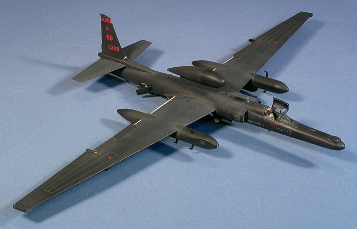
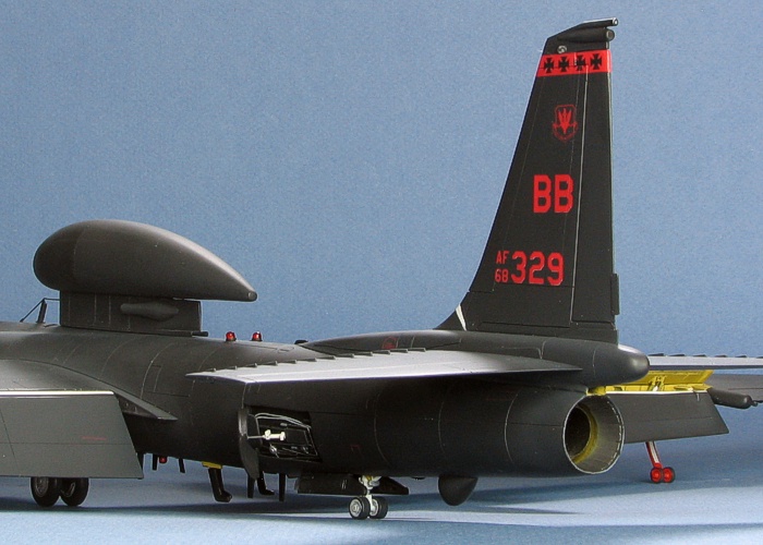
There is really only one painting option for
making a late model U-2S -- black, black, and
more black. With this one camouflage option
available, the question became, "How do I make
an all-black aircraft interesting?". I decided
that I needed airframe details to help fill in
the long areas of flat nothing. To that end, I
postponed painting for just a little while
longer and scoured over all the U-2 references I
had looking for panel lines and access panels on
the airframe. I figured that some extra scribing
would go a long way to adding interest into the
surface of the model.
Even before I started painting, I was
starting to really like the way the model was
looking with all the added access panels and
details.
Some further scrutiny of the Senior Spear
antenna farm on the belly of the aircraft and
the provided blade antennae from both Cutting
Edge's update set and Italeri's
Senior Span kit made me decide to handle the
blade antennae a little differently than I had
originally thought. I already had drilled holes
in the locations I thought I wanted the blade
antennae to be, but a late discovery of a
bottom-side image of a U-2S in the landing
pattern changed my opinions of the locations I
chose to drill the holes. So, I filled the holes
and relocated the antennae as outlined below.
| |
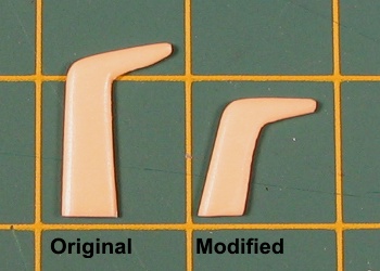
Corrected Blade Antennae
|
Also, I knew that both the Cutting Edge
and Italeri blade antennae were too big.
I had not taken time to determine just how much
they were too big. After some careful
measurements from the pictures I had, I did the
math to find that both the Cutting Edge
and Italeri blade antennae were
substantially too big. Both were incorrect in
the angle that the "hockey stick" antennae were
mounted. I liked the shape of the Cutting
Edge blades better, so I started with theirs
and trimmed them down to more appropriate sizes.
See the image to the right for a comparison of
the original and modified antennae.
The first thing
you will note in the picture is the height of
the blade antennae. I cut off about 0.1" inches
(measured at the leading edge) from the base of
the antennae. I also changed the angle of the
base so that the "blade" of the "hockey stick"
would be more parallel to the airstream. The
shortening of the blade in addition to the
change in angles substantially reduced the
overall height of the blades, solving the
problem of having them hit the ground on the
complete model. Additionally, I slightly reduced
the width of the blade and the length of the
tip.
Using my newly modified "hockey sticks" as a
basis, I then cut down the other blade antennae
to correspond to the size change in the "hockey
sticks".
Since I was cutting the blades from their
mounting plates in order to fix their size, I
decided to make my own mounting places (thinner)
out of 0.010" strip styrene and attach the
mounting plates to the aircraft before painting.
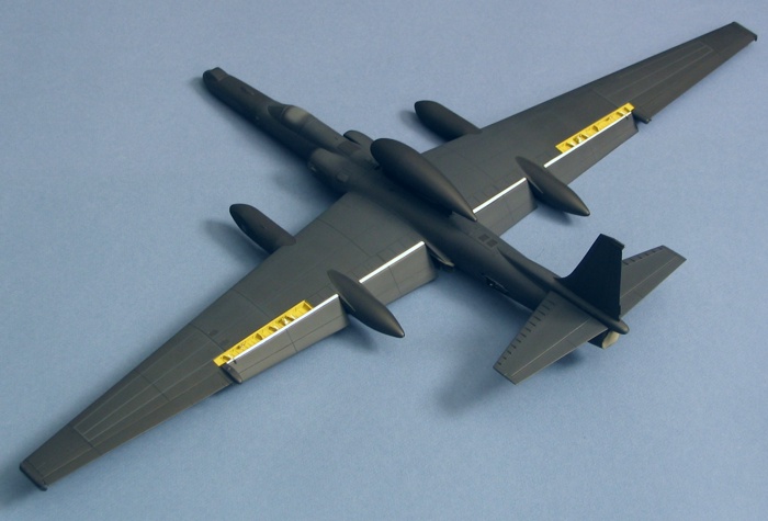
The images below show one of the reference
images along with a picture of my model (before
painting). The model image shows the final
positions of the blade antennae (really just the
mounting plates) as best as I could interpret
from the reference images. Note these are only
marginally different from the positions given in
the Cutting Edge instructions.
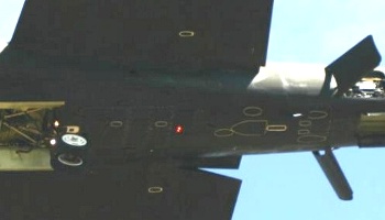
Antennae Positions --
Reference Image |
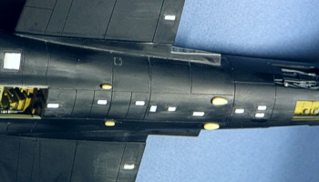
Antennae Positions --
Model |
After adding all the three-dimensional
details that I could find, it was now time to
start painting. I wanted to verify all my work
was clean, so I did something very out of
character for me and primed the model. I used
Model Master D.Ghost Gray and painted the
whole model. Had I known the trouble this would
cause me later, I would have decided not to
prime the model.
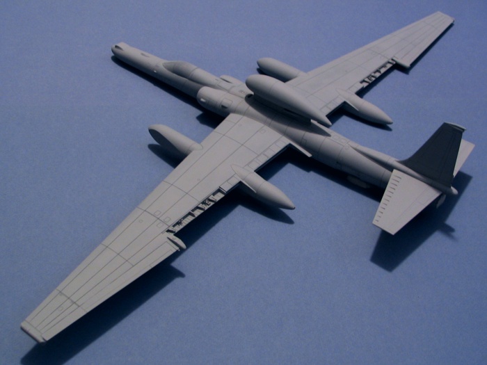
Primed Model |
After having a
mostly black plastic model (with some gray resin
portions) on my desk for the last couple years,
it seemed strange to see this all gray model.
One thing was very evident -- the primer showed
that my scribe lines were way deeper and more
pronounced than I would have liked, but it was
well past the time to fix that, so I moved on.
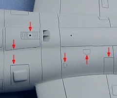
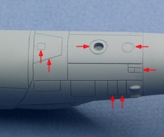
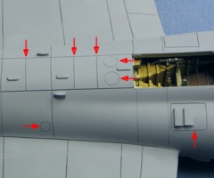
The following images show some of the additional
scribing I added to the model. The red arrows in
the images highlight the additional lines.
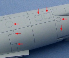
Upper Rear Fuselage |
Rear Fuselage Sides |
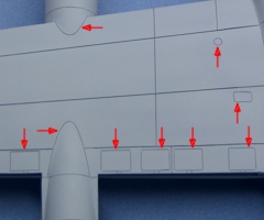
Upper Mid-Fuselage |
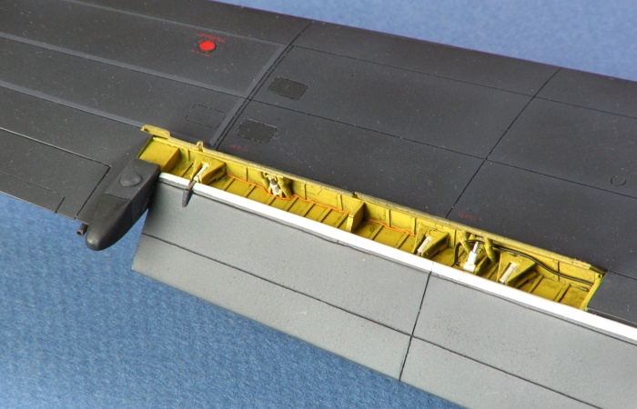
Lower Forward Fuselage |
Flap Actuator Access
Panels |
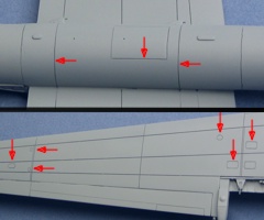
Fuel Cell and Wing Tip
Access |
Pictures from
the World Airpower Journal issue that covers the
later U-2 had plenty of shots of U-2 aircraft
showing a wide variety of weathering patterns. I
decided to try to capture a weathered look
without making the aircraft look too busy.
The first thing I had to do is start thinking
in terms of very dark gray, not black. This
would then give me the latitude to vary the
shades and simulate a paint scheme similar to
what I was seeing in pictures. I started by
painting the whole model in Model Master
Interior Black. Previous usage of this color by
me over bare plastic showed it to be a nice
extra dark gray color. Over the gray primer
paint, however, the color turned to a near black
color. This was much darker than what I was
initially intending as the overall color of the
model.
Now I had to decide what to do. The problem
was that I liked the dark color I got when
applying this paint over the gray primer. I
decided to keep it, which changed some of my
other plans for painting on the model. I masked
off and painted the ASARS II nose in a very thin
true black. Most all pictures of ASARS equipped
aircraft from the 1990s show the nose being
darker than the rest of the aircraft. I kept the
paint thin and just misted it on until I had
slightly darkened the nose. I did the same
darkening to the noses of the super pods, the
forward portion of the Senior Span pod, and the
engine intake lips.
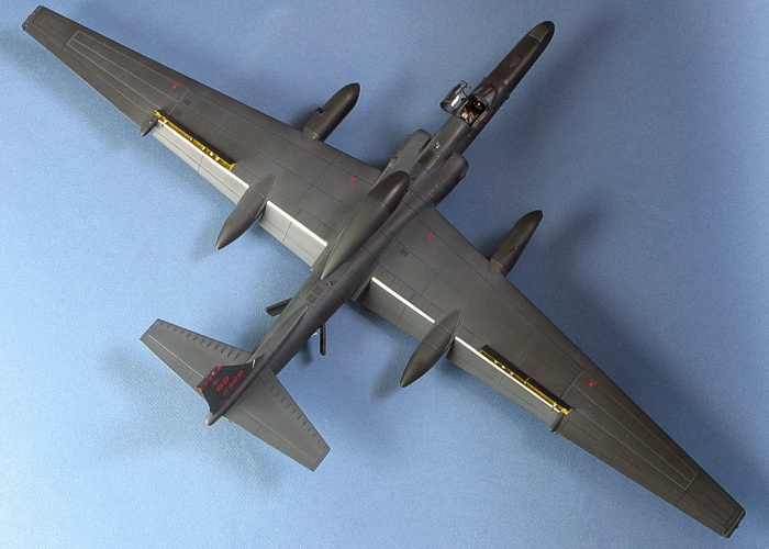
Most aircraft in pictures show a faded
pattern across the upper wings and fuselage with
very slight darkening near panel lines. I mixed
up some Engine Gray (F.S.36076) and misted it in
a wide spray pattern across the inboard wings
and the upper fuselage. Before doing this paint
fading, I masked off the fairings for the super
pods. Images showed these were generally darker
than the surrounding wing areas, probably
because they are removable and thus not as
weathered.
A couple images showed aircraft where the
outer wing fuel cells had been recently
maintained. This resulted in a dark gray outline
to the panels. I masked the wings and applied
this outline using Engine Gray (F.S.36076).
While painting full-strength Engine Gray, I also
masked and painted the panels under the nose, in
front of the ECM blisters on the engine intakes,
and the front and rear faces of the ECM pods on
the wing tips. Most images show these areas
being a lighter color than the rest of the
airframe.
The "scuff zones" on the upper wing flaps and
the small pie slice at the front of the vertical
tail are white. I had painted these in gloss
white and masked them before starting the
overall colors. The spoiler wells are Chromate
Yellow with the actuator pistons painted white.
I have no detail color references for the wells,
so I chose to make the pistons white just to
liven up the area.
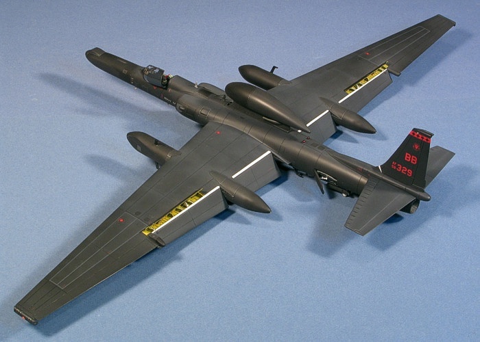
Ready for Gloss
Coating |
With all the
major area painting done, I was really starting
to like the looks of the model. Next, I held my
breath and applied a gloss coat using Floquil
Crystal Coat to the whole model. This gloss coat
changed the colors of the model considerably.
All the things that should have been darker but
did not seem to be much darker suddenly were
darker. I felt vindicated over the color choices
I had made and that the color variations were
not too over-done (a BIG fear I had before the
gloss coat). Then, it was time to start applying
decals.
The decals for the unit markings came from
the Cutting Edge TR-1A / U-2R/S "Dragon
Lady" sheet CED48026 (seen below). While there
are several nice tail art aircraft on this
sheet, they all go on aircraft from the 1991
Desert Storm conflict. I was limited on using
any of these because of the airframe details I
already had applied to the model. Specifically,
the GPS dome fairing on the left wing was not
present for the 1991 Desert Storm period.
Besides, what I really wanted to build was an
aircraft that used the "BB" tail code like the
one I saw at the Andrews AFB air show. So, I
ignored the neat tail arts and just used the
generic "BB" tail codes and numbers from the
bottom portion of the sheet.
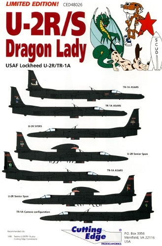
Decal Cover Page |
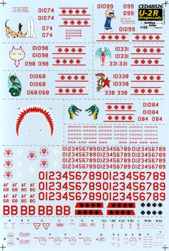
Decal Sheet |
The Cutting
Edge sheet I originally purchased years ago
turned out to have a severe registry problem.
All the "BB" and serial number decals had the
white backing showing from the sides of the
markings, making them look like they were
shadowed. A quick trip (well, not SO
quick being a six hour round trip) to Meteor
allowed me to pick up a replacement. My
off-register sheet must have been a fluke, as
the first two sheets I picked off the pile were
in perfect register. The sheet includes a bit of
airframe data markings. Loving data markings, I
could not help but to add these to the model,
too. Most U-2 aircraft seem to maintain their
data markings pretty well, so these are not out
of place.
Studying the pictures of the aircraft I saw
at the Andrews AFB air show, I saw many airframe
panels had silver/gray fasteners lining the
panels. I decided it would make this all black
aircraft look more interesting to incorporate
these fastener patterns into the model. I got
the idea for this from Gekko Graphics
silver scratches weathering decals. I measured
the panels that were to get the fastener decals
and drew up the art work on my PC. After
cross-checking and verifying the patterns and
sizes, I printed them on my ALPS printer using a
silver foil ribbon. Covered with gloss and flat
coatings, these dulled down nicely to a metallic
gray color.
The following is the art work I used for my
custom decals (reduced in size to save space). I
also changed the background color in this image
to make the fastener patterns easier to see.
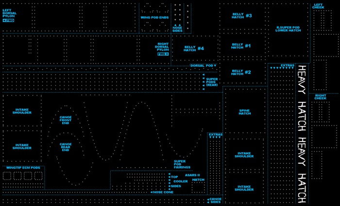
Custom Decal Art Work |
When the decals
had dried, I applied another gloss coat to seal
them. Then, I applied a satin finish to the
entire model using Floquil Flat Finish. I
have never gotten a flat finish from Floquil
Flat Finish, instead always giving me a nice
satin finish. Lastly, I applied a flat coat to
specific parts of the model using Polly Scale
Flat Finish. After this flat coat, the red of
the tail markings seemed extremely bright on the
dark airframe. I toned down the red color by
doing a light misting of black over the tail.
The effect better captured the look of the
markings I saw on real aircraft in pictures.
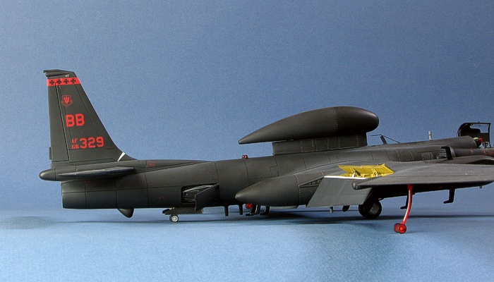
Decaled and Satin/Flat
Coated |
For weathering,
I did very little beyond what I had already done
with the colors of the paints I used. Most of
the weathering was built into the already
applied color coatings. Also, the scribed lines
were deep enough to be seen without needing any
washes applied to them. I did do some minor dry
brushing to pop out and enhance a few surface
surface details (like the stiffening ribs on the
tails).
For the record, this black finish on the
model was more troublesome than other color
finishes I have applied. The biggest issue was
that I could not make touch-ups without having
them show. It was almost as bad as a natual
metal finish in this respect. What I fould is
that the colors painted from the bottles
(brushed or air brushed) were very different
from the same bottled colors that had been
gloss, satin, and/or flat finished. I have some
areas on the bottom that really got me annoyed
around the blade antennae because my touch-ups
are not matching the surounding paint. Oh
well...
With the model painted and decaled, it was
time to work on the landing gear. With all the
detail I had added to the rest of the model, I
did not want to come up short on the landing
gear, so I started doing some scratch building
and detailing. The following image shows the
landing gear items that I updated.
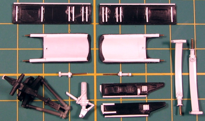
Updated Landing Gear
Items (Mostly Unpainted) |
What I did to
the landing gear items is as follows:
- Main Wheel Well Doors: The kit
pieces are not bad. They only lacked some
inside ribbing. I added the ribbing with
0.010"x0.020" styrene strips. I also added
0.020" square strips on the mounting edges
of the doors to provide a lip to assist in
aligning the parts when I attached them to
the model.
- Main Landing Gear: Pictured is
the Cutting Edge landing gear strut
that I made the master for with the
kit-provided landing lights attached to it.
On looking closer at the strut, I found I
needed to add some small wiring harness
details. Not easily visible in the images,
after completing the painting of the strut,
I added some black hydraulic lines and
wiring to the back side of the strut and two
MV Lenses for the landing lights.
- Tail Wheel Well Doors: Out of the
box, these could work, but I have images
that showed details that the kit had missed.
I cut holes in the doors and added vent
louvers in the rear sections. I added a
scoop to the leading edge. I also added the
retraction linkage connect point on the
inside. Like on the main wheel well doors, I
also added 0.020" square strips on the
mounting edges of the doors to provide a lip
to assist in aligning the parts when I
attached them to the model.
- Tail Landing Gear: The kit piece
for the strut is quite close to the real
thing. All I did was add the linkage lines
for the steering collar and drill holes to
receive the linkage arms for the wheel well
doors.
- Wing Pogo Struts: The pictured
items are already painted white. I cut down
and re-built the mounting shanks, replacing
the kit's plastic mounting pins with brass
wire. This would help the pogos survive
years of display on my model shelves. I also
added the tie-down lugs to the front and
back of each pogo.
- Speed Brakes: Like the main wheel
well doors, the speed brakes are not bad
right out of the box, but I was not happy
with the thinness in the kit pieces. There
were also a series of knock-out pin flaws on
the inside surfaces. I decided to re-build
the inner side of the speed brakes. This
made the brakes more bulky as well as
covered the knock-out pin flaws.
- Speed Brake Actuators: The kit
piece for these were too small. Besides,
having rebuilt and deepened the speed brake
wells, I needed longer actuators than what
the kit provided. The only course was to
scratch build new actuators from styrene rod
and brass wire.
After all the updates were done, I painted
the pieces and attached them to the model. The
one landing gear item I did not change from the
kit was the rather complicated looking
retraction linkage for the main wheel well
doors. Testors/Italeri seemed to do quite
well on this piece, so I just removed the mold
marks, paint it, and installed it as is.
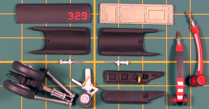
Updated Landing Gear
Items (Painted) |
Now that the
model was sitting on its landing gear, I could
start adding all the blade antennae. Having
already attached the mounting plates of the
antennae and pre-drilled all the antennae
locations before painting, the antennae were
fairly easy to attach. I drilled a hole in the
bottom of each antenna with a #80 drill bit and
glued in a piece of fine brass wire. The wire
acted as a locator pin and made a positive
attachment to the aircraft in each place I had
drilled a hole on the bottom of the model.
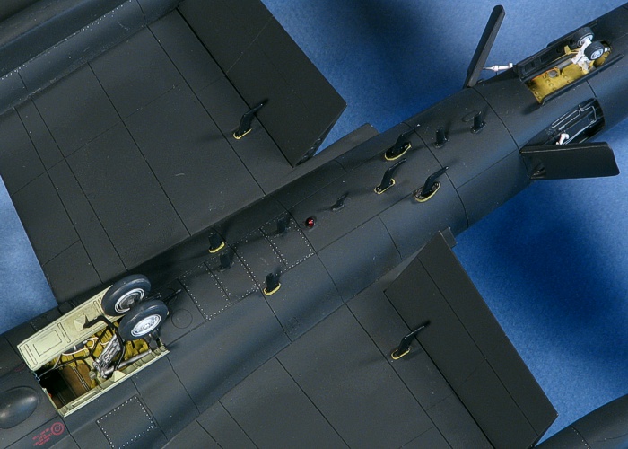
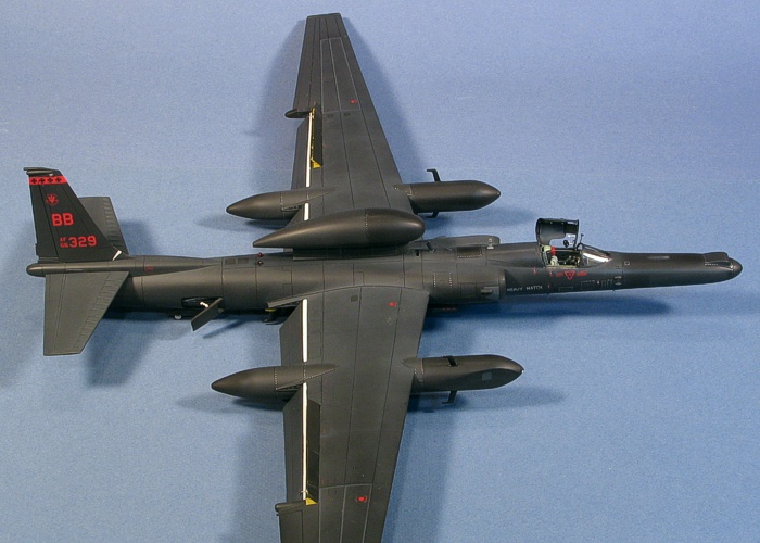
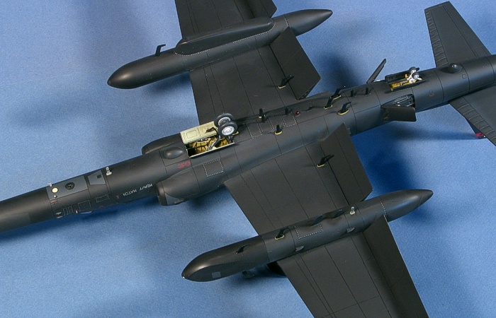
Underside Antenna Farm
While attaching the blade antennae, I painted
some of the antennae bases in the light
yellow/green that I used in the wheel wells.
Then, a quick swipe with a paint brush colored
the actual blade antennae. The Cutting Edge
instructions state that the antennae vary in
color. I found most pictures showed black
antennae, so I chose to make most of them black.
For variety, I did pick off a couple odd
antennae in medium gray. Pictures also showed
the antennae were glossy finished. After the
colored paint dried, I gave each blade a swipe
of clear gloss paint.
Attaching the wing flaps and spoilers came
next. No matter how long I had played with the
detail fit of the flaps, I always found I could
tweak something else to improve the fit even
more. Finally, I gave up and added glue.
The spoiler wells were detailed with some
fine wire. I have no pictures of this area on
the real aircraft, so I just added the wire to
make things look busy. The wire is
ignition wire for 1/24th
and 1/12th
scale car models.
Left Wing Spoiler Well
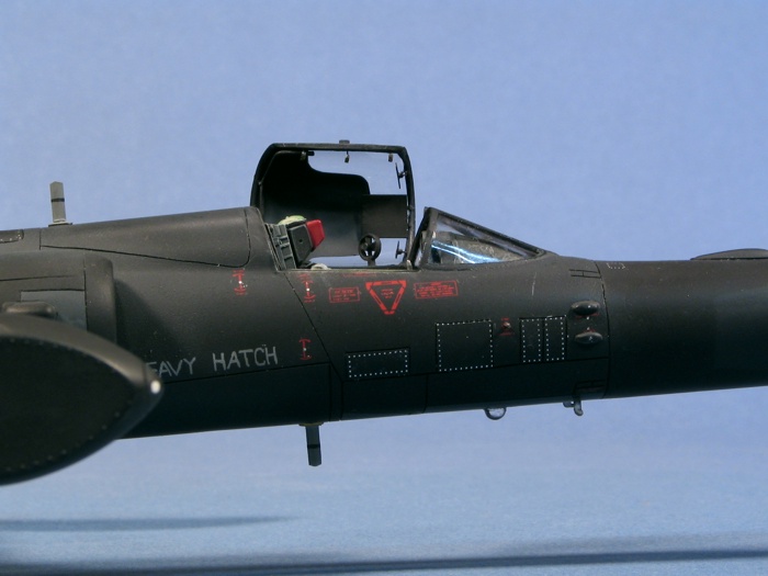
As is almost always the case for me,
detailing around the cockpit and the interior of
the canopy were the last things I did on the
model. I scratch-built the defogging pipe in the
rear section from copper wire. I added the
latching handles on the right frame edge with
fine brass wire. Finally, I added the rearview
mirrors and movable sunshade with its guiderail
to the front edge using fine brass wire and
sheet styrene. Cutting Edge provides a
nicer version of the personal fan for the left
side of the canopy than the kit-provided
version, so I used the Cutting Edge
version. Italeri's instructions tell you
to mount the fan to the canopy glass, but it
really is attached to the canopy frame. I
removed the molded locator lines from the glass
and attached the fan to the canopy framing.
Research showed that the majority of the
canopy is clear plexiglass with only a couple
inches of frame running around the outer edge.
What looks like a solid upper portion is really
a self-adhesive sunshade applied from the inside
of the canopy glass on the upper rear section.
The kit molds this detail correctly with the
line for the shade only present on the inside of
the canopy. I masked the inner canopy and
painted the sunshade from the inside.
One item to add on the upper left windscreen
frame was the rearview mirror. The kit-provided
piece for this was way too bulky, so I
scratch-built a new mirror from a piece of
styrene rod, some 0.005" brass wire and some
0.005" sheet styrene. This looked much better
and was more dainty, like the one on the real
aircraft.
With all this work done around the cockpit
and canopy, I attached the canopy in the open
position and completed the project.
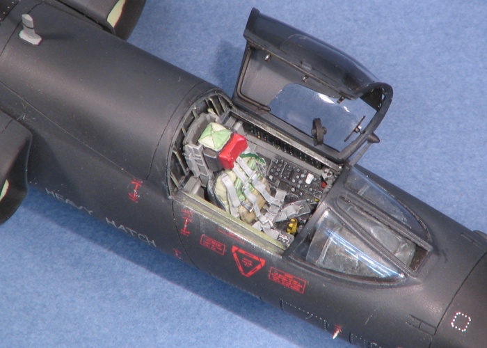
Cockpit and Canopy
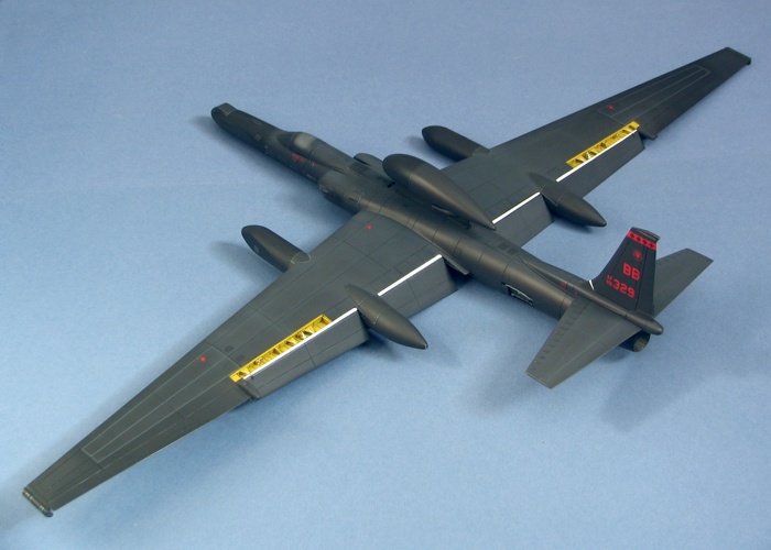
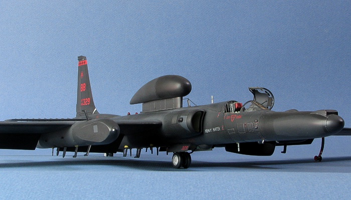
So what
EXACTLY have I built?
|
This picture was the prime inspiration for
the project.
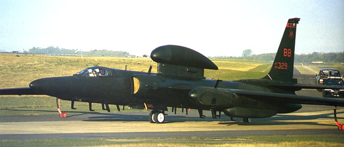
68-10329 Reference Image
This biggest difference between the above image
and my model is the ASARS II nose. While I have
other images showing that 68-10329 can carry the
ASARS II nose, the above image shows it at a
time when the ASARS II nose was not being
carried. This aircraft (and more specifically my
model) bristles with antennae all over its
surfaces. What are they all and what do they do?
From studying various books, I have learned the
following.
- The nose is the ASARS II
synthetic aperture radar. This side-looking
radar is used to make detailed radar maps of
target areas from considerable stand-off
distances. Sample images in books show
astounding clarity in the images, and I am
sure that the images declassified for
publication are only a fraction of the true
capability of the system.
- The antenna farms on the lower airframe
and the canoe fairing on the left super pod
are all part of the Senior Spear
COMINT system which gathers and classifies
various forms of communication signals. The
flattened portions of the forward sections
on the super pods are for Senior Ruby.
This is an ELINT system that gathers
information on radar emissions. The
combination of Senior Spear with Senior Ruby
together on one aircraft is also referred to
as Senior Glass.
- The four "hockey stick" blade antennae
mounted on the top and bottom of each of the
Senior Ruby super pod noses are unknown to
me. The image above of aircraft 68-10329 is
the only image I have showing these, and
since I wanted as many antennae on the model
as I could, I added them. Perhaps they were
an experimental extension of the Senior
Spear fit.
- The dorsal antenna pod is a satellite
up-link antenna to allow real-time
interpretation of the information gathered
by the U-2. It is referred to as either
Senior Span or Senior Spur.
Senior Span is for transmission of SIGINT
data recorded through the Senior Glass
systems. Because I also attached the ASARS
II nose on the model, this aircraft could
have a Senior Spur installation which
transmits radar imagery recorded by the
ASARS II system. Differences in the
transmission process dictate that the dorsal
pod is either Senior Span or Senior Spur. It
can not be both. The external details of the
pod appear to remain the same, no matter
whether Senior Span or Senior Spur are
inside.
These are my best guesses based on what I
have read. Considering the classified nature of
the U-2, these interpretations could be correct
or just elaborate fabrications. I do know that
some of the references I checked contradict each
other on various points. Whatever the case, all
the assorted antennae, bumps, and bulges give
the model a very determined look that lives up
to the U-2 pilot's motto -- In God we
trust, all others we monitor.
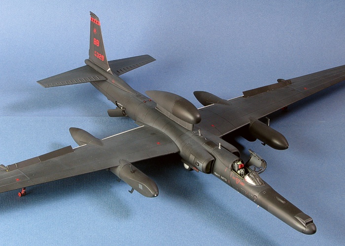
Did I mention that the finished model is
HUGE?!?! The completed model has a 26 inch
wingspan. I need to find a creative way to fit
this model onto my display shelves in the living
room. The following image shows just how big the
final model is as I proudly hold it up for the
camera.
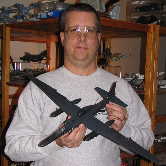
Dave Aungst Holding the
Completed Model
I believe all the update sets I used on this
model are still available from Cutting Edge.
If you get the current Italeri "Senior
Span" release, you really will not need the
Cutting Edge Senior Span/Spur/Spear set. The
ASARS II nose fit problems are not impossible to
overcome, but they will require time to work
out.
This model is a record-breaker for me.
- It holds the record for the highest
number of hours I have invested into any
single model -- 180.8 hours. And,
this time tally does not include a
further 86.2 hours I spent building
the masters for some of the U-2 update sets
I incorporated into the model. Just the
"extra detailing" time alone -- 82.3
hours -- is double the time a "normal"
project build would take me.
- The work I did constructing the master
for the main wheel bay constitutes the
largest pure scratch-building effort I have
yet to undertake. Scratch-building the tail
wheel well / engine exhaust and wing flaps /
spoilers just added to the tally.
- It has the largest amount of resin
updates that I have ever put into any one
model. I used a total of seven different
resin update sets on the model that replaced
over half the kit parts and about 25% of the
overall volume the original model with
updated, enhanced, or otherwise changed
pieces. Interestingly, there are no etched
metal pieces anywhere on the model.
I really enjoyed building this model,
although I am really, REALLY, REALLY
tired of black finishes for a little while. And,
in the process of researching for the project, I
learned that there is much more to the U-2 than
what meets the eye.
(Newest to Oldest)
-
U-2R/S
Walk Around by David W Aungst
On-Line HyperScale Reference, 2003
-
U-2: The
Second Generation by Chris Pocock
World Airpower Journal, Volume 28, AirTime
Publishing, 1997
-
Dragon
Lady by Ted Carlson / Toyokazu Matsuzaki
Koku-Fan Magazine, Volume 1996-04, Bunrin-Do
Company, Limited, 1996
-
Recce Tech
by Paul F Crickmore
Osprey Color Series, Osprey Aerospace
Publishing, 1989
-
U-2
Spyplane in Action by Larry Davis
Squadron In Action #86, Squadron Publishing,
1988/2002
-
Lockheed
U-2R/TR-1 by Jay Miller
AeroFax MiniGraph #28, AeroFax, Inc.,
1988
-
Lockheed
U-2 by Jay Miller
AeroFax AeroGraph #3, AeroFax, Inc., 1983
|
 Home
| What's New |
Features |
Gallery |
Reviews |
Reference |
Forum |
Search
Home
| What's New |
Features |
Gallery |
Reviews |
Reference |
Forum |
Search