|
Focke-Wulf Fw 190D-9
Superdetailing the Big Tail
Dora
by
Doowan Lee
|
|
|
Focke-Wulf Fw 190D-9 |
Part One
building the wings, fuselage
and engine

Tamiya's
1/48 scale Focke-Wulf Fw 190D-9 is available online from
Squadron
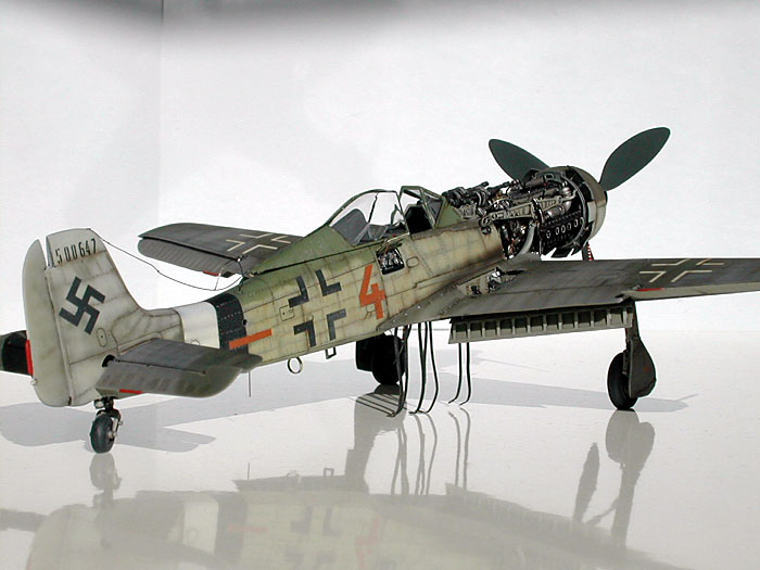
This is Tamiya's 1/48
scale Focke-Wulf Fw 190D-9 detailed with several update sets and many scratch-built
parts.
Click the thumbnails below to view larger
images:
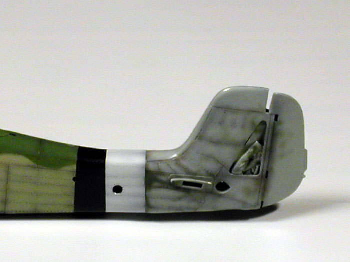
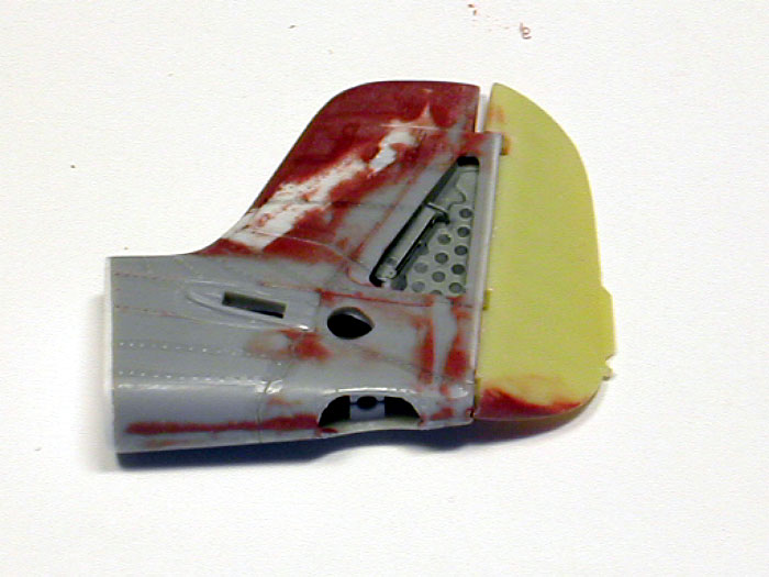
Wings and Tail
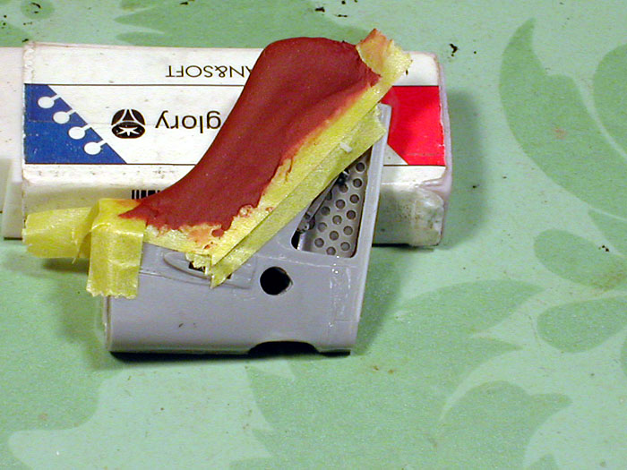
Since the Fw 190D-9 is a very popular WW II airplane, I was looking for
something that had not been done.
Having reviewed as many internet model
articles on the airplane as possible, I realized that few Fw 190D-9s had
both a superdetailed Ta-152 tail and wheel well. The wheel well could be
precisely correctly with the MDC update set. However, superdetailing the
big tail was a bit more complicated task than I expected since I couldn’t
just use aftermarket resin tails. An easier solution would’ve been
kit-bashing an Italeri Ta-152H kit. However, I didn’t feel like wasting
money and a perfectly fine kit. As a result, I ended up using a regular
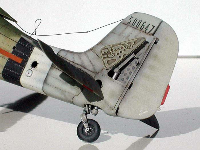
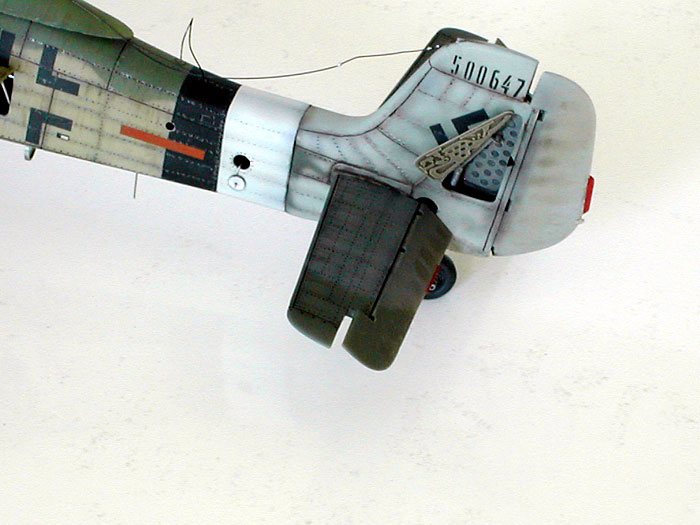
tail and heavily modify it with putty and my trusty dremel tool. The tail
wheel service panel was easy to simulate since I had all the necessary
parts from the FM detail Fw 190D-9 update set.
Modifying the outside was a completely different
story. In retrospect, I would’ve saved a lot of time and trouble by simply
kit-bashing the Italeri Ta-152H.
Click the thumbnails below to view larger
images:
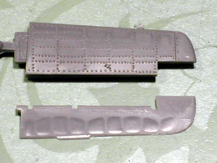
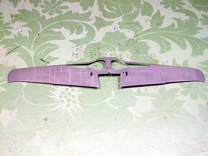
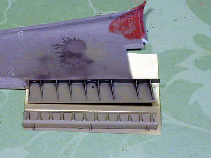
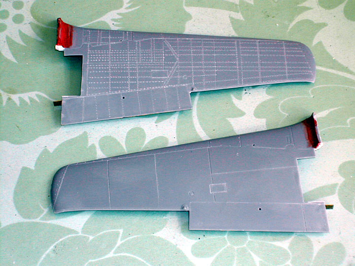
For the wings, I had to correct several panel lines which were omitted in
Tamiya’s 190D-9. I used Parts and Accessories’ flaps and Cutting Edge’s
control surfaces. Fitting the flaps was pretty tricky and required many
hours with my dremel tool. The flaps themselves required a lot of careful
bending and assembly, but the details were excellent.
Click the thumbnails below to view larger
images:
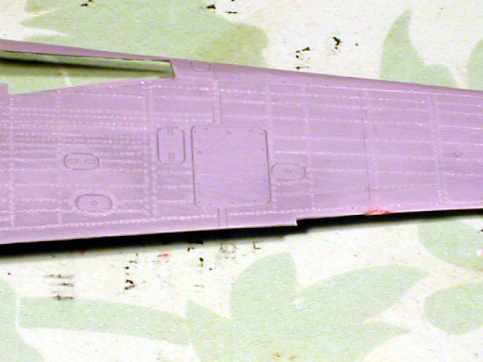
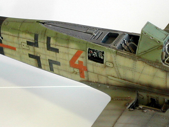
Next was simulating rivet
marks.
I have studied all my
reference photos on the aircraft and realized that the surface was not
very smooth at all.
Although I tried to justify not doing this tedious time-consuming
detailing, all the reference photos of the 190D-9 showed fairly visible
rivet marks even from a distance. In fact, in almost all close photos, I
could see distinct and worn-out rivet marks throughout the aircraft. Rivet
marks were especially visible around the cockpit and accessible panels and
hatches.
This observation led me to simulate rivet marks on the entire model.
Relying heavily on “Aero Detail: Fw 190D,” I used a sharp scribing pin to
individually simulate the rivets. Although it was very time consuming to
say the least, I think this is the best way to do the job. I tried
different types of metal gear wheels and other tools, but they did not
give me the exact round shape or density of the rivet marks. I used
masking tape to guide each panel lines.
It took a few days plus a couple of blisters on my thumb. Well, there was
no deadline, thus I went on with the task. I paid extra attention to keep
the rivet marks subtle. This is done by sanding the entire aircraft with
2000 grit sandpaper until the rivet marks were subtle enough to be seen in
close proximity but fade away from a distance. In retrospect, I am happy
with what I did to simulate rivets all over the plane. However, I don’t
think this will be something I would do on a regular basis for my future
projects.
Click the thumbnails below to view larger
images:
Fuselage and Engine
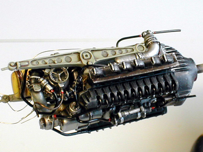
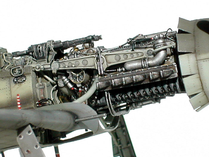
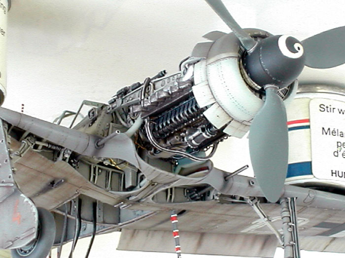
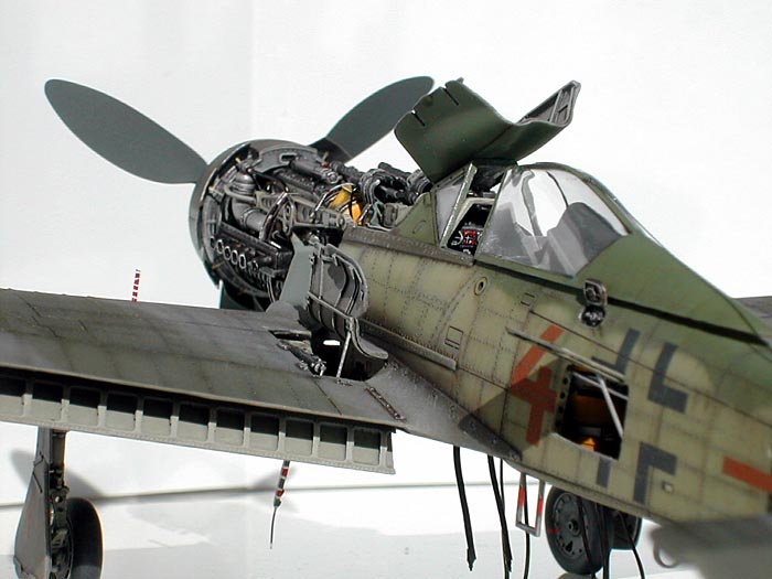
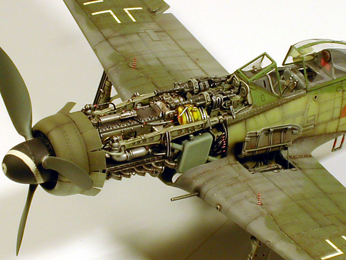
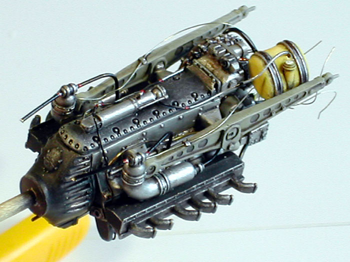
As for the engine,
I compared several aftermarket sets. Aires’ engine looked great and
dynamic but a little oversized. Verlinden’s engine was nice, but
undersized and a bit simplified. After measuring and comparing with all
the reference books I have, I concluded FM Detail’s interpretation of the
Juno engine was the most accurate. The support rails attached to the
engine were scratch-built as well. I relied on Brett Green’s Fw 190D-9
close-up article at
http://www.clubhyper.com/reference/fw190d9enginereferencebg_1.htm for
wiring and extra detailing.
Click the thumbnails below to view larger
images:
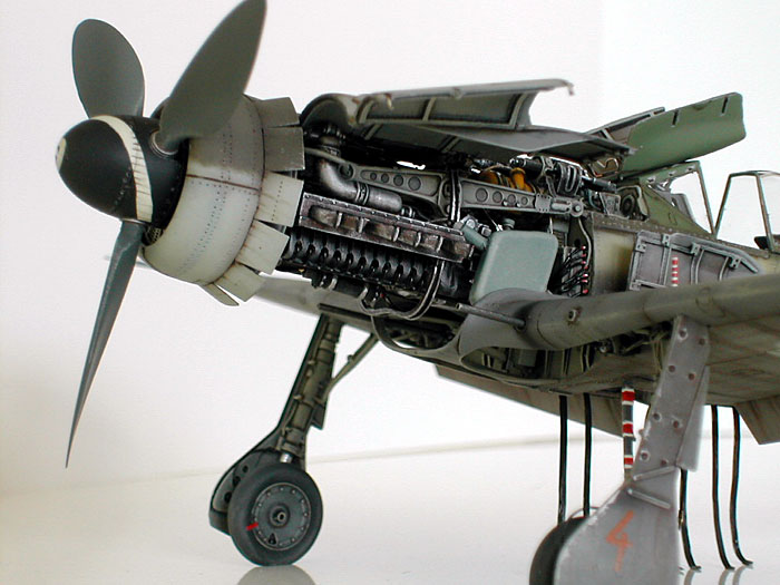
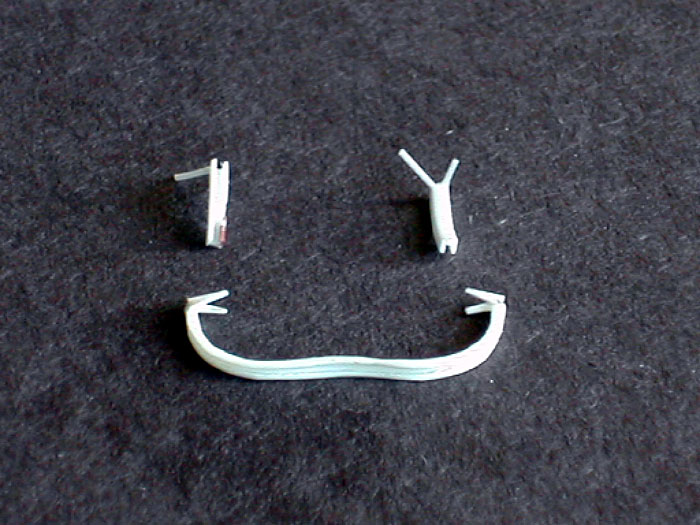
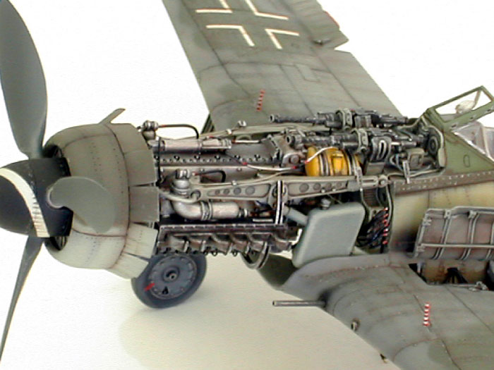
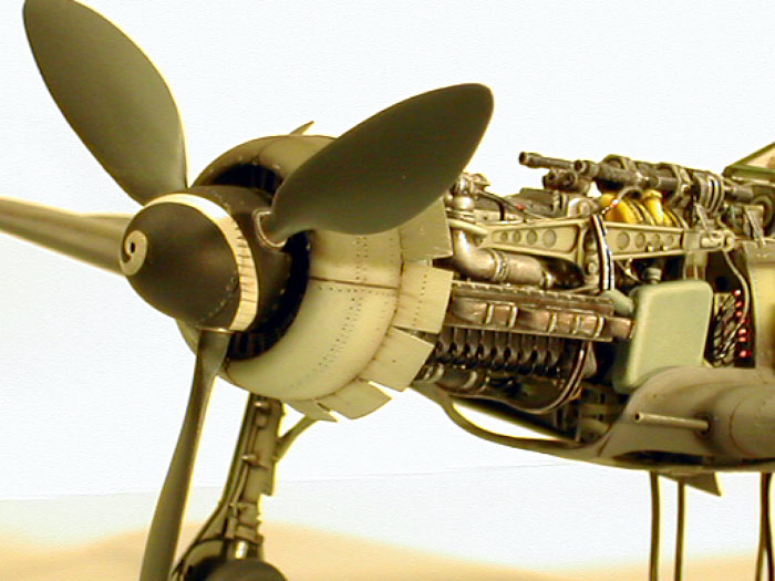
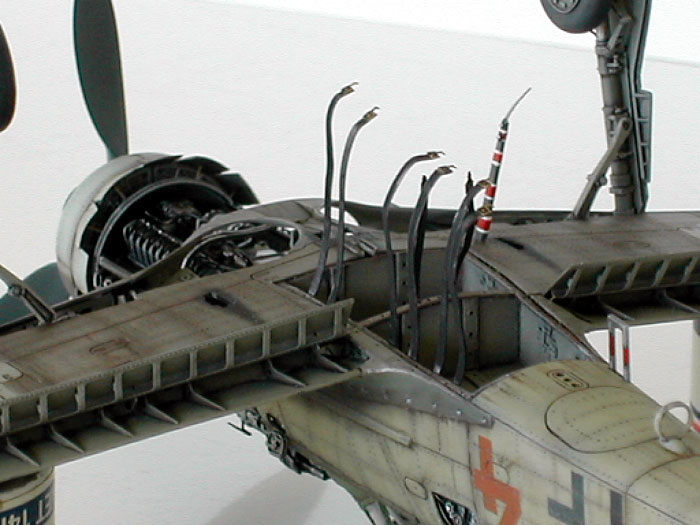
I am particularly pleased with the cowling support rails I built from
scratch. Also, the supporting arms of the engines seem too thin compared
to reference pictures. I used aluminum tubes instead. I think they have to
pretty thick and sturdy to support the weight of the engine. Other than
that, the FM details’ engine and detail parts are just fantastic, well
worth the price.
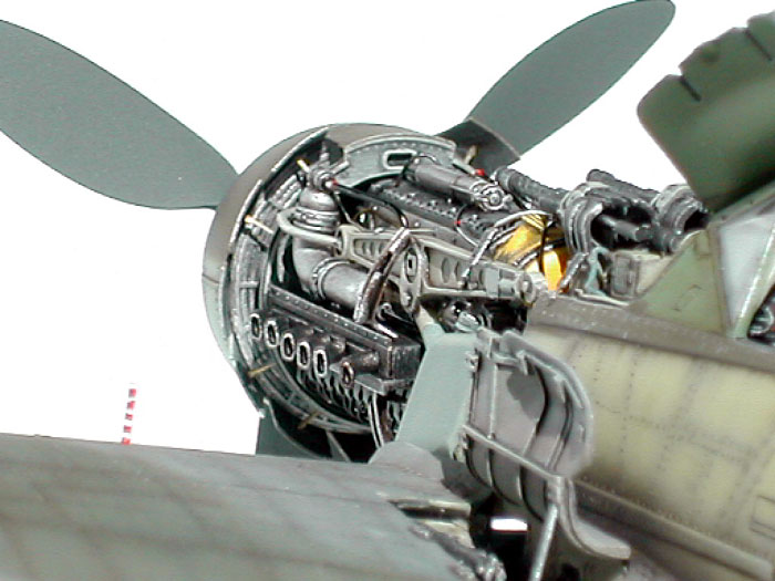
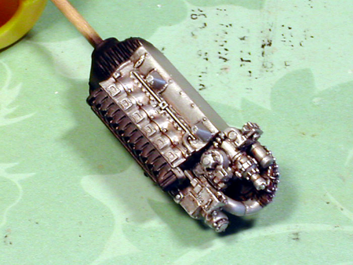
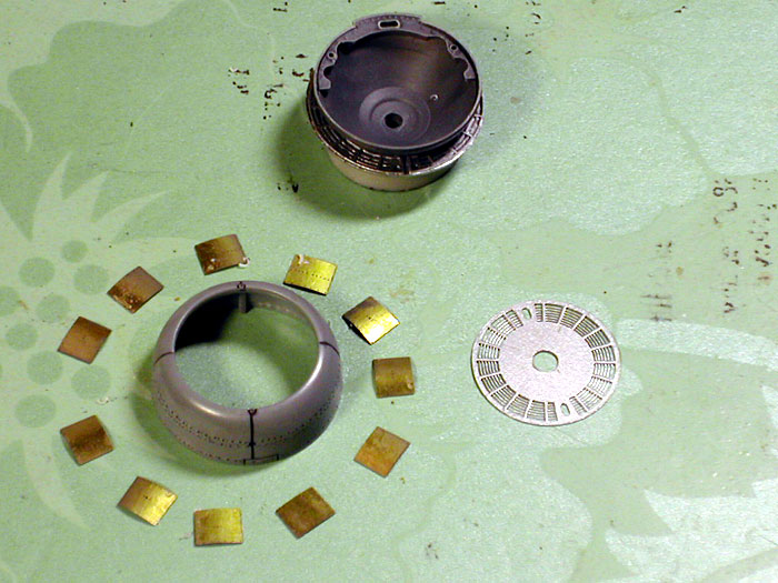
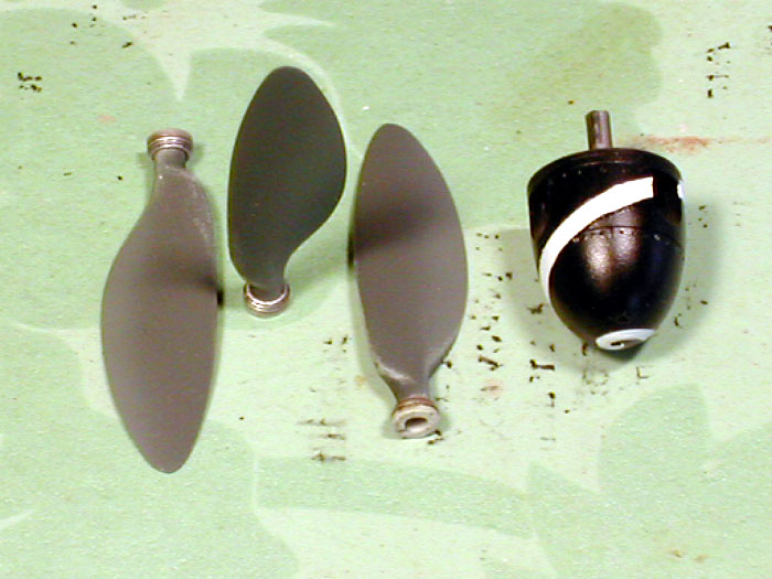
The radiator cowl ring received some extra detailing too. I added small
tube-shaped openings at 6 and 12 o’clock. Also drilled out a small hole at
the bottom panel line. Lastly, I also added rivet marks around the cowl
ring. I might have overdone the rivet marks, the painting made them subtle
enough. (cowlingparts02.jpg, radiator-cowling-prewashed01.jpg,
brown4_51.jpg, brown4_79.jpg around here) I used MDC’s beautiful spinner
and propellers instead of the parts that came with the kit.
Click the thumbnails below to view larger
images:
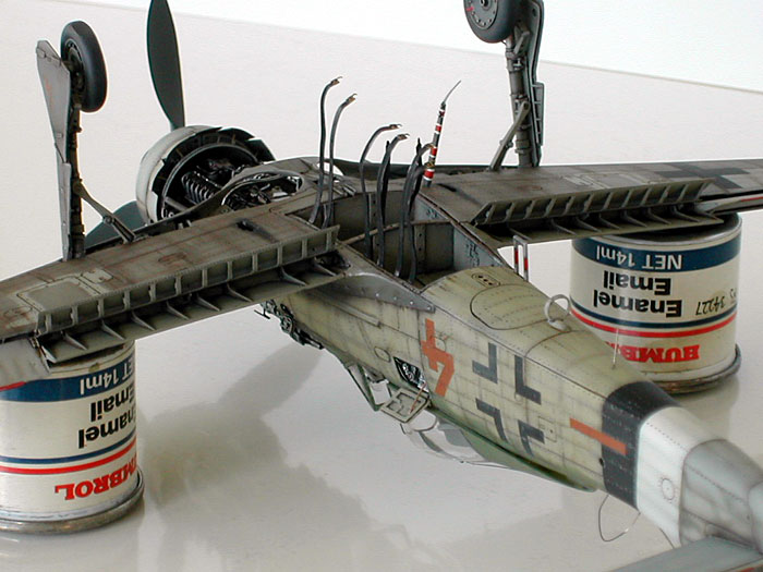
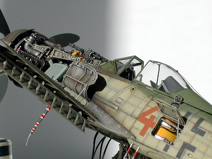
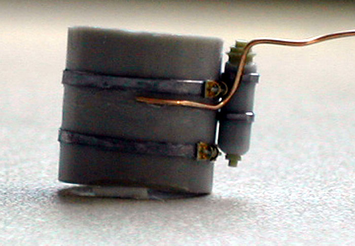
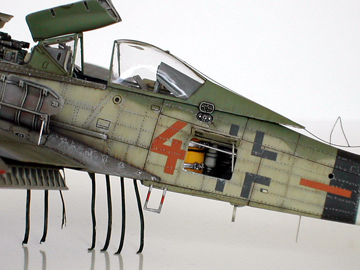
The radio comes from Aires’ Luftwaffe radio set. All the small hatches
were scratch-built. The center auxiliary fuel tank is also scratch-built.
I could’ve used the Verlinden update part, but I didn’t like the detail
and look of it. I also added fastening clips to the harness of the tank. I
then scratch-built the starter crank and placed it next to the auxiliary
tank. A lot of frames and wires were added to make sure the fuel tank had
the right background looks. Once they were painted and washed, I added the
enervator control cables. A couple of small fuel ‘caps’ were opened and
scratch-built.
Click the thumbnails below to view larger
images:
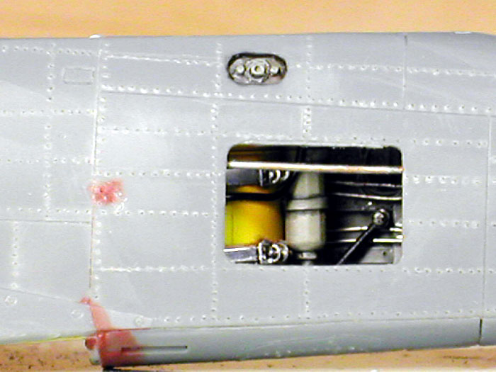
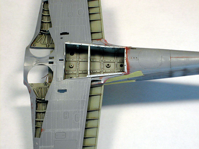
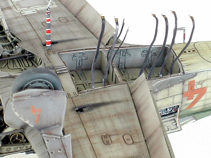
I found a nice drawing of the fuel tank compartment in the Mechanics of Bf
109 and Fw 190. I’ve always found simulating the mechanical looks of
airplanes challenging and satisfying. Naturally, I decided to open the
compartment and show the fuel tank harness. First, the compartment panels
were removed from the lower wing. I used my Dremel tool to thin the
surrounding areas to get the right scale thickness. Frankly, it was a very
tedious process that I intend not to repeat in the foreseeable future…
Then it was just cutting the right plastic panels, drilling holes, and
putting them together. Once painted and weathered, it was inserted into
the fuselage.
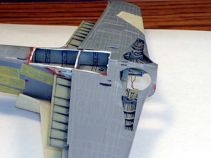
Fitting the compartment to the frame was particularly challenging for a
couple of reasons. First, the floor of the cockpit was a bit too thick
which made the compartment protrude too much. Time to summon my trusty
dremel… Second, both fuselages had to be thinned substantially since I
failed to calculate for the thickness of the kit parts. This is where I
should’ve compromised accuracy a little for a better fit. Once again, time
to summon my trusty dremel.. There was also an unforeseen problem as well.
Now that the fuselage parts had been thinned to the extent for them to
look translucent, I punctured through them several times while I was
embossing rivet marks around the cockpit. Time to summon putty and sand
paper… Of course, the wing didn’t fit well with the compartment despite my
‘sincerest’
efforts to calculate everything in 1/10 millimeter. Time to summon my
trusty dremel, putty and sand paper.
The result is very satisfying, but
only in retrospect.
Click the thumbnails below to view larger
images:
End of Part One
Go to Part
Two - landing gear, cockpit, painting, markings and weathering
Go to Part Three - Gallery of
Additional Images
Focke-Wulf 190
Modelling Manuals 20 |
|
|
|
|
US Price: $17.95
UK Price: £12.99
Publisher:
Osprey Publishing
Publish Date: May 25, 2002
Details: 64 pages; ISBN: 1841762687
|
|
|
Model, Images and Text
Copyright © 2004 by
Doowan Lee
Page Created 23 February, 2004
Last Updated
17 March, 2004
Back to
HyperScale Main Page |
 Home |
What's New |
Features |
Gallery |
Reviews |
Reference |
Forum |
Search
Home |
What's New |
Features |
Gallery |
Reviews |
Reference |
Forum |
Search