|
Tamiya's 1/48
scale
P-51C Mustang
Part One - Construction
by
Tony Bell
|
 |
|
North American P-51C
Mustang |

Tamiya's
1/48 scale P-51B/C Mustang is available online from
Squadron.com
In an effort to improve the performance at altitude of the Mustang, the
RAF authorized Rolls Royce to modify three Mustang Mk. I airframes to
fit them with the twin-stage supercharged Merlin 65 engine in late
summer of 1942. Although the Merlin 65 was optimized for lower
altitudes, it still maintained much better performance than the Allison
V-1710 at high altitudes. The Rolls Royce tests were highly successful,
prompting them to propose a program to refit 500 RAF Mustang Mk. Is with
Merlin 65s. However British wartime production capacity was already
stretched to the maximum and there were no resources available to carry
out the proposal.
Meanwhile in the USA, North American Aviation engineers were thinking
along the same lines. They fitted two Mustang Mk. Is with Merlin 65s and
were rewarded with similarly promising performance results. Even before
the first flight of a Merlin powered Mustang, the USAAF had ordered 400
of them.
NAA’s Inglewood, California factory was to be expanded to manufacture
the P-51B, but there was still not enough capacity to satisfy the
demands of both the USAAF and RAF. NAA opened another plant in Dallas,
Texas which was to manufacture P-51Cs. The P-51B and P-51C were
essentially identical, with the only distinguishing feature being the
serial numbers. The engines were supplied by the Packard Company, which
had reached an agreement with Rolls Royce to license produce the Merlin
under the American designation V-1650.
The NAA P-51B/C represented a quantum leap in high altitude performance
and range, allowing them to escort the heavy bombers all the way to
their targets deep into enemy territory. Whether or not it was the
“best” inline engine fighter of the war (a popular chat-room debate),
there can be no denying that the P-51B/C and later D models had an
enormous strategic impact on the WWII.
Aftermarket Accessories
I had originally intended to build my P-51B straight out of the box.
Hahahaha! Who was I fooling?
Upon digging the kit out of the stash/pile I discovered that I had
tucked the True Details resin cockpit set away in there.
(Thinks) Cool! OK, let’s use it - be a waste not to. Oops, the seat is
wrong! Looks more like a ‘D seat so I’d better get the Ultracast one. I
may as well get their exhausts, prop, spinner and wheels while I’m
placing the order. And ya know, I’ve never liked the TD instrument
panels. Why not grab the Eduard colour “Zoom” set, since I’ve been
wanting to see how they look anyway? Gosh, the cockpit is going to look
nice. I can’t leave the wheel wells alone, what with the inaccurate rear
wall. It wouldn’t be consistent with the cockpit! Hmmm, how ‘bout that
Aires wheel well?
And so it goes.
The following is a comprehensive list of the aftermarket stuff I used on
this model:
-
True Details: 48465 P-51B/C Cockpi
-
Eduard: FE219 Color-etch Zoom Cockpi
-
Ultracast: 48132 Diamond tread wheel
-
48133 Block tread wheels
-
48009 exhaust
-
48136 Spinner
-
48015 Seat
-
Aires: 4186 P-51B/C Wheel Well
-
Aeromaster: 48-211 Fighting Mustangs P-51B Part 1
-
Hobbydecal: st48002v1 P-51 Stencils
-
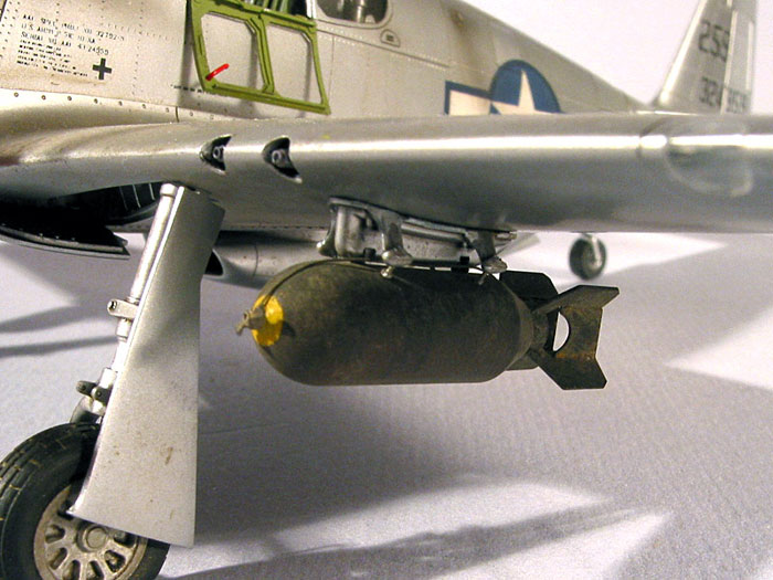
Verlinden: 1407 P-51 Mustang Underwing Stores
I don’t know if I spent more on the bells & whistles than I did on the
kit itself and I don’t want to know, frankly. More to the point, I
don’t want my wife to know!
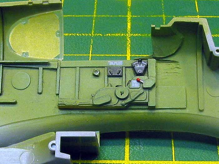
The Cockpit
The True Details cockpit is, as is typical of their stuff, very nice.
Installation required some minor surgery to remove the kit details and
thin the side walls down to get the resin bits to fit. This was
accomplished with my trusty Dremel tool and the resin side walls were
attached with five minute epoxy.
 The entire cockpit was airbrushed with Polly Scale U.S. Interior Green
(IG), followed by a sprayed coat of Future, a black enamel wash, a
sprayed coat of Polly Scale flat and finally a light drybrushing of
Aeromaster enamel IG lightened with white and yellow oil paints. The
details were picked out in Citadel acrylics with a fine brush using
“Chaos Black”, “Blood Red”, and “Chainmail” (silver). These acrylics are
ideal for painting small details. They cover well, dry nice and thin and
have a good working time. They also have amusing colour names like
“Rotting Flesh”, “Snot Green” and “Bad Moon Yellow” – a fun change from
boring old FS or RLM numbers. The entire cockpit was airbrushed with Polly Scale U.S. Interior Green
(IG), followed by a sprayed coat of Future, a black enamel wash, a
sprayed coat of Polly Scale flat and finally a light drybrushing of
Aeromaster enamel IG lightened with white and yellow oil paints. The
details were picked out in Citadel acrylics with a fine brush using
“Chaos Black”, “Blood Red”, and “Chainmail” (silver). These acrylics are
ideal for painting small details. They cover well, dry nice and thin and
have a good working time. They also have amusing colour names like
“Rotting Flesh”, “Snot Green” and “Bad Moon Yellow” – a fun change from
boring old FS or RLM numbers.
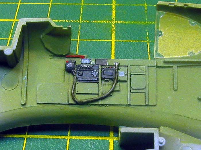
I used a few Reheat 1/72 data placards to add a bit of visual interest
and sourced some instruments from the decal heap which were punched out
and added to the floor to represent the fuel gauges.
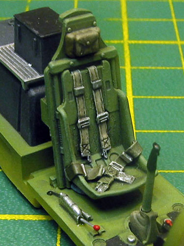
I replaced the incorrect TD seat with the more accurate one from
Ultracast. The seat was painted overall IG followed by XF-60 Buff for
the shoulder harness and Aeromaster faded OD 41 for the lap belts. The
belts were then given a wash of burnt umber oil paint, followed by a
light drybrushing with white. Finally the buckles were picked out with
“Mithril Silver”. The stitching was drawn on with an ultra-sharp pencil
and then brushed with Polly Scale flat.
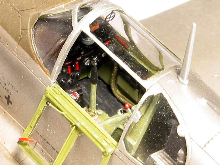
The instrument panel from the Eduard colour “Zoom” set looks nice and
busy, albeit a bit two-dimensional. Although the set also provides the
usual acetate instruments, I elected to use the instruments printed on
the brass part. To make the instruments suitably glossy several brushed
coats of Future were brushed on, which was also used to attach them to
the back of the panel. A spare set of rudder pedals (complete with NAA
logo) from the Eduard B-25B set were used in lieu of the TD resin ones.
They’re totally invisible, of course.
The TD gun sight was painted “Chaos Black” with Testor’s “Leather” for
the crash pad. Clear 0.010” styrene was used to make the objective lens
and reflector. The edges of the reflector were painted Gunze clear green
and it was attached to the sight with Future. I drilled a small hole in
the canopy bow and used white glue to attach a Tally-Ho photoetch ring
sight.
Click
the thumbnails below to view larger images:
Wings and Wheel Wells
Like every other known kit of the P-51 (perhaps with the exception of
the Rutman resin P-51B in 1/32), the Tamiya kit has inaccurate wheel
wells insofar as the rear wall is concerned. The kit depicts the rear
wall as being flush with the aft edge of the opening, whereas it reality
it was open all the way back to the main spar. I could have done some
real modelling and used sheet plastic to scratch build the well to the
proper dimensions, but it would be easier to simply purchase the Aires
well and glue it in, right? Right…
I had heard that, in general, the fit of Aires stuff isn’t the greatest.
But this was a relatively new release and, thought I, how bad could it
be? (Cue ominous music…) With uncharacteristic foresight, I figured that
is would be easier to attach the landing gear to the original plastic
mounting points than to the resin ones. I removed the pour stub and
lopped off the ends of the Aires part, removed the appropriate kit
details and dry fit the three wing pieces and the wheel well. The resin
fit very nicely indeed up against the lower wing, however when I tried
to fit the top wing piece I was confronted with a 1/8” gap at the
leading edge! How in the name of Sheperd Paine was I going to remove
1/8” of material?
Out came the 120 grit to take down the roof of the resin piece. Sand and
fit, sand and fit. The resin was translucent and had actually worn
through in places and there was still a considerable gap.
Out came the Dremel tool to thin the upper wing halves. Grind and fit,
grind and fit. I spent the next hour or so in a swirling styrene
snowstorm, merrily grinding away until daylight could easily be
perceived through the plastic. Finally, when there was no more styrene
or resin that could be safely removed, the wings just barely fit
together without compromising either the dihedral or the fit to the
fuselage.
After thoroughly washing the wheel well to remove all the resin dust, I
sprayed it with Alcald II Duraluminum, brush painted the rear spar zinc
chromate and applied a wash that consisted of a mixture of Polly Scale
flat and black ink. At this point I must say that in spite of the
difficult fit of the Aires part, the detail is outstanding and looks
great with minimal painting effort.
After attaching the wheel well to the lower wing with super glue, I
slathered five minute epoxy all over the top of the wheel well and
attached the upper and lower wings with superglue. The resultant
assembly was surprisingly solid, the epoxy glue returning some of the
lost strength to the thinned kit parts.
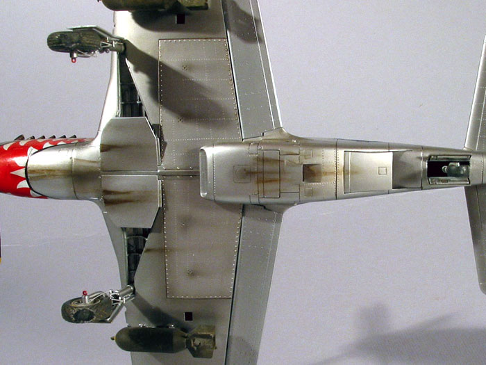
Having taken the leap of faith by risking butchering the kit’s wings, I
decided to go one step further and fill in the wing panel lines. In
order to take maximum advantage of the low drag laminar flow airfoil,
North American Aviation puttied, sanded, primed and painted the wings of
the P-51. In the interest of historical accuracy I decided I would do
the same on mine.
Now, I’ve been spoiling myself with lots of Tamiya and Hasegawa kits
lately, and my skill with fillers beyond Mr. Surfacer and minute amounts
of superglue has atrophied somewhat, to be honest. I broke out the
Squadron Green putty and filled in the panel lines (‘cept the gun bay
access panels and wing tips) on one wing, using masking tape to keep the
putty confined to the areas around the panel lines. After the putty
dried for a couple of days I sanded the surface with 800, 1000 and 1500
grit wet sand paper. I then primed the wing with Mr. Surfacer 1000
thinned with lacquer thinner and shot through my airbrush. Gad but the
wing looked awful. The porous filler stood out like a sore thumb, so I
sprayed heavier coats of Mr. Surfacer along all the panel lines and once
dry, sanded with 1500 and 3000 grit papers, ending up with a nice,
smooth surface.
For the remaining three wing surfaces I used superglue to fill the panel
lines. Working with a drop of glue on a piece of scrap plastic, I
repeatedly dipped the tip of my X-acto in the glue and ran it along each
panel line. This deposited just the right amount glue into the lines
while minimizing the overspill onto the surrounding plastic. Within 5
minutes of the glue drying I sanded again with 800, 1000 and 1500 grit
papers and primed (after a good scrubbing with dish soap) with Mr.
Surfacer 1000. A few touch ups followed by a final rubbing down with the
3000 grit and I set the wings aside to concentrate on the fuselage.
Fuselage
Before joining the fuselage halves, I Dremelled the plastic behind the
perforated cooling vents on the lower nose cowling to open up the holes.
The vents were backed with scraps of styrene painted black to prevent a
see through effect. I also inserted a piece of brass mesh, painted
black, behind the carburettor opening under the spinner. Not exactly
accurate, but it’s better than a gaping hole. As a further precaution, I
painted everything visible through the carburettor opening flat black.
After painting the radiator bits silver (Alclad again) I joined the
fuselage halves together. I used superglue for this, as liquid glue
continues to shrink for several weeks and can leave a ghost seam that is
very noticeable under a natural metal finish.
I sanded and polished all the seams smooth, being extra careful not to
introduce flat spots that would again be visible under NMF. The lost
detail on the underside of the belly scoop was rescribed with a
Verlinden template and a sewing needle in a pin vise. After scribing I
brushed a small amount of liquid cement into the scribed lines and let
it dry before sanding. This prevents the raised ridges from being pushed
back into the groove and makes it easier to clean out the sanding dust.
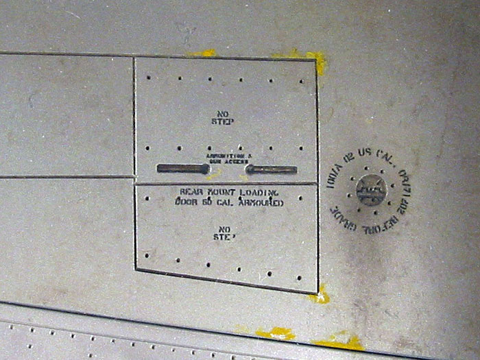
On the lower access panels, the lost Dsuz fasteners were recreated with
a Jeweller’s beading tool.
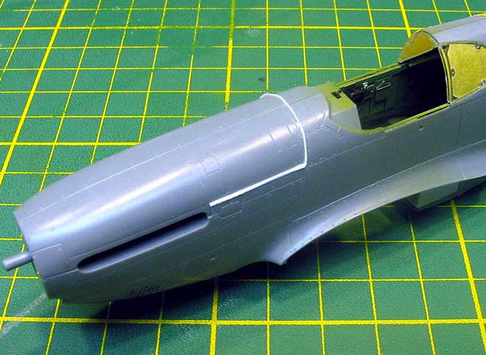
A test fit of the upper engine cowling piece revealed that there was a
gap of about 0.007” at the rear and bottom. This was a bit of a surprise
to me considering the almost legendary fit of this kit. I’ve never heard
of this before and can only assume that it was of my own doing. In any
case, I elected to shim the parts with sheet styrene and sand them to
fit.
I wanted to pose the canopy open so as to show off all the aftermarket
cockpit stuff (what’s the point otherwise?), but I didn’t want to spoil
the nice lines of the Mustang by having the top portion of the canopy
open. Shamelessly stealing the idea from fellow IPMS Toronto member and
modeller extraordinaire Rob Bilinski, I took the closed canopy and
carefully cut the side hatch away, leaving the top closed. I removed the
rather clunky attachment ridge from the side hatch and detailed it with
strip styrene and wire whereupon I masked it and painted it IG and
Alcald Aluminum and set it aside for final assembly.
After masking and attaching the canopy parts, the fuselage was carefully
sanded smooth with 1500 grit wet & dry sandpaper and plenty of water,
followed by an airbrushed primer coat of Mr. Surfacer 1000 thinned with
lacquer thinner. The first coat of primer revealed a hairline crack on
the upper spine of the fuselage. I applied a few drops of thin super
glue to the inside of the fuselage by dropping it down through the tail
wheel opening and letting it run down the spine. A heavy coat of Mr
Surfacer was sprayed on the spine to fill in the crack. Once the Mr.
Surfacer had dried I rubbed it down with 1500, 2000 and 3600 grit
polishing cloths, again with lots of water.
Looking through my myriad of Mustang material I noticed that a good
proportion of photographs of aircraft of the ground showed a slight
droop to the elevator. This is due to the fact that for ground
manoeuvring the tail wheel was unlocked by pushing the control column
forward. Because of the notch for the mass balance, simply cutting the
elevators off and repositioning them was not going to be easy. Instead,
I took the kit parts and, using RTV rubber and two part resin, took a
cast and made copies of the elevators. I then cut away the plastic
elevators and cut and trimmed the resin duplicates to fit.
At this point I elected to leave the wings and stabilisers separate in
order to facilitate riveting and painting. The fit of these parts is so
good that they can be attached after painting without the need for any
filler.
Rivet, Rivet, Rivet
Those of you who have read my Tamiya P-47D
Bubbletop build feature here on Hyperscale
http://hsfeatures.com/p47dbubtb_1.htm can skip this
section, as it is largely the same information repeated.
In order to reproduce the rivets I made the pounce wheel from a piece of
1/16" brass rod, with a steel sewing pin for the axle and a watch cog
with a diameter of approximately 1/8" and a tooth pitch of about 0.75mm.
I drilled a hole in the brass rod for the sewing pin axle and then cut a
slot lengthwise into the rod perpendicular to the axle hole. I annealed
the sewing pin and mounted the cog in the brass rod with the pin and cut
it almost flush with the rod. I then mushroomed the ends of the pin by
tapping the axle with a hammer.
To guide my home-made pounce wheel, I laid a piece of electrical tape
over top a piece of Tamiya masking tape and cut a 4” by 3/16” strip. The
electrical tape provides the thickness and flexibility to guide the
pounce wheel, while the mild adhesive of the Tamiya tape allows it to be
applied and removed over and over again without leaving any sticky
residue.
For reference, I used drawings from the back of an Osprey book, and of
course plenty of photographs. I applied rivets to the fuselage, tail and
fuel tank on the underside of the wing, leaving the wings alone since
they are supposed to be smooth. The wings and stabilizers had not been
attached to the fuselage at this point, making it easier to get at their
respective root areas with the pounce wheel.
I worked in sections, first outlining each panel and then filling it in,
constantly referring back to the plans. For each rivet line, I
positioned the tape guide and ran the wheel along at about 2-3 r.p.s.
(rivets per second), being careful to reduce the pressure as I crossed
any panel lines. Any slip ups were fixed with Mr. Surfacer 1000 and 1500
grit sandpaper.
Once finished, I took some well worn 2000 grit wet & dry sandpaper and
soapy water and rubbed the entire model down in order to make the rivets
a little less prominent.
The results look a lot more impressive than the actual skill to produce
them, requiring more patience than anything else. The most challenging
aspect is fabricating the pounce wheel, and with commercial products
such as “Rosie the Riveter” available (
http://riveter.wz.cz/Riveter.pdf )
this should no longer be an issue.
Click here to visit Part
Two
Click
the thumbnails below to view larger images:
P-51 Mustang
From the RAF to the Mighty Eighth
Special Editions (Aviation) 1 |
|
|
|
|
Author: Michael O'Leary
US Price: $10.95
UK Price: £6.99
Publisher:
Osprey Publishing
Publish Date:
September 15, 1997
Details: 128 pages; ISBN: 1855327147 |
|
|
Model, Images and Text Copyright ©
2005 by Tony Bell
Page Created 06 May, 2005
Last Updated
09 May, 2005
Back to
HyperScale Main Page |
 Home
| What's New |
Features |
Gallery |
Reviews |
Reference |
Forum |
Search
Home
| What's New |
Features |
Gallery |
Reviews |
Reference |
Forum |
Search